By: Ameen Alattas
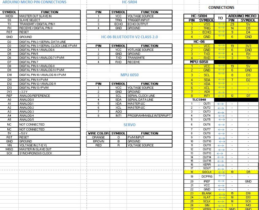
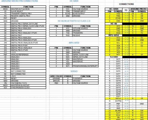
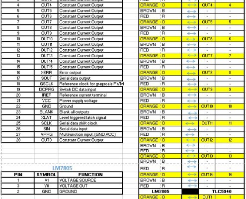
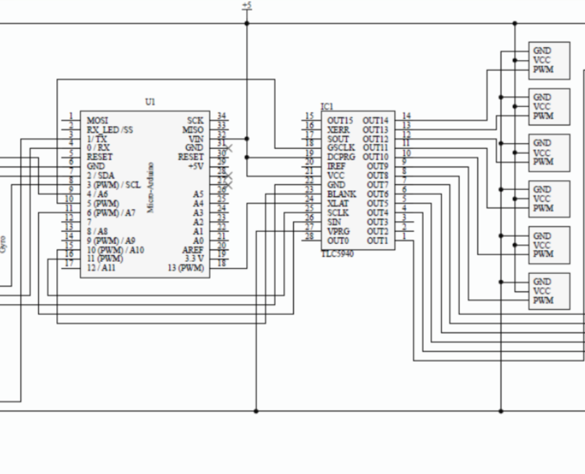
The above pictures show how the the parts should connect in the final project.
Picture 1 shows the pins of each component, their numbered position, their labels, and their functions.
Picture 2 shows how the components interact with each other.
Picture 3 shows a visual interaction the components have with each other, however its purpose is primarily for modeling the PCB board.
U stands for components like gyros, microcontrollers, or ultrasonic sensors.
IC stands for integrated circuit chips.
J stands for components like resistors, fuses, etc.


