IR shield Fabrication and Test
IR shield Fabrication and Test
Written by Charles Banuelos(Division Manager Design and Manufacturing) & Muhannad Al Mohamed(Division Manager E&C)
Approved by Charles Banuelos(Division Manager Design and Manufacturing), Muhannad Al Mohamed(Division Manager E&C), Mark Huffman(Project Manager Goliath), Zach Oyog (E&C Sojourner)
Fabrication
Fabrication of the 3DoT IR shield occurred on 12/5/2017 due to the fact that Color Sensor Shield fabrication was not able to be completed. There was no stencil available to use to solder the IR shield; therefore, hand soldering is needed. The IR sensors themselves where placed flushed to the board to ensure that the IR sensors do not come contact the ground during the mission.
The fabrication process did have some setbacks while soldering parts. The first major set back was placing the surface mount parts on top of the IR shield without using the pick and place machine. The lack of the pick and place machine caused many dead joints at surface mount parts due to improper placement. The other setback was the actual look of the solder themselves and many needed to be redone due to none uniformity.
Test
Testing the IR shield was done by applying an Arduino code to it. Since the IR shield uses the six pins of the front header of the 3DoT board (A2,A3,SDA,SCL,3.3V VCC,GND), the code optimizes direct reading from the pins using Arduino’s built in read function. The used code was applied to a 3Dot board to ensure a proper running of the sensors. The test revealed that we were successful on fabricating four shields out of five. The fifth IR shield will be taken back to fab to ensure that all are working.

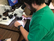
Placing components during Fabrication of the IR sensor shield
Update 12/7/2017
The following code is used to test the distance measurement for each IR ICon the 3DoT IR shield.
Update: 12/15/2017
The following code was altered by changing the reading commands from “analogRead” to “digitalRead.” The reason for this change was because the SDA and SCL pins are not actually analog pins, thus, the function “analogRead” would not return actual measurements. Therefore, the command “digitalRead” was used instead to get binary inputs as an indication that the pins are actually working.
Code :
////////////////////////////////////////////////////////////////
//  Name     : 400D IR Shield Testing Code                    //
//  Author   : Muhannad Al Mohamed                            //
//  Date     : 5 December, 2017                               //
////////////////////////////////////////////////////////////////

 //defining variables to save measurements
 int farRight_IR;
 int innerRight_IR;
 int innerLeft_IR;
 int farLeft_IR;

 void setup()
 {

   Serial.begin(9600);

   pinMode(A3,INPUT);      //Top view, pins up, far right IR sensor
   pinMode(SDA,INPUT);     //Top view, pins up, second right IR sensor
   pinMode(SCL,INPUT);     //Top view, pins up, second left IR sensor
   pinMode(A2,INPUT);      //Top view, pins up, far left IR sensor

 }

 void loop()
 {

  //reading values of IR sensing into variables
  farRight_IR = digitalRead(A3);
  innerRight_IR = digitalRead(SDA);
  innerLeft_IR = digitalRead(SCL);
  farLeft_IR = digitalRead(A2);

  //printing measurments in searial monitor
  Serial.print("farRight_IR =  ");
  Serial.print(farRight_IR);
  Serial.print("  ");
  Serial.print("innerRight_IR = ");
  Serial.print(innerRight_IR);
  Serial.print("  ");
  Serial.print("innerLeft_IR = ");
  Serial.print(innerLeft_IR);
  Serial.print("  ");
  Serial.print("farLeft_IR = ");
  Serial.println(farLeft_IR);


  delay(250);
 }