JLCPCB DRC and Ordering
By Jaap de Dood,
Table of Contents [hide]
Introduction
JLCPCB is a popular new source for ordering PCBs. Their advertised price for PCBs is extremely low, although, shipping costs are usually $20-30. Nonetheless, this usually still comes out cheaper than sources such as OSH Park, especially when ordering in bulk. Their build times are also very fast so the result is cheaper, faster PCBs of comparable quality. The only downside is that their website is not quite as user friendly, and occasionally outdated. Hence, I’m writing this article to show you how to export your design from EAGLE, to files that JLCPCB will accept and you will receive without any manufacturing errors.
Running a DRC with JLCPCB Settings
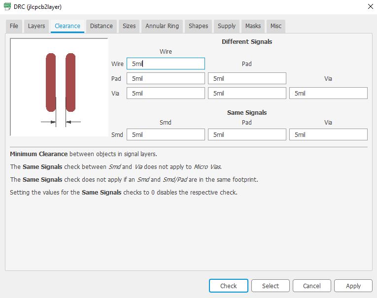
Different manufacturers have different capabilities, such as the minimum trace width or drill size. To make sure our design conforms to these standards, we must run the EAGLE Design Rule Check (DRC) to check our design.
With your board view open in EAGLE, click the “DRC” button.
A window should open where you can set the various parameters.
JLC has their capabilities listed on their website here: https://jlcpcb.com/capabilities/Capabilities
Luckily for you, you won’t have to enter all these manually, as I have made a file you can import to do this for you. Download the .dru file below.
https://drive.google.com/open?id=1_e-_1_OwLYHF4yCS4vo2QgWa3IrF-m5K
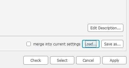
Next, click the “Load” button in the bottom right of the DRC window and navigate to the .dru file you just downloaded.
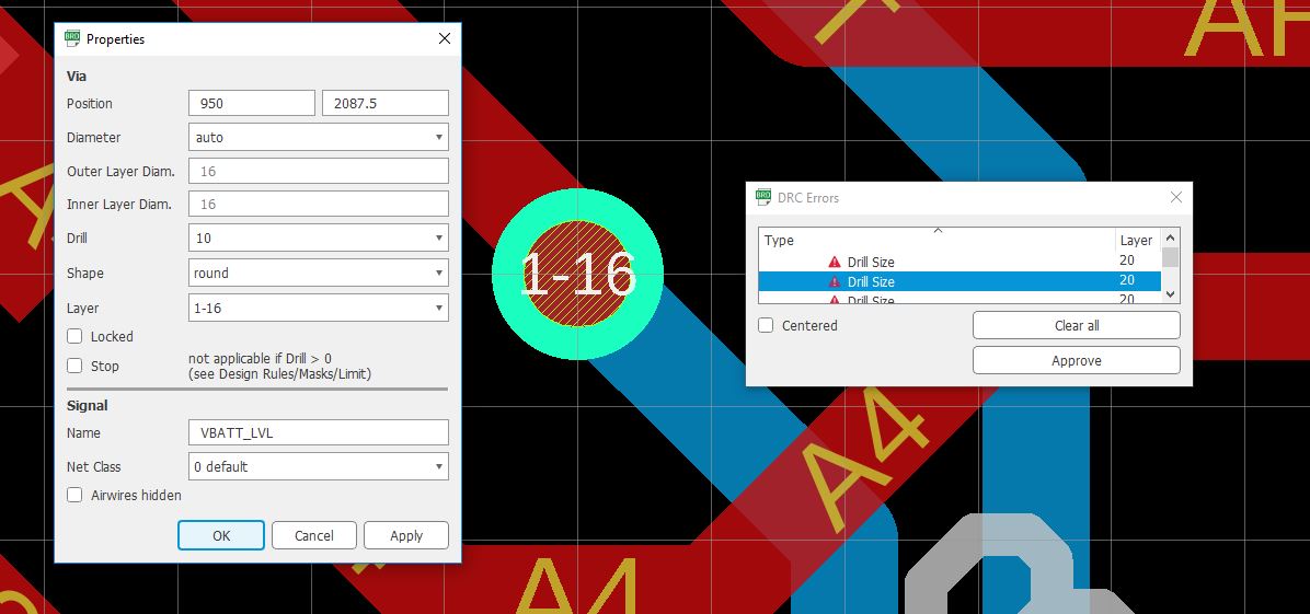
Next, hit “Check” and fix any errors you may have.
Here, for example, I am using a 10mil via. This is smaller than JLCPCB’s minimum via size of 0.3mm, which is about 12mil.
Generating the Gerber Files
Once you have fixed all your DRC errors and are confident the board is ready to be fabricated, it’s time to generate the gerber files. Gerber files are a set of different files, i.e. a drill file, silkscreen file, outline etc., that JLCPCB can load into their machines to fabricate your PCB.
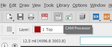
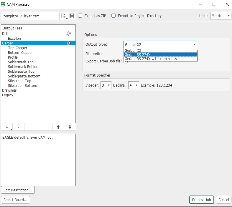
To get started, click the “CAM Processor” Icon in the top right corner of your EAGLE board view.
Next, navigate to the “Gerber” tab, and select “Gerber RS-274X” as the output type.
Check “Export as ZIP” at the top of this same window.
Finally, click “Process Job” and save the .zip file somewhere convenient.
Ordering your PCB
Finally! It’s time to order our PCB.
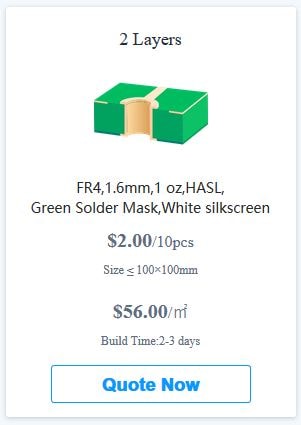
Open https://jlcpcb.com/ and click any of the “QUOTE NOW” buttons.
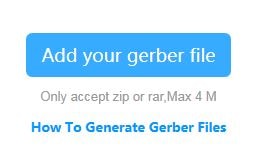
Click “Add your gerber file” and find the .zip we generated earlier.
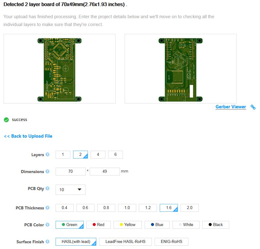
Wait for the preview to appear and confirm the dimensions have been automatically entered correctly.
It is important that the preview appears since, if there are issues with your gerber files, the preview will not appear and JLCPCB will accept them at first, but email you later if they can’t fabricate your PCB.
The dimensions should match so that you don’t pay more than you should.
Select the PCB quantity you want, and leave the rest of the settings alone unless you have specific requirements.
If you are going to be soldering your PCB using a reflow oven, now is also your chance to check “Order together with laser stencil” to automatically add a metal stencil to your order for $6.
References/Resources
- https://jlcpcb.com/capabilities/Capabilities
- https://support.jlcpcb.com/article/22-how-to-generate-the-gerber-files (Instructions for EAGLE outdated as of 11/19/18)

