Dragonbot/Spring/2021
LDC Room Configuration Software Breakdown
Author: Muath Almandhari
Table of Contents
Introduction
The fundamental objective of this project is to build an autonomous guided robot that will use three LDC sensors placed in the front of the chassis which will detect copper tape placed in the walls of the maze to solve it. Therefore, this blog post will go over the software programming algorithm used to navigate Dragonbot throughout the maze.
Program Breakdown
As a navigation design engineer, the main goal is to make Dragonbot go to every room and get its walls configurations and send it to the Game Software in order to solve the maze. Thus, here is a breakdown of the navigation programming code for every function used in the program.
Library and Addresses Initialization
At the beginning of the code, I started off with including the LDC1612 library and I2C communication library. Then, I defined the motor pins, as well as each LDC IC address. Finally, I defined the proper sensitivity LDC ranges for the right, left, and front sensor and the variables to store the results of the channels.
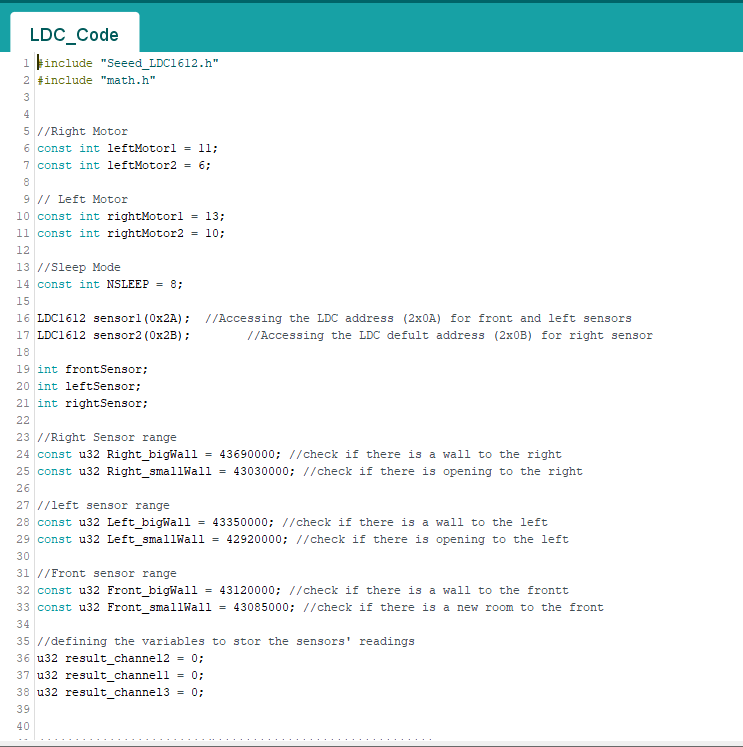
Image 1: LDC1612 and I2C library Initialization.
The Setup Function
At this function, I initially set the motors pins and initialized the I2C communication for the two LDC ICs. After that, I set the configurations of the LDC sensors. Because of the fact that I am using multiple channels in a single LDC IC, I used the multi-channel configuration set up for both of the sensors.
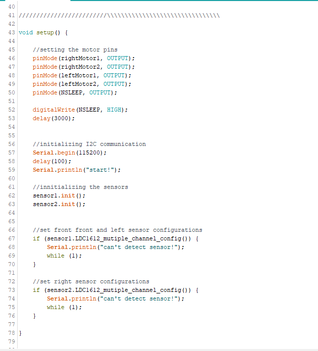
Image 2: void setup() Function.
LDC Sensors’ Functions
For this part, I had to create two separate functions in order to get the readings of the LDC sensors. Therefore, I started with the first LDC sensor function “LeftAndFront()” which holds the left, and front sides sensors. This function will return an array of 0 and 1 for the reading of the front and the left sensors respectively. Next, I created another function “rightOnly()” which will output the reading of the right sensor as a 0 or 1 also.
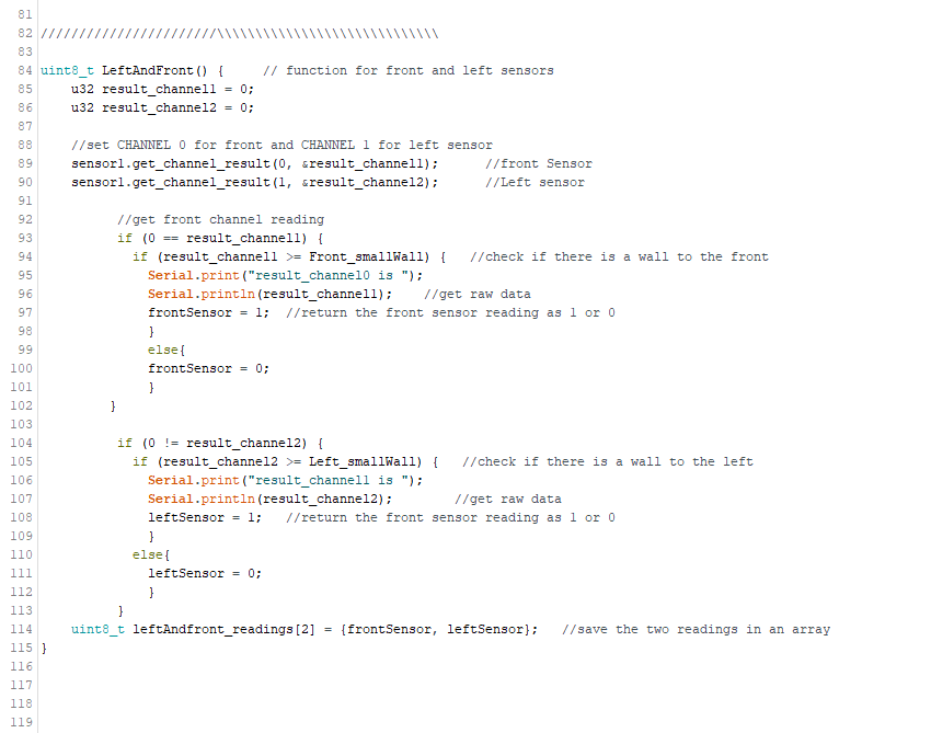
Image 3: Left and Front Sensors Function.
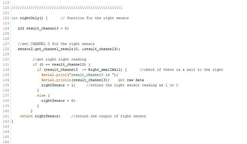
Image 4: Right Sensor Function.
Room Configurations Function
“NAVIGATION_allSensors()” is a function that would call both “LeftAndFront()” and “rightOnly()” functions and return a hexadecimal number output for the readings of all the sensors. This function will return the reading of the sensors for all the room configuration possibilities in the direction sequence of (right, front, left). This function is very important because the output of it will be sent to the game software to get the room configurations of every room.
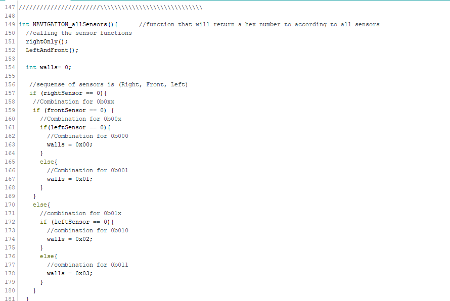
Image 5: Room Configuration Function.
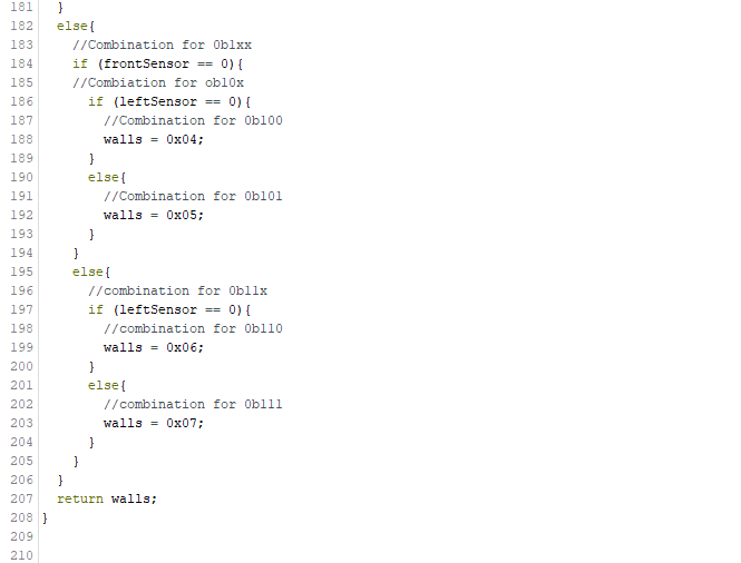
Image 6: Room Configuration Function Continue.
Walls Direction Function
“wallsDirection()” function will take the compass as input and call “NAVIGATION_allSensors()” in order to get the room configuration and the directions of the wall based on Dragonbot’s orientations at that moment. The image below shows one case when Dragonbot is facing north.
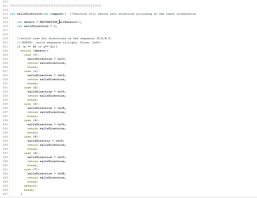
Image 7: Room Configurations With Respect to Dragonbot’s Orientation.
Program UML Diagram
This program can be divided into three main stages which are: getting the readings of the right, front, and left sensors, getting and the room configurations based on the sensors’ readings as a hexadecimal integer, and getting the room configurations based on the robot’s orientation at every room entered.
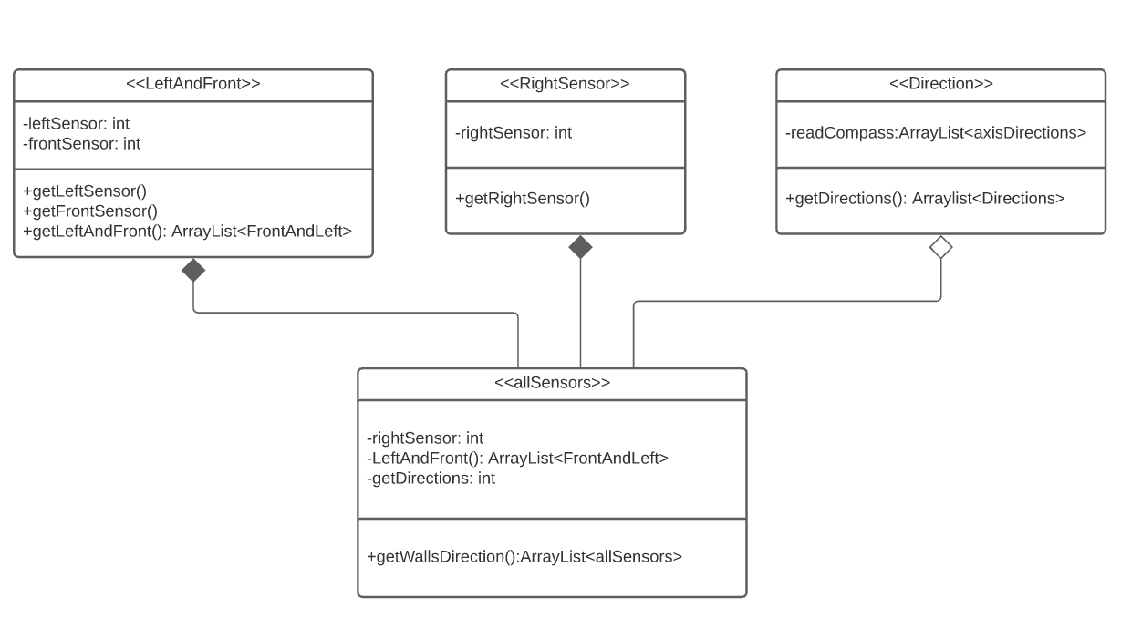
Image 8: Room Configuration Program UML Diagram.
Conclusion
In conclusion, this blog post is a breakdown of the program code that was used to get and send the room configurations to the game software. It starts with getting the sensors’ readings, then gets the room configurations based on the readings, and finally based on the robot’s orientations.