Level 2 Requirements
By Tuan Vo and Elaine Doan
Structural Subsystem Requirements
- The VTOL will use four 55 mm electric ducted fans per the request of the customer. The four fans gives enough thrust to lift themselves, the required electronics for control, and a body. The body is estimated to be 298g from the fan selection study by Juan Montana and will give control of 36.5% thrust control. Using a margin of 15% for the mass of the body, we conclude that the body of the aircraft, not including any electrical components, must weigh less than 343g.
- Weigh the body and ensure this does not exceed 343g.
- After mounting all hardware and body along with the four fans, run the fans at 63.5% thrust. The VTOL must achieve takeoff at this point.
Wireless Communication Requirements
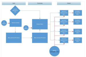
- To wirelessly control the VTOL from a minimum range of 40ft, the VTOL system will include the XBee wireless RF module (maximum range of 100m or 300 ft.). The transmitter of the XBee wireless RF module will be connected to the remote control. The receiver of the XBee wireless RF module will be connected to the Arduino.
- Perform communication testing of the XBees using X-CTU. Make sure the “Baud Rate” of both the transmitter and receiver match each other. (https://sites.google.com/site/xbeetutorial/xctu).
- Using the remote control, command the VTOL to move forward, backward, up, down and side to side. The range of communication must be at least 40ft.
Control System Requirements
- To achieve flight at the elevation of 8ft, four electronic speed controls will be used to increase and decrease the speed of each fan by 20% at a reference of 63.5% lift off thrust.
- Write a test code using the Arduino Nano to control the speed controllers and monitor it as it run at lift off thrust. Determine if the VTOL reaches desired height by comparing with an obstacle or measurement. The VTOL must stay at desired height with a deviation of 1/2 feet.
- Raise or lower the speed of each fans individually by +/- 20% thrust. Watch and confirm expected desirable increase or decrease in fan rpm. This increase and decrease determines the VTOL’s directional movement.
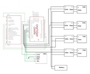
- To support flight around the ECS 317 room, the VTOL will use the inertial movement unit. The inertial movement unit includes an accelerometer and gyroscope that will prevent the VTOL from undesired tilting, drifting or flipping during the flight around the room. The inertial movement forms a closed loop control system that will stabilize the VTOL throughout its flight around the ECS 317 room.
- Create a test program using the Arduino that will monitor the amount of tilt and acceleration present as the IMU is moved.
- To achieve flight (vertical lift off), weight is a major concern; as a result, the microprocessor of the VTOL will be the Arduino Nano. The Nano weighs only 4 grams and at the same time its I/O ports are accessible to support four fans and receive inputs from both the user and the IMU.
- Specs of the Arduino can be verified at the link provided below: http://arduino.cc/en/Main/arduinoBoardNano#.UylKA_ldXGA
Power System Requirements
To provide enough power for the VTOL to fly around the ECS 317 class once (85.75 ft.), the main motor battery(s) must provide a minimum 1489 mAh to sustain required flight time. This will provide the speed controls and consequently the fans with enough power to provide 70% thrust for 2 minutes. The batteries chosen are two 1300mAh LiPo batteries. Two speed controllers and two fans will be connected to one battery.
- Verify at battery study and mAh ratings link: https://www.arxterra.com/motor-battery-selection/
- Before testing the batteries in actual flight, hook up the batteries to their specified fans. On full charge, have the batteries power the fans at 70% thrust and record time from full to empty, signified by when any of the fans start to reduce in rpm. Time recorded must be longer than two minutes minimum flight time.


