Limbi Generation #2 Fall 2019
Limbi: Androgynous Connectors
Author/s:
Alondra Vivas
Edward Villanueva
Colin Rogers
Table of Contents
The Importance of the Connectors
The androgynous connectors are a crucial step into Limbi’s success, and arguably the most important revision of JPL’s design that is needed. An androgynous design means that the connectors have both a male and female portion to them. JPL’s design is androgynous, however it requires constant electrical power to keep the connection locked, which poses the problem of unnecessary power usage. Therefore the solution to this problem comes from a mechanical design of the androgynous connectors, that would keep two connectors in place, without having to have a constant source of power. The androgynous connector must have a secure lock, that is also easy to lock, as well as unlock, requiring almost no outside force as these modules will be in space, where every force needs an equal opposing force so that it doesn’t drift off. The first generation Limbi team realized that this would be an issue as well, however their solution saw the usage of permanent magnets to allow for quick connection, but it lacked features to make it androgynous while the first generation Limbi used a different connection than the modules. The second generation Limbi hopes to improve on the first generation Limbi’s design of the connectors by making it androgynous and requiring a mechanical lock. Below are all the design ideas that second generation Limbi had up until the finalized connector was created.
Design Ideas
Headphone Jack with Velcro Design
The headphone jack idea was based off of the original LEGO description of the androgynous connector. The idea was to use mono audio jack connectors to snap the cubes together. This produced a simple design that could easily carry power between the cubic modules and it was relatively simple to model. We didn’t go with it because there was no way to control having a clear on and off state. The strength of the connection was also a concern. To add additional strength, the idea of using Velcro was also discussed but quickly dismissed because there would have to have been a strong opposing force to take the Velcro apart from the connector which in space makes this task even trickier than it is. This can be seen depicted in the image below with the “hook” and “loop” portions of the drawings. This was a very early idea so a rough estimate of its size was a 5X5 cube which we later realized was too large. Another issue that was brought up was the lack of clear interface with the second generation Limbi. A generic connector can be seen on the right side of the cube (the + shape), which would have been fleshed out eventually. It was designed by Colin Rogers.
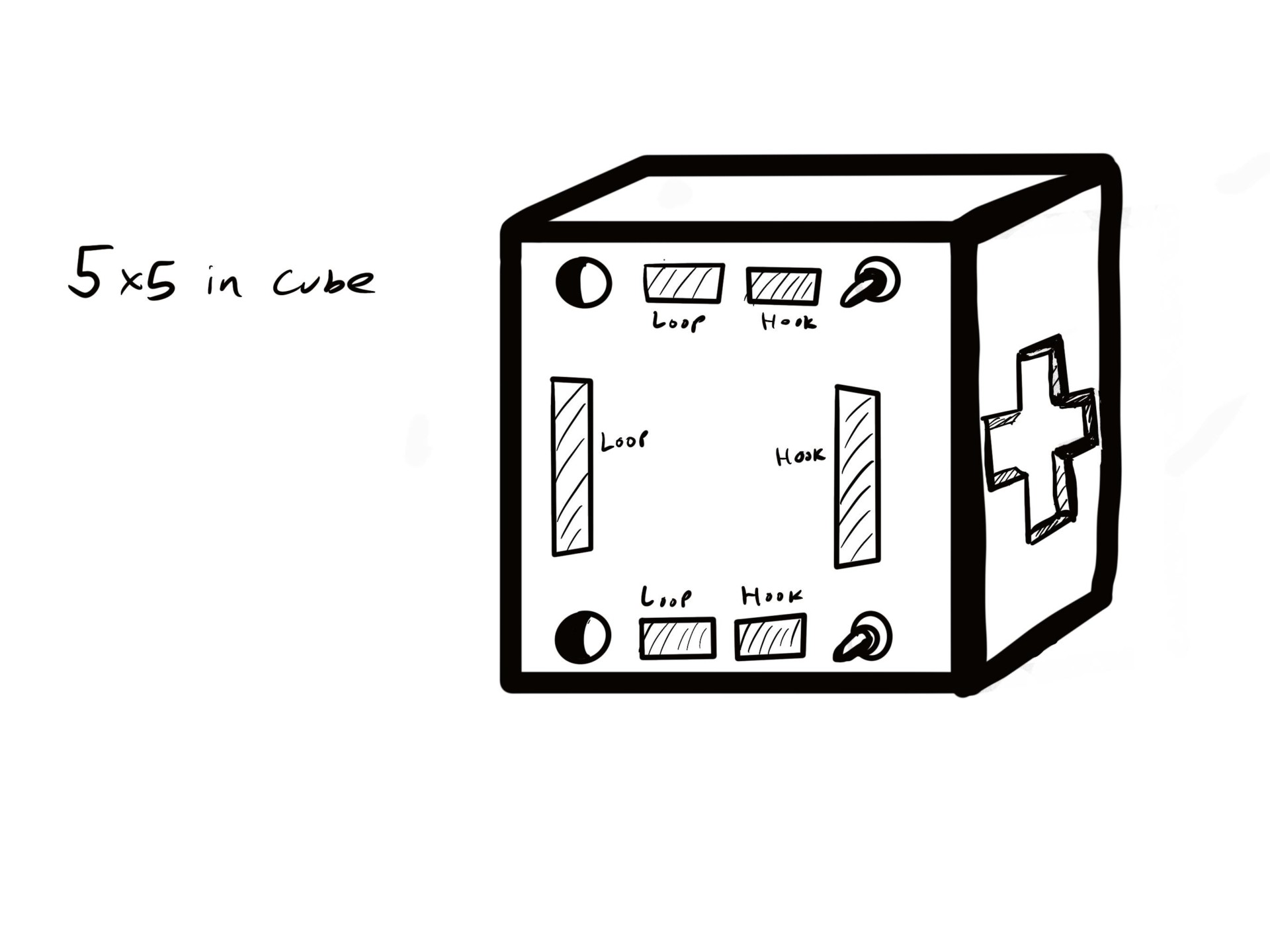
Figure 1. Module design with velcro and headphone jacks
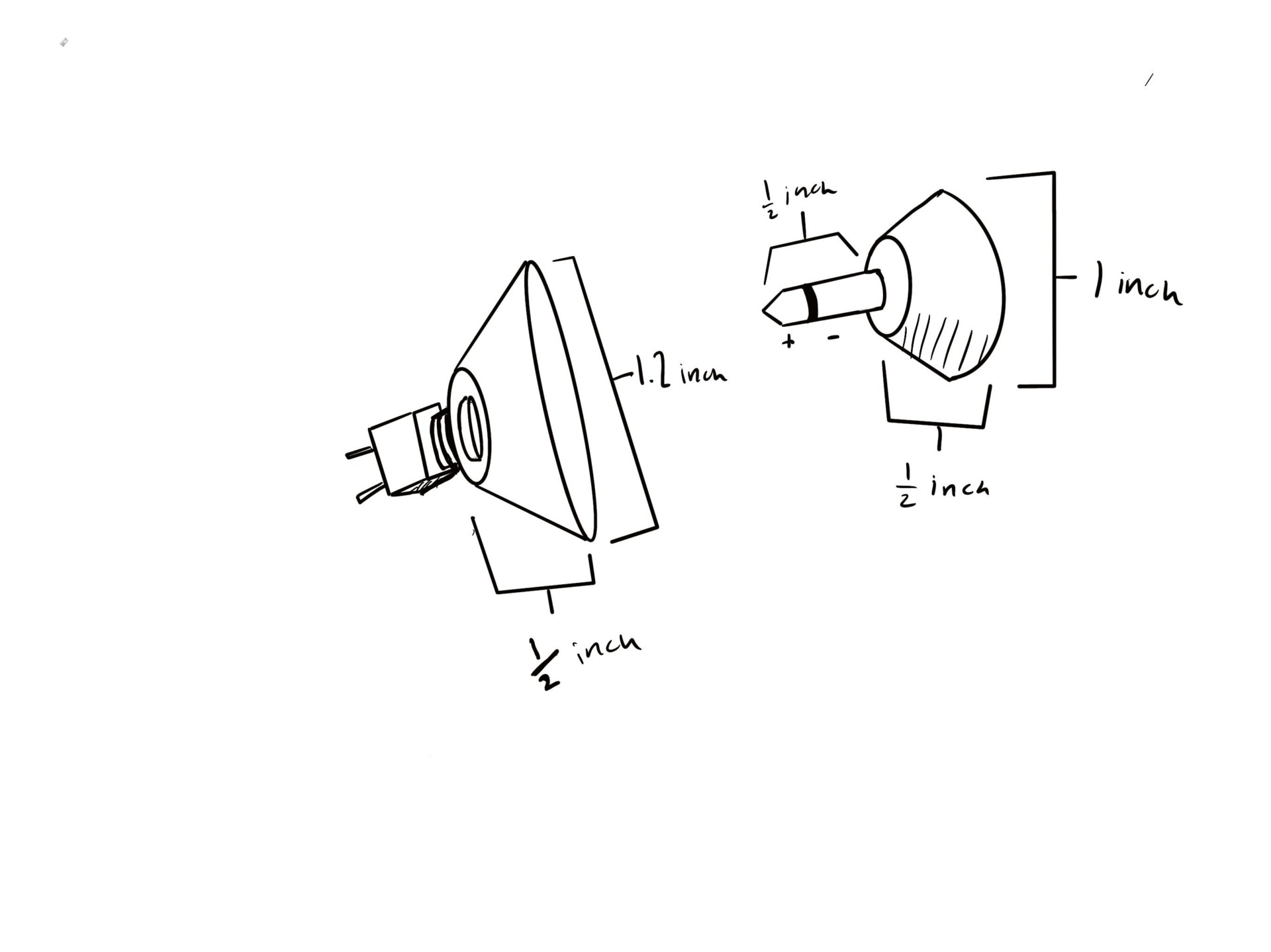
Figure 2. Close up of the headphone jacks
Screw Connector Design
This screw connector design came from the idea that screws create a tight mechanical seal and take apart. Making it androgynous would be possible by simply putting two screws horizontally of one another and two holes to place the screws in the alternate horizontal way. This design did not get approved because it would have required 2 motors per screw making the mass of the cubic module greater than necessary. We would have used 8 screws per cubic module making each cubic module have 8 motors as well. Also if something were to get stuck within the holes of the screws it would be difficult to clean it out in space. The below pictures are SolidWorks designs of this screw connector. The bottom picture shows the measurements of the holes and the screws. We went with these measurements because the original idea was that this would be a 5×5 cube but we later came to realize that was too large. It was designed by Alondra Vivas.
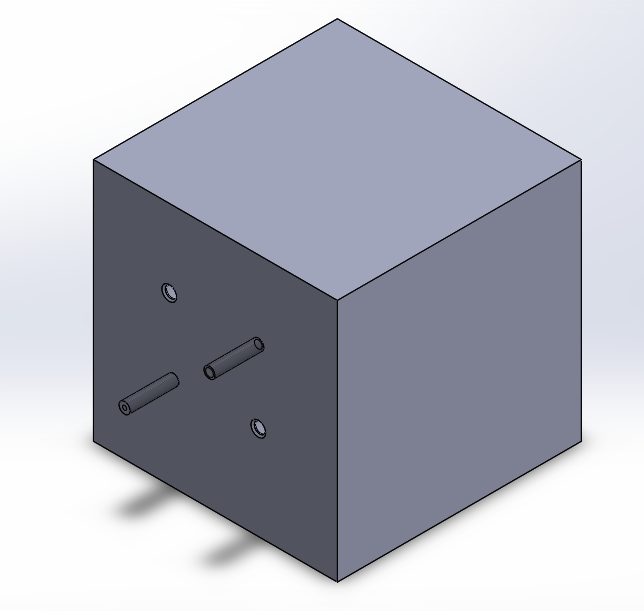
Figure 3. Screw design
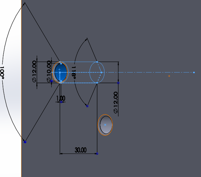
Figure 4. Measurements of the design
Simulation of the Fire Hose Design
The fire hose design came from the idea of a fire hose and its strength within the fire hose’s mechanical design. The designs from here on out are by Edward Villanueva.
The video bellow shows the simulation of the fire hose design. The connectors come together and twist until they lock in place. They can be untwisted and unattached using the same amount of force.
3D Printed Fire Hose Connector
We assumed this design would be successful, and ultimately it was. It’s large size caused an issue and thus it had to be reduced. Also, for better accuracy the slits would need to be larger. The image below shows the first print we did for the connector in ABS.
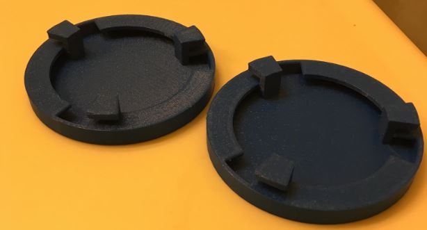
Figure 5. ABS print
Second Iteration
The image below shows a SolidWorks improved design using larger slits, continuing with the fire hose design while also doing a bottle cap implementation. There are threads within the connector to help lock it in place at a precise measurement. The threads also produce a stronger seal.
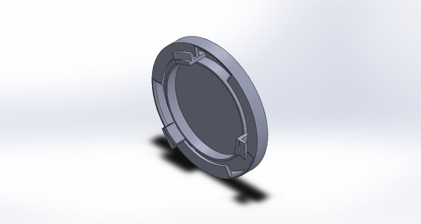
Figure 6. Second iteration of the connectors
Third Iteration
The design was improved by creating a larger space in the slit, as shown in the image below. Its purpose was to create a greater accuracy for when the connectors come together and close.
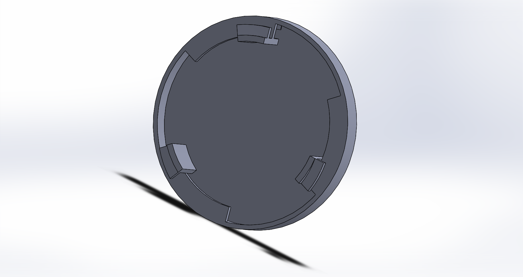
Figure 7. Connectors’ third iteration
Fourth Iteration
This design, shown in the image below, should have a greater accuracy to combine two connectors together since there’s a lot more smoothed surfaces and the gap between the threads that stick out are much larger than the previous gaps as the treads were reduced to two.
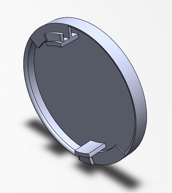
Figure 7. Fourth iteration of the connectors
Fifth Iteration
The image below shows the fifth and final design of the connectors. The circle in the center was added for the magnet or the steel plate, depending on if it’s the connector for the magnet or for the steel plate. If the connector is on Limbi then in the circle will be the magnet, if the connector is on the modules then the steel plate will go in the circle. The was also an outward ring added to the outside edge of the connector as well as tabs to disrupt the beam in the photo-interrupter. More information can be found in the Limbi: Cubic Modules blog post.
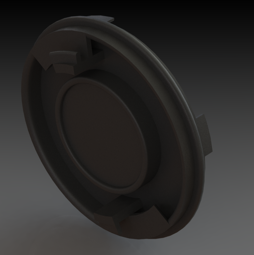
Figure 8. Connectors’ fifth iteration
Flower Petal Soft Lock
Shown below is the international NASA docking standard design for a “flower pedal” soft lock. They implemented soft permanent magnets and train like hooks. The idea behind this design is that the petal helps guide the connector in place, it turns, and locks in place via hooks. The reason we could not design this connector in time was because it has many electronic components for the small cubic module we have causing a significant size constraint. The documentation for the picture can be found by clicking the following: International Docking System Standard. The video shown below can by found by clicking the following: NASA Docking Test.
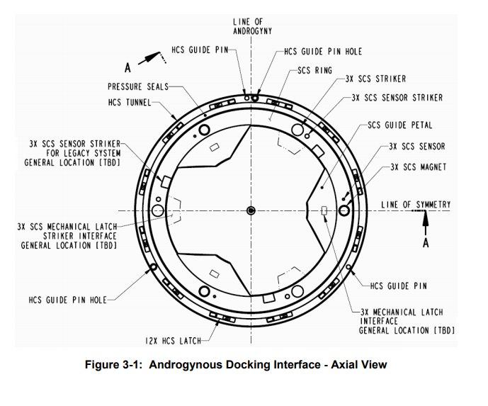
Figure 9. Flower Pedal NASA design

Video showing NASA’s flower petal design
We stumbled upon implementing the flower petal design and the fire hose idea. The reason we wanted to do the connectors this way was due to the fact that combining both ideas would reduce the need for too many electrical components within the cubic modules themselves. We were restricted on its size and weight due to our requirements. Below is the flower petal design made in SolidWorks however, it is incomplete because we ran out of time to think of an implementation between this design and our fire hose design.
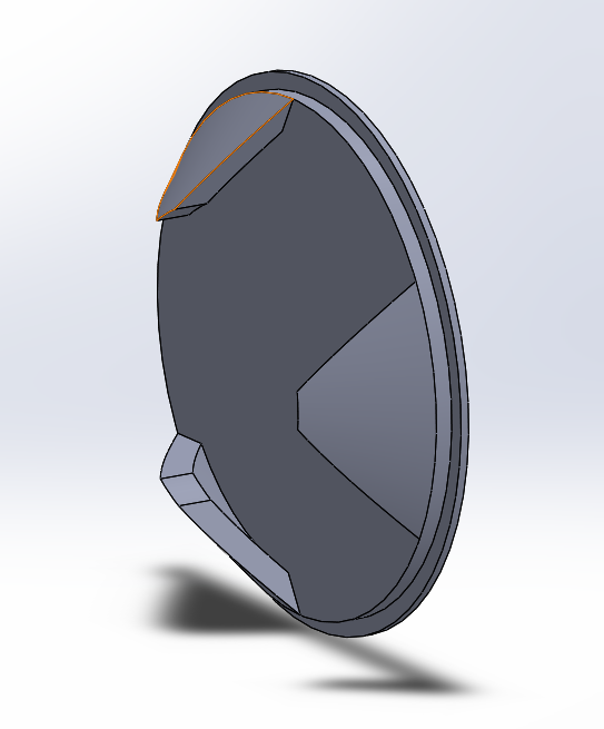
Figure 10. Flower petal connector design