Limbi Generation #2 Fall 2019
Limbi: Back of the Envelope Calculations-Torque
Author/s:
Alondra Vivas
Table of Contents
Introduction
The merger between the Electrical and Mechanical Engineering Departments started off with a proposition from Limbi Generation 2. The purpose of this merger between departments was to utilize the MAE department for back of the envelope calculations for the torque and for design ideas. Limbi Generation 1 told us they had a difficult time with the Servo Motors they used due to their torque. This was a huge motivator for us to meet with a professor within the MAE Department. We had 2 meetings with an MAE instructor on September 5th and September 13th. This post is dedicated to our proposition and the findings of the meetings.
Torque Calculations
The main reason we had the meeting with the MAE instructor was to have the instructor help us calculate torque. Limbi Generation #1 had a lot of trouble with the servos they used where the torque was not taken in to account which caused problems with the rotation of the limbs. We wanted to calculate the torque so that we wouldn’t encounter the same problem in the future.
During the meeting with the instructor, a suggestion was brought up to use differential gear motors where there is a single input divided in to 4 outputs. An issue with this idea was that we can’t have all 4 motors rotating at the same time we only need 1 motor rotating at a time.
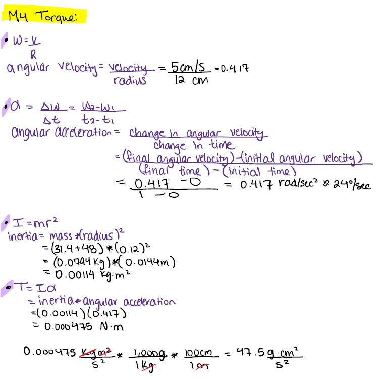
Torque was the main purpose of the meeting. It was suggested to do a calculation of frictional force multiplied by the radius and it was also mentioned that this is the same as frictional force between connectors multiplied by the pressure used to connect them. The professor suggested to use the following equation to find the torque: , where L is the acceleration needed to move and is the angular acceleration, alpha is the angular acceleration, and m is the mass of the motor. It was then stated the torque at joint 3 and 2 would be similar.
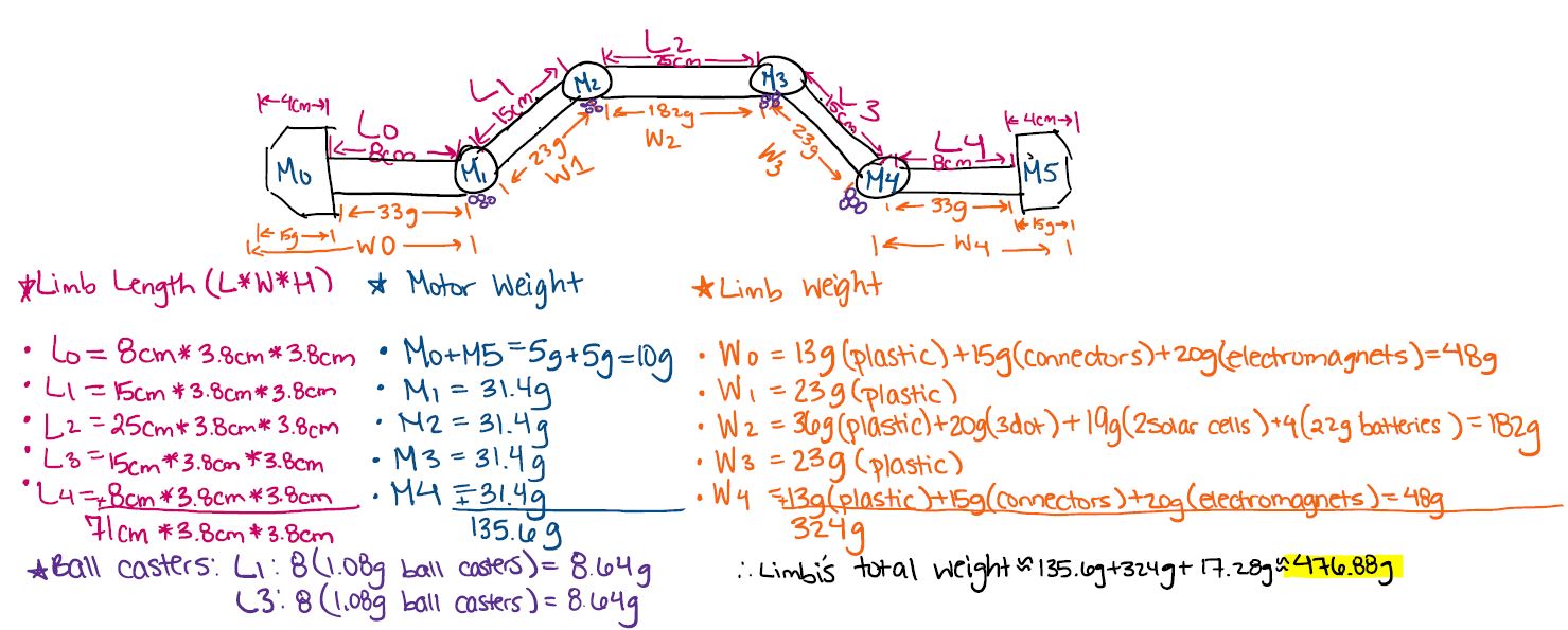
The picture below shows the calculations we made to calculate the expected weight of Limbi to find the torque.
Tips for Future Generations
During our proposition, the instructor was very engaged with our ideas by asking questions. We explained our mission objective which is to build autonomous structures in space using a multi-limb, multi-joint robotic arm. Its ultimate purpose is to build solar arrays, space stations, and laboratories detached from the space station. The professor was intrigued with the solar array idea noting that an improvement for future Limbi generations would be to add solar cells to the cubic modules creating a large solar array that can change orientation depending on the placement of the sun. This would be done by placing thrusters for the movement of the modules and solar sensors to better orient itself with the sun. Another interesting point was brought up where he discussed with us that the connector must me further indented within the modules so that when the modules close then can lay flat without any holes peeking through. We hadn’t designed the modules yet so this was good insight for before that design process began. All of these ideas might be helpful for future Limbi generations.
Conclusion
Limbi Generation #1 used servos. After calculating the torque, we realized that our Limbi is going to be very light weight due to our requirements and the way we would accomplish this is by 3D printing. This concludes that we can use motor with a high enough rated torque by finding the weight of that each limb to calculate the torque.
Since we only have 16 weeks to do this project, we had to start rapid prototyping at an early stage. The MAE students were about a month in to the semester when they picked their senior design projects and teams. By that stage we were already 3D printing our SolidWorks models, purchasing the motors, and decided on purchasing ball caster for the low friction surface requirement instead of the hockey table. This created a situation where we did not need the assistance of the MAE department any longer. Therefore, while the meetings were productive the scheduling of the two departments did not match.


