Limbi Generation #2 Fall 2019
Limbi: Critical Design Review
Table of Contents
Project Objective/ Mission Profile
By: Alondra Vivas
Project Objective
We plan to continue the advancement of NASA JPL’s Limbi and Limbi Generation #1, a multi-jointed robot that allows for the connection of two modules through their docking mechanisms. The goal is to improve on the current Limbi by developing a mechanical androgynous connector for Limbi as well as the cubic modules, reduce the overall size and mass of NASA JPL’s Limbi by 50%, allow power transfer to flow from the cubic modules to Limbi, replicate space by creating a low friction environment, and reducing the cost of the overall project.
Mission Profile
The purpose of Limbi is for astronauts to create structures autonomously in space that would reduce the time, risk, and cost of building the structures. Utilizing the idea of Legos, the cubic modules can be used to build space stations, large solar panels, and space laboratories for safer and more efficient experiments.This would be accomplished by having Limbi pick up one cubic module with its connector, attach it to another cubic module while remaining attached to the second cubic module,the next step would be to pick up another cubic module and repeat the process over again.
The Design
Limbi Exploded/Annotated View
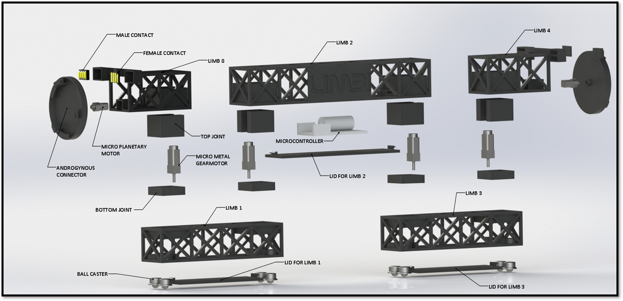
The detailed design portion of Limbi is shown below. In this image, the exploded view can be seen as well as the annotated view that names every component within Limbi.
- Limbi consists of 4 micro metal gear motors placed at each joint; they are placed within the joints via press fit.
- There are 4 ball casters on the bottom of limb 1 and 3 which are placed there also through press fit.
- A lid has been designed to go under limbs 1, 2, and 3 to access the electrical components within Limbi quicker.
- The PCB is placed inside limb 2.
- Power transfer contacts were added to the top outer edges of limbs 0 and 4 so that when the connector comes in contact with the module’s connector power can flow from Limbi to the modules.
- The micro planetary motors and press fit on a motor mount within limbs 0 and 4. They control the rotation of the androgynous connectors.
- The androgynous connectors of Limbi are on the outer limbs. The motor’s shaft is press fit in to the motor to make it rotate.
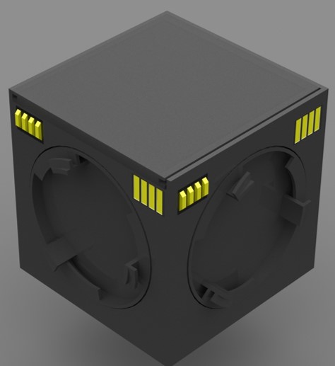
The detailed design portion of the cubic modules is shown below. In this image, the exploded view can be seen as well as the annotated view that names every component within the modules.
- The modules consist of 4 micro planetary motors placed at motor mounts.
- The shaft is in the back of the connector to allow them to rotate via press fit.
- There are 4 ball casters on the bottom of the modules on each corner which are placed there also through press fit.
- A lid has been designed to go on the top face of the cubic modules to access the electrical components within.
- The PCB is in the middle of the module.
- Power transfer contacts were added to the top outer corners of the module so allow power transfer to occur between Limbi and the modules.
Project Features/ Innovative Ideas
Androgynous Connectors
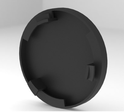
A requirement we had was to create a system of connection that is androgynous. Meaning both male and female, a system that no matter what side of the cubic module Limbi grabs, it can still connect to other modules. For the design, we first used the idea of Limbi Generation 1 where they had a connector on each end of Limbi. Then, we placed a connector on 4 faces of the module except the top and bottom.
Another requirement we had was to have the arm be able to lock the modules together through a mechanical design without power. The solution found was to implement a fire hose design with a bottle cap thread to create a tighter seal.
Cubic Modules
The cubic modules are considered the “building blocks” of Limbi, due to their ability to create structures in space by the user staking them in any position required to create the final structure. As seen on the section within this blog post titled, “Modules Exploded/Annotated View,” there consists of a detailed explanation of why this module is an innovative design.
Performance Requirements
By: Alondra Vivas
Our requirements did not change from the PDR.
The second generation Limbi follows the Level 1 requirements of the first generation Limbi with a few adjustments, to compare see Limbi geration 1 requirements. These requirements must be accomplished while also taking in to consideration that this project is meant to be used in space.
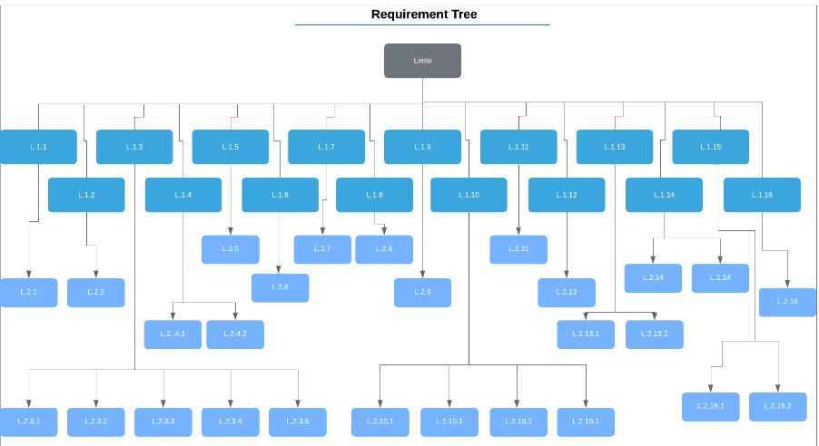
The picture below is a requirement tree showing how Limbi Generation 2 is neither over designed nor undersigned.
Level 1 Program and Project Requirements
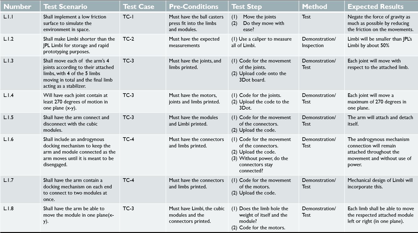
L.1.1) Shall implement a low friction surface to simulate the environment in space.
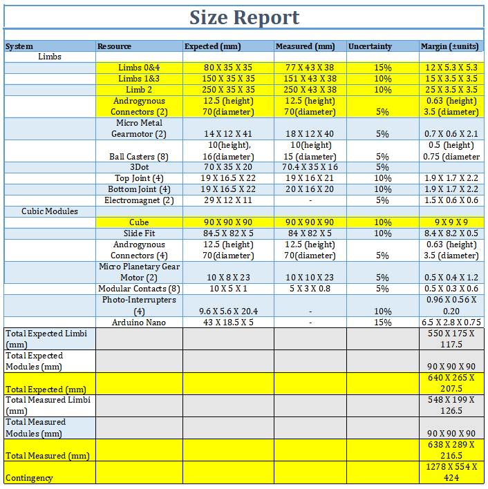
L.1.2) Shall make Limbi Shorter than the JPL Limbi for storage and rapid prototyping purposes. Limbi will be smaller by approximately 50% of the original size of the JPL design.
L.1.3) Shall move each of the arm’s 4 joints according to their attached limbs, with 4 of the 5 limbs moving in total and the final limb acting as a stabilizer.
L.1.4) Will have each joint contain at least 270 degrees of motion in one plane (x-y).
L.1.5) Shall have the arm connect and disconnect with the cubic modules.
L.1.6) Shall include a docking mechanism to keep the arm and module connected as the arm moves until it is meant to be disengaged.
L.1.7) Shall have the arm contain a docking mechanism on each end to connect to two modules at once.
L.1.8) Shall have the arm be able to move the module in one plane (x-y).
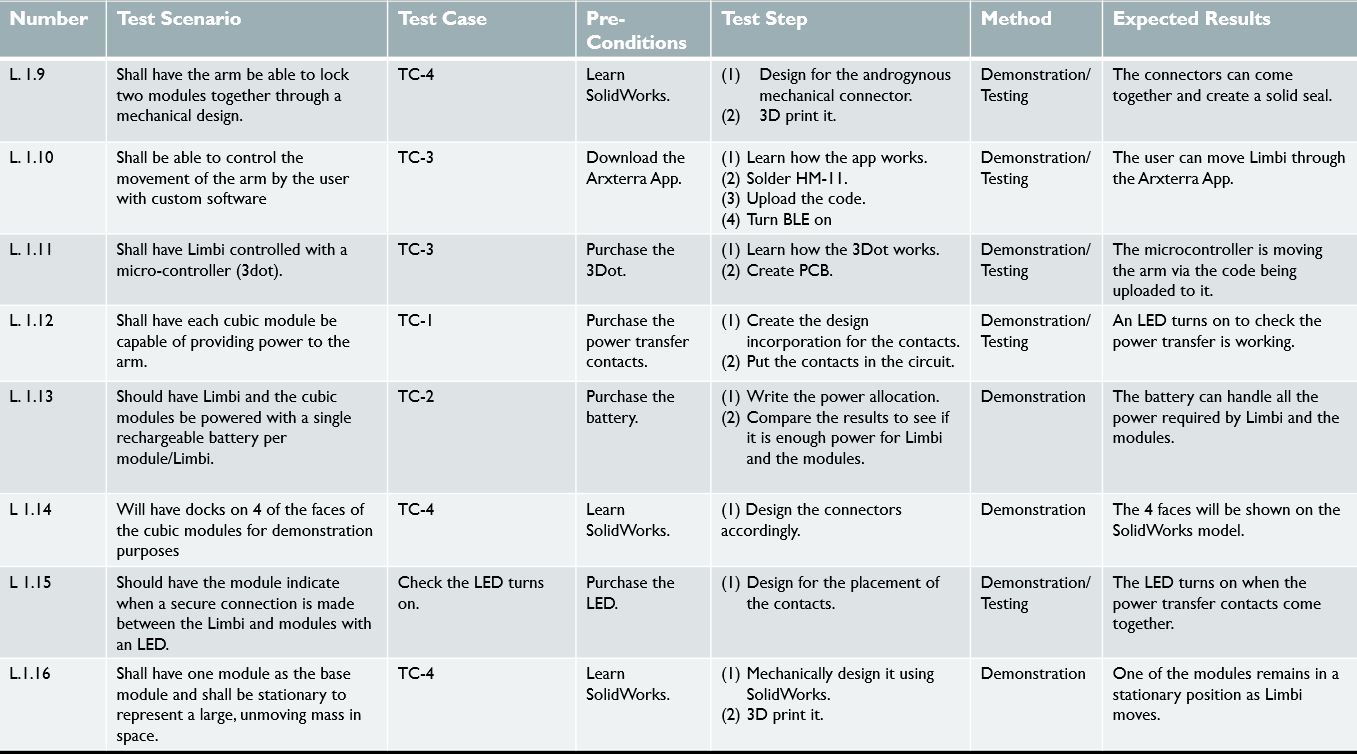
L.1.9) Shall have the arm be able to lock two modules together through a mechanical design.
L.1.10) Shall be able to control the movement of the arm by the user with custom software.
L.1.11) Shall have Limbi controlled with a micro controller (3Dot).
L.1.12) Shall have each cubic module be capable of providing power to the arm and to the other cubic modules.
L.1.13) Should have Limbi and the cubic modules be powered with a single rechargeable battery per module/Limbi.
L.1.14) Will have dock on 4 of the faces of the cubic modules for demonstration purposes.
L.1.15) Should have the module indicate when a secure connection is made between the Limbi and modules with an LED.
L.1.16) Shall have one module as the base module and shall be stationary to represent a large, unmoving mass in space. This requirement is base on Section 4 of “An Untethered Mobile Limb for Modular In-Space Assembly.”
Level 2 Program and Project Requirements
L.2.1) Limbi will be supported with 8 small nylon metallic ball casters (each weighing 5.0g) on Limb 1 and Limb 3 to simulate the conditions where the arm will not be affected by gravity.
L.2.2)Limbi will follow the form factor of the JPL version; the lengths will be optimized in respect to inverse kinematics.
L.2.3.1)Each joint shall control 2 limbs at a time.
L.2.3.2)Joint 1 shall control the motion between Limb 0 and Limb 1.
L.2.3.3)Joint 2 shall control the motion between Limb 1 and Limb 2.
L.2.3.4)Joint 3 shall control the motion between Limb 2 and Limb 3.
L.2.3.5)Joint 4 shall control the motion between Limb 3 and Limb 4.
L.2.4.1)Limbi will have 4 joints controlled by micro metal gearmotors.
L.2.4.2)Each micro metal gearmotor shall require no more than 6V to run with a load.
L.2.5)The docking mechanism shall consist of the mechanical androgynous connector described, to allow Limbi to successfully attach and detach to and from the module.
L.2.6)Only 1 docking DC motor shall be in motion at once, so the module does not un-dock while the other module docks.
L.2.7)The docking mechanisms on each end will be identical to each other.
L.2.8)The micro metal gearmotors shall be able to provide more than 2.5 kg.cmor 0.245 Nm based on the force to move an object in a planar field.
L.2.9)The mechanical design of the connectors must be strong enough so that constant power from electromagnets are not required to attach or detach them.
L.2.10.1)The user interface shall utilize wireless Bluetooth to control Limbi.
L.2.10.2)The custom software will be implemented through the Arxterra App.
L.2.10.3) The user interface shall have push buttons/toggles for pre-determined movements.
L.2.10.4) The user interface shall use simulated sliders for manual movements.
L.2.11) The project will use a 3dot board mounted within the Limbi arm to allow the 4 micro metal geared motors and 2 micro planetary motors to be controlled directly by the microcontroller.
L.2.12) The power provided from the module shall come from a battery (5V) via the docking mechanism.
L2.13.1) The battery for limbi shall be capable of providing 1055 mA current (if needed) which will be used to power the 3dot, the motors, and the electromagnets.
L.2.13.2) The battery used will be a rechargeable Lithium Ion battery weighing 22g each and using 1.5V each.
L.2.14.1) The module shall have an androgynous connector on all 4 faces, with the top and bottom faces remaining empty to allow ease of access to the electronics within, and for a location for the casters.
L.2.14.2)4 faces on the cubic module will serve for both interconnections among each other and to connect to Limbi.
L.2.15.1) The LED on the module should be activated by one of the four power connections. Verification through testing.
L.2.15.2) The LED should be on the corner so the person controlling the app can easily see that a secure connection has been made. Verification through demonstration.
L.2.16)The arm shall be attached to a module at all times. Verification through demonstration.
Testing Methods
The following is a list of the Level 1 requirements being analyzed, its test scenario- which indicates the full requirement, what test case it follows- the more in detail cases can be found on the bottom of the blog post, pre-conditions that have to be met in order to accomplish the test, any general test steps, what method is used, and any expected results. The importance of creating this list was so the team has a clear idea of how to accomplish all the requirements. They are shown in the images below.
Engineering Standards & Constraints
- The Limbi shall employ a custom PCB to extend the functions of the Arduino Nano and the 3Dot by allowing control of 4 micro metal geared motors, 2 micro planetary motors, 2 electromagnets, and Arduino Nano communication.
- Disassemble and Reassemble of the robot shall be constrained to less than 20 minutes (10 minutes+10 minutes).
- The Limbi shall be completed by the date of the final: December 17th 2019.
- The robot shall be designed in such a way that there are no dangling or exposed wires via cable wrap.
- The form factor of Limbi shall be constrained by the original JPL version.
- The usability of the Limbi shall be enhanced by use of the Arxterra phone and control panel application
- The ArxRobot app shall allow control of all joint motors and docking motors (see requirement L 1.10)
- Manufacturability of 3D printed robots shall minimize the number of files to be printed when using the library’s Innovation Space to print the final robot.
- All Lithium (Li-ion, Li-polymer) batteries shall be stored, when not in use, in a fire and explosion proof battery bag.
- Software shall be written in the Arduino De facto Standard scripting language and/or using the GCC C++ programming language, which is implements the ISO C++ standard (ISO/IEC 14882:1998) published in 1998, and the 2011 and 2014 revisions.
- The Limbi shall be controlled via Bluetooth 4.0 in compliance with the Bluetooth Special Interest Group (SIG) Standard (supersedes IEEE 802.15.1).
Systems/Subsystems Design
System Diagram
By: Colin Rogers
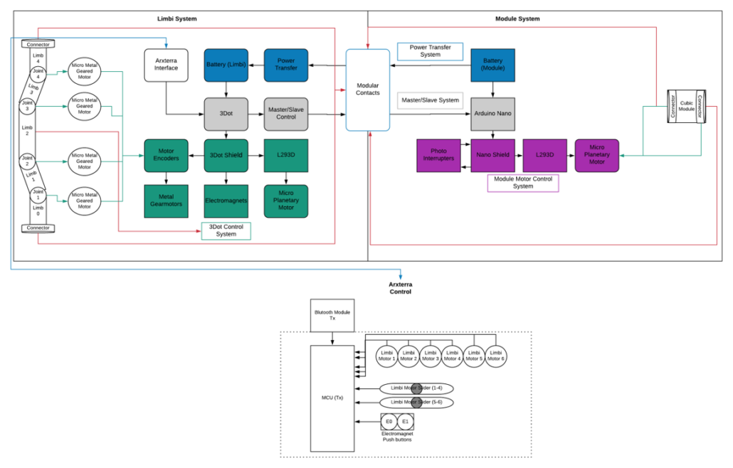
The system diagram improved from the PDR by adding the mechanical components.
Limbi Generation #2 consists of two separate systems: Limbi and the cubic modules. Limbi contains the Arxterra Interface, and 3Dot Control System, Arxterra control, and the arm of Limbi’s mechanics. The module’s system is made up of 4 main categories: power system transfer, master/slave system, module motor control system, and the module’s mechanics. It is further broken down in the image below.
Wiring
Cable Tree
By: Alondra Vivas
The truss design within Limbi created a possibility for the wires within it. Our quick solution was to use heat shrink wrap, therefore, the wires exits the motors and we take it out to go outside the truss design followed by guiding the wires to connect within limb 2 where the PCB is placed. This solution did not work as the heat shrink wrap is too stiff and from an aesthetics perspective it didn’t look pleasing to the eye. Below is the cable tree we created to solve the solution of having the wires stay hidden within Limbi. As one can see, the GND and VCC wires coming from the connectors will have cable wrap when they intersect with the GND and VCC wires of the micro planetary motors. The micro metal geared motors’ wires also will have cable wrap and will connect with the connector’s and the planetary motor’s cable wrap. The wires will go down joint, 1 and 4 through Limbi 1 & 3, and then back up joints 2 and 3. Cable wrap will then connect the geared motors’ wires to the other wires that went up the joints while being guided to the PCB. The actual cable wrap will be spaghetti wire insulation tubing which possesses the minimum coefficient of friction of any known solid by being made of Teflon. The link to the cable wrap can be clicked here: Cable Wrap.
Wiring Solution
By: Edward Villanueva
In order to get the wires to go through limbi, the have to go through the joints. A design solution was created specifically for the wires where we made the joints of Limbi partly hollow to allow room for the wires to pass through. The joints for the micro metal-geared motors contain a top and bottom piece, to hold the base of the motor and the shaft of the motor in place. The motor fits on the top and bottom piece via press fit. The wires for the motor come out the top and will flow down into the hollow part, go through the entire limb until it reaches the next joint where it will go up the joint’s hollow piece. This causes the wires to remain hidden within Limbi.
ArxRobot APP Customization
By: Edward Villanueva
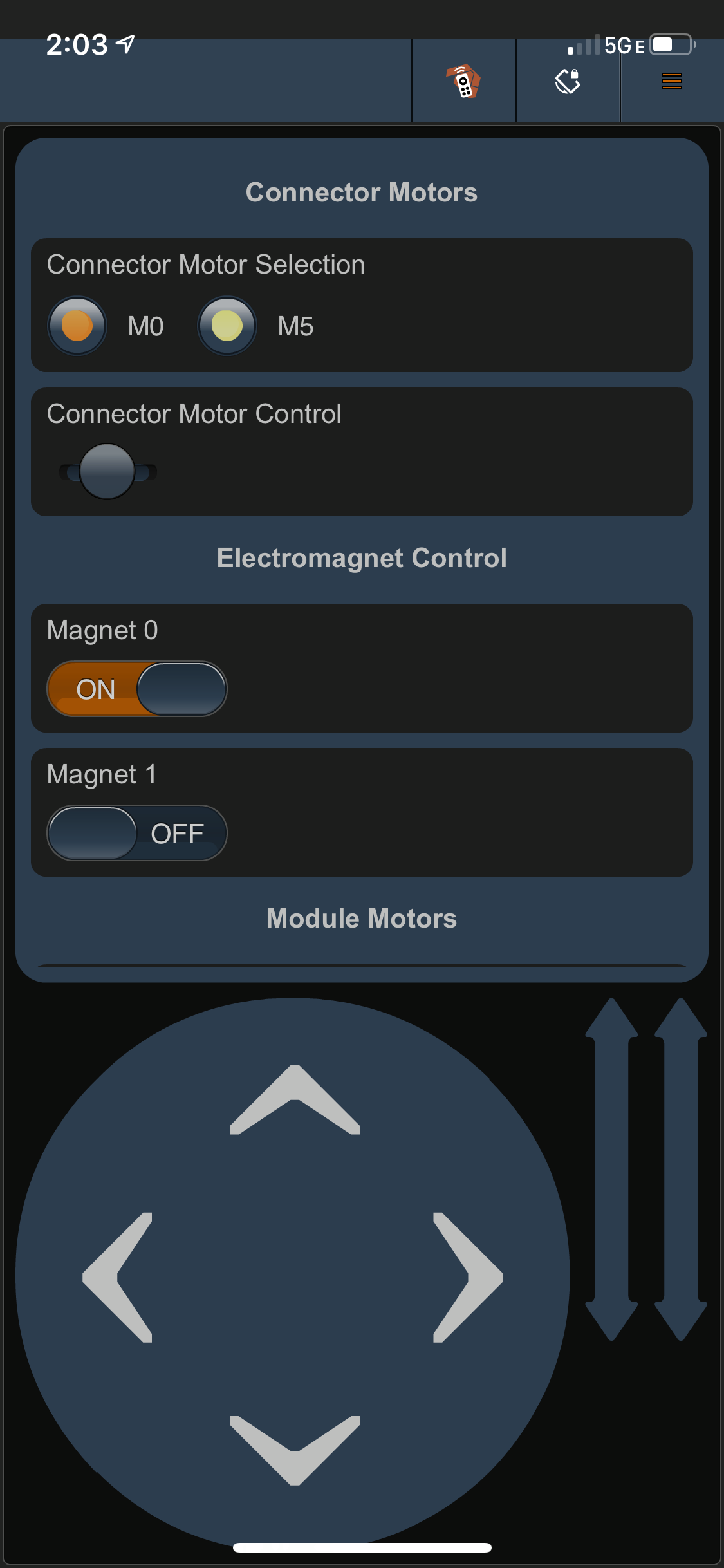
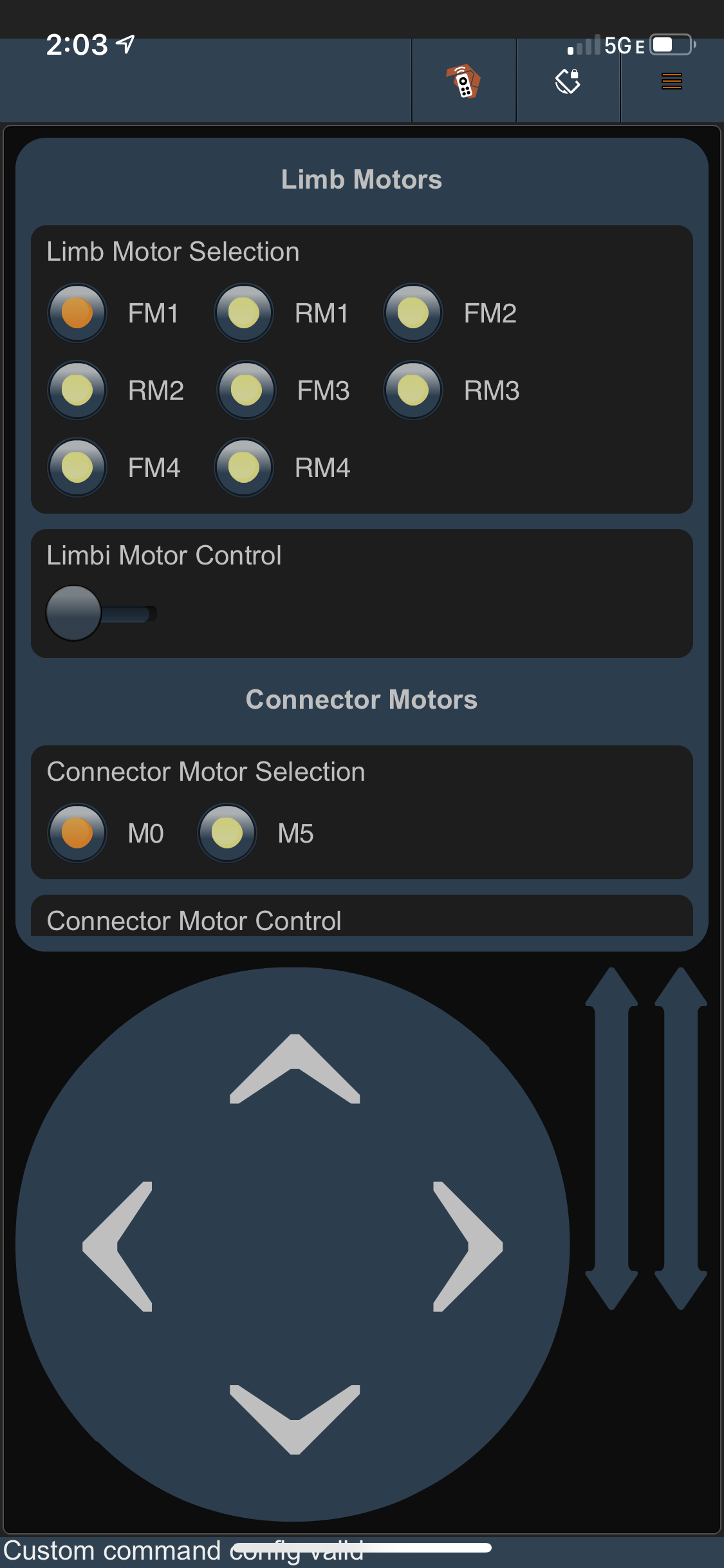
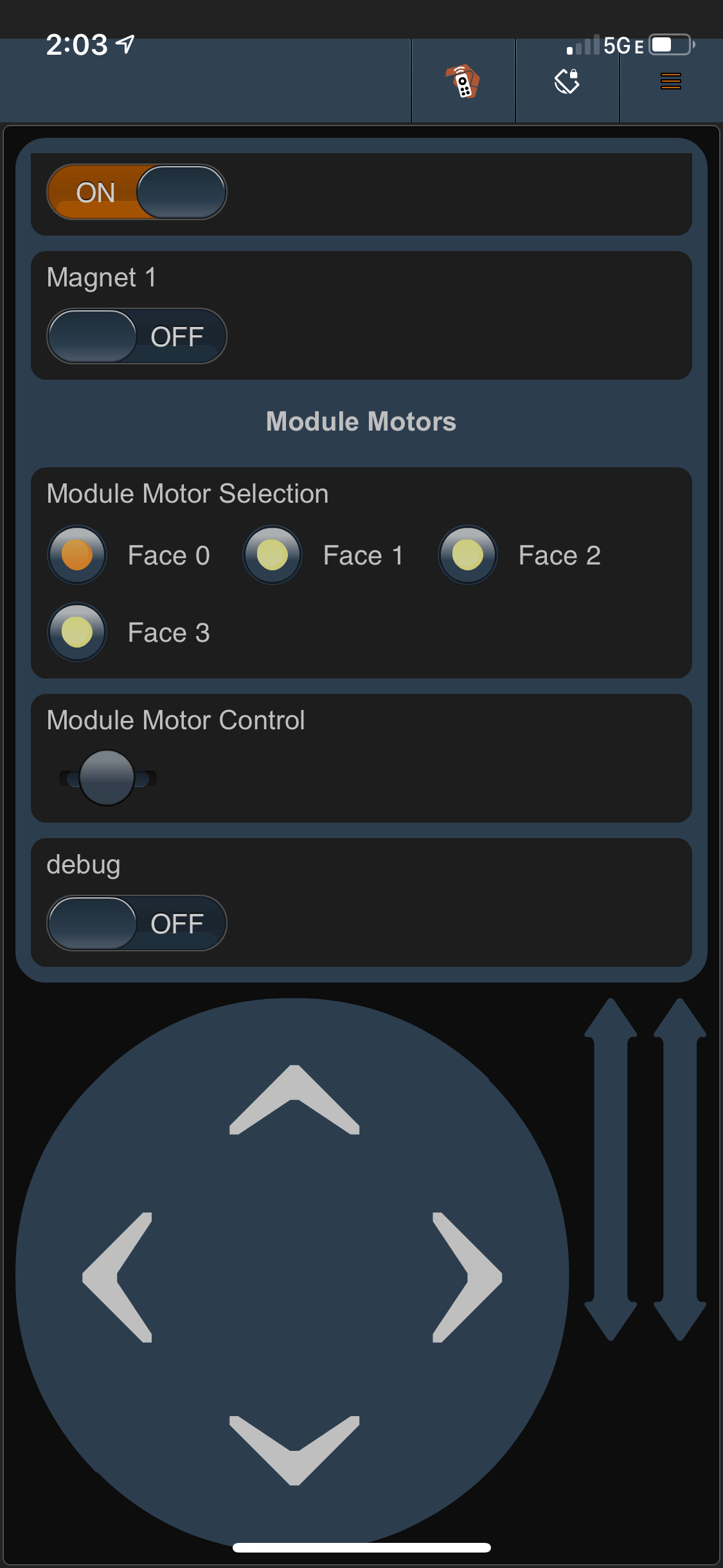
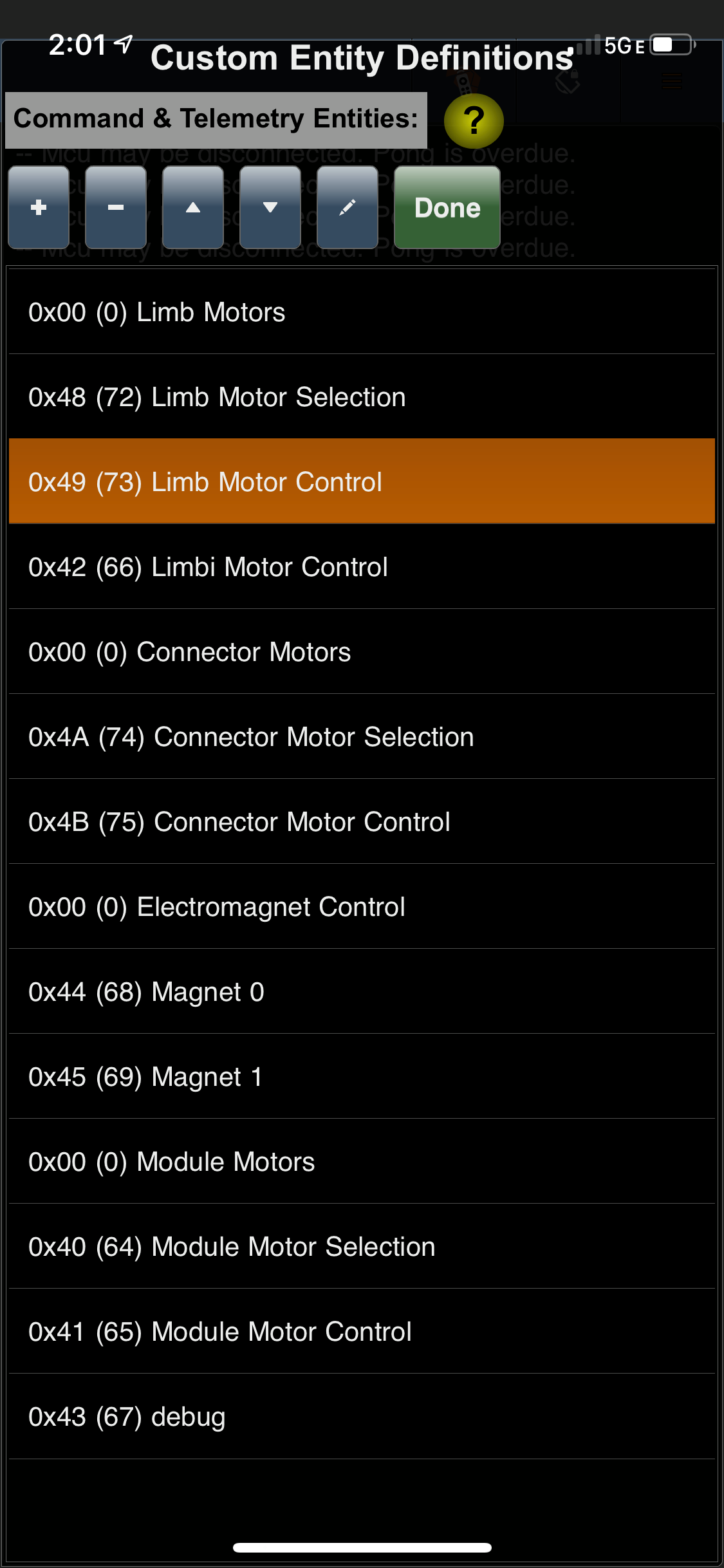
The app will feature custom commands to allow for full 270 degrees of motion on the Limbi joint motors and 360 degrees of motion on the androgynous connectors. It also will contain electromagnet Boolean values to turn them on and off accordingly. A big part of the App’s customization is to allow for control of module androgynous connectors, once contact has been established between the modules and Limbi. The final App will contain 9 total custom commands.
Mission Command & Control Code
By: Edward Villanueva
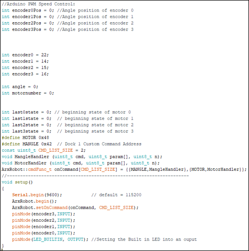
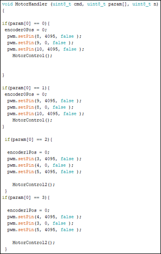
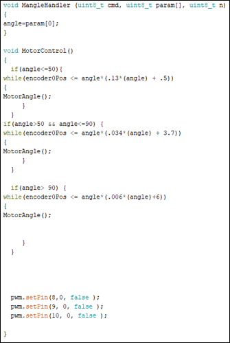
Below is the code for the the initialization of our custom variables and custom commands for the Arxterra app near the bottom. We currently have two custom commands defined, one for choosing the motor angle, and the other for choosing the motor itself. The initialization variables are meant to set the starting angles, motor chosen, and encoder position all to zero, so that they may be called upon later in the code.
Electronics System Design
By: Colin Rogers
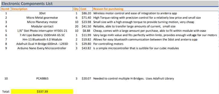
The image below illustrates the Electronics components list. It shows the component name, quantity, cost, reason for purchasing, and the total cost of just the electronics components. The links are in the References/Resources section of this blog post found at the bottom.
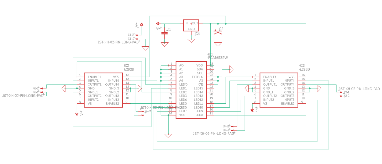
PCB Schematic
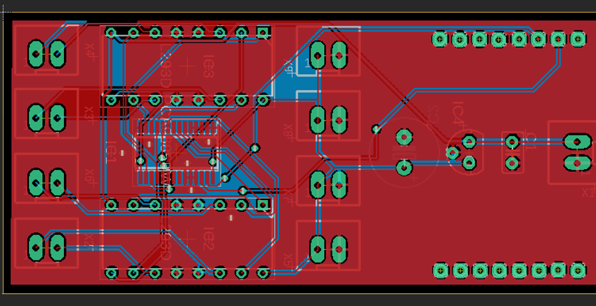
PCB Layout
Mechanical Design
Limbs
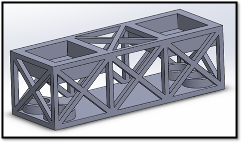
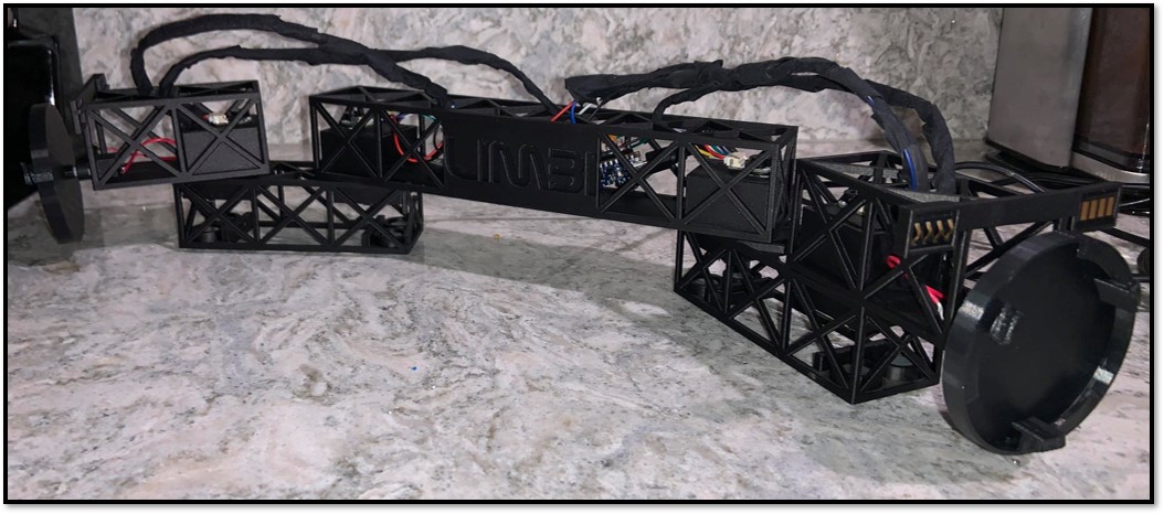
Truss designs are a big part of space architecture; it was implemented into Limbi Generation #2 due to it reducing the size of the and durability. Ball casters were incorporated onto the bottom of limbs 1 & 3 to mimic a low gravity environment by reducing the surface friction. The mechanical design has changed a small amount since the PDR. In the PDR, the design was a triangular truss design. However, we decided to change it to a rectangular truss design to allow more space for the micro controller. Also, we added the name Limbi in NASA font on the front of limb 2.
Sleeve Design
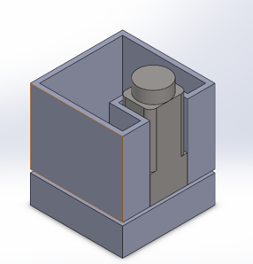
The sleeve design will allow for ease of entry of the androgynous connector through the front face. It’s meant to retain androgynous connectors in place, while simultaneously removing the load off the micro planetary motor that will rotate the connector. This design has been implemented within the newest version of the modules. A design problem is that nothing is stopping the connectors from falling out of the sleeve, also there is still a lot of load on the motor. A blog post has been created that discusses the solution.
Rapid Prototyping, Initial Prints, & 3d Printing
3D Printing Problems
We printed our project in the Innovation Space Center. They are reliable and offer a discount to students. However, come unforeseen issues we encountered with them was that they were behind on the prints for about 2 weeks for the V2 demo. We had to speak to the director of the Innovation Space Center and tell her our concerns with the late work being printed. A blog post has been created that talk about this in more detail as well as the material we used. We tested the prints in Onyx material and ABS. Onyx produces a sturdier, cleaner looking material but is the most expensive material they have. ABS is cheaper than Onyx while having less friction than onyx. A big advantage of ABS is the dissolvable supports
Rapid Prototyping
Connectors
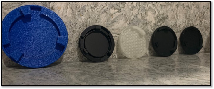
The picture below shows the several iterations of our connectors. The one on the left was our first iteration and very first 3D print for this project. It was printed in ABS. Problem encountered was the large size. The second one from the left was our second iteration. It was printed in Onyx. Problem encountered was the middle ring. Middle connector was our third iteration. It was printed in nylon. Problem encountered was that the material was too bendy, and the shaft housing was too large. Last 2 connectors were our fourth and fifth iteration, respectively from left to right. The last connector was made from ABS the fourth one from Onyx. They were printed at similar time. We are going to go with the Onyx connector.
Cubic Modules
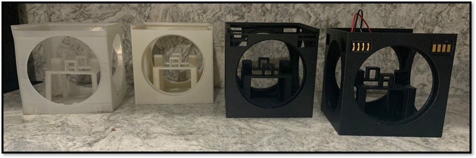
The picture below shows the several iterations of our cubic modules. The first iteration of the cubic modules is not pictured above because it was misplaced. It was printed in Onyx and did not contain the press fit housing for the motors. The module on the left was our second iteration which was used for our V1 demo. It was printed in Nylon to save money and time; however, it was printed poorly. The second module from the left was our third iteration. It was printed in ABS. It lacked the press fit housing for the modular contacts. The third and fourth modules are our fourth and fifth iteration, the only difference between the two being that the fourth iteration is in onyx while the fifth is in abs.
Limbi Iterations
Version 1
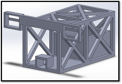
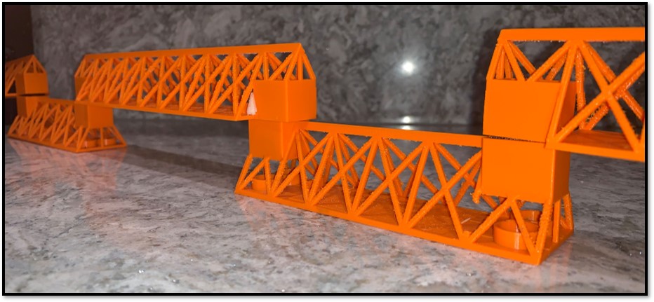
Limbi Version 1 utilized a triangular truss design. It was printed in ABS, a problem encountered with the triangular truss design was that the 3D printer had an issue with the angles which caused a poor print also the 3Dot couldn’t fit. The color was chosen as orange in order to get into the Halloween spirit since our demo was in October.
Version 2
Verification Test Plan Overview/ Experiment Results
Verification Test Plan Overview
The test cases for Limbi Generation #2 were split in to 4 different test cases.
- Test Case 1: A visual test will be implemented to help negate the effects of gravity on Limbi and the cubic modules. This test also will determine if power transfer has been initiated due to an LED lighting on.
- Test Case 2: A comparison test between the allocations from Limbi Generation 1 and Limbi Generation 2 will be done to view the size and weight comparison. This will also be used to determine appropriate power being supplied to Limbi.
- Test Case 3: A motion test will be done to test for the angle accuracy, and to see if that motor is strong enough to rotate multiple limbs. This will be done using the ArxRobot App and the assistance of the 3Dot.
- Test Case 4: These tests will be through inspection. The SolidWorks design’s simulation and 3D prints are a visual test proving that the design works.
Power Transfer Test
To determine that the power transfer contacts were operational, a power transfer test was done. We accomplished this by soldering an LED to the back of one of the contacts of Limbi. We also soldered a wire to the back of one of the cubic modules’ contacts to then attach it to a power source. The conclusion was that since the LED turned on upon impact, the contacts are working properly, and the mechanical design implemented for the position of the contacts is successful.
Micro Geared Motor Angle Test
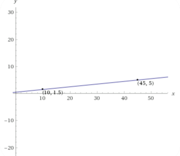
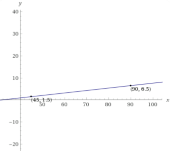
In order to get the Micro Geared Motor to turn to a specific angle a test of trial and error was performed. Points were plotted in order to derive the equations. The reason this had to be done was because we could not understand why the motors were not turning at the specific angle we gave it. As a quick solution we did these graphs to figure out what value to give the motor.
Updated Project Status
Mass Report
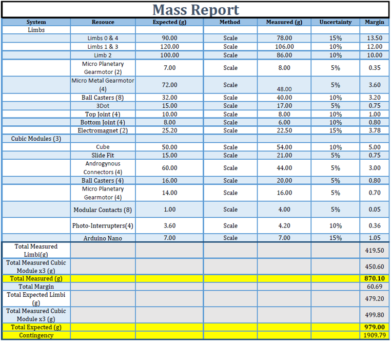
The mass report is shown below. It illustrates how the measured mass of Limbi is currently 419.5g, the mass of the combination of all 3 cubic modules is 450.6g, making the overall measured mass of this project 870g. We are expecting it to increase because not every component has been purchased thus far.
Size Report
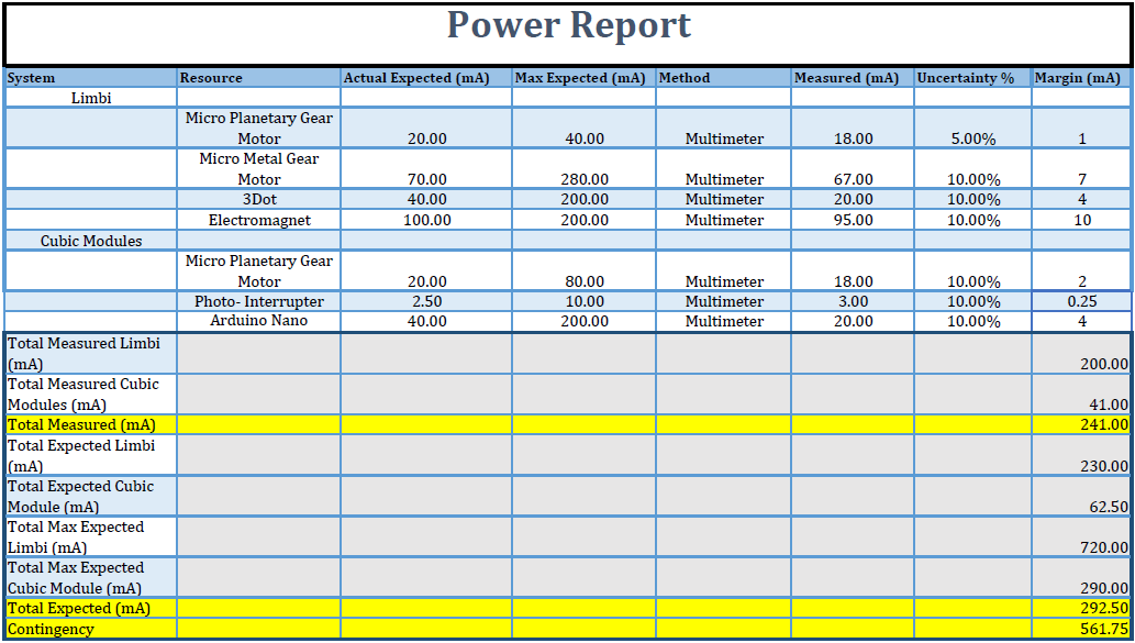
Power Report
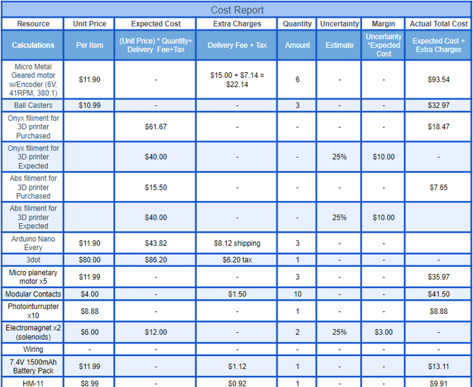
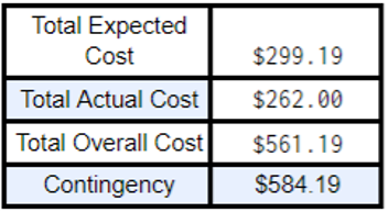
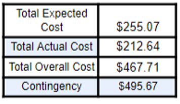
Cost Report
Burn down Report
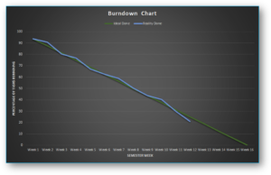
The project is currently at 79% completion. The things that need to get done before the V3 demo are:
- Final Documentation
- Master Control Software
- Slave Control Software
- Photo-Interrupter Code
- Photo-Interrupter Test
- Solenoid Test
- Finalized Purchases
- Code for the Motors at the Connectors
- Code for the Photo-Interrupters
- Limbi V3
- Connectors V6
- Cable Wrap
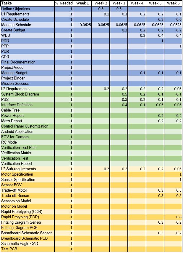
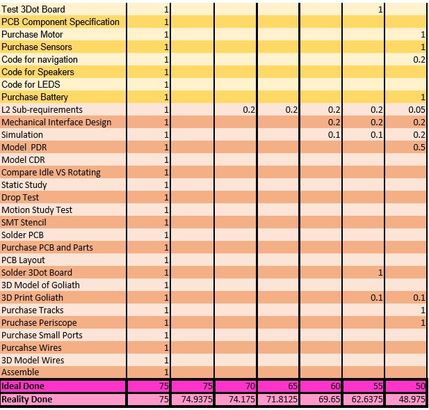
A picture of the project’s progression is show below. It details all the work done from week 1 up until week 16. The chart is split into 4 separate sections where the blue section is work for the project manager such any documentation required, the purple section is for the purchases and testing, the green section is for electronics, and lastly the orange section is for the mechanical design of the project. Some items take several weeks to complete, therefore, the % accomplished column has the percentage completed of that row’s task.

