Limbi Generation #2 Fall 2019
Limbi: Cubic Modules
Author/s:
Alondra Vivas
Edward Villanueva
Table of Contents
Purpose of the Cubic Modules
The cubic modules are the “building blocks” of the project which has become an important project feature, or innovative design. Utilizing the idea of Legos, the cubic modules can be used to build space stations, large solar panels, and isolated laboratories for safer and more efficient experiments in space. The way this is done is by having Limbi pick up one cubic module with its connector, attach it to another cubic module while remaining attached to the second cubic module, the next step would be to pick up another cubic module and repeat the process over again.
Inner Module Design Ideas
This section analyses the several iterations we did for the cubic modules. The main reason for the iterations were adding motor mounts, adding the placing for the power transfer contacts, and the placing of the photo-interrupters. All Solid Works models were designed by Edward Villanueva.
First Iteration
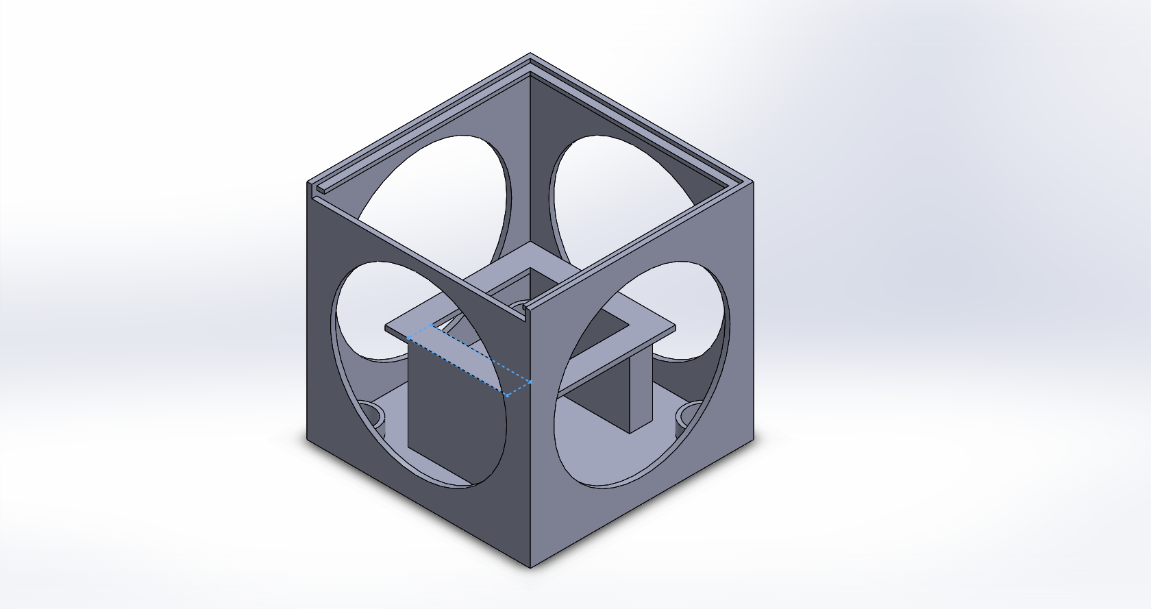
The first iteration of the modules’ design purpose was to create a place where the arduino nano could go. A table was thought of so that the following iteration could have the motors lay right on top of the table. However, it was missing a few key features including a design to hold the motors in place, as well as a a sleeve to hold the connectors in place from falling too far forward or backward. In addition, the press fitted holes on the bottom of the cubic modules, were far too large, rendering the idea of the press fit unusable. On top of this, the electronics enclosure in the middle took too much free space, limiting the size and amount of components that would be able to be placed within the modules themselves.
Second Iteration
The second iteration of the modules has the ball casters implemented on the bottom face. There are 4 ball casters, one on each corner and they are press fit. Then, motor mounts were created on top of the table to hold the motors in place; however, contrary to the first iteration where the electronics enclosure was too narrow, the design of this motor mount platform had legs that were far too thin, resulting in structural instability and as a result the platform’s legs would easily come off. In addition this version of the module was still missing a sleeve that would refrain the connectors from moving forward and back. The ball casters fit perfectly via press fit in this iteration.
Exploded/Annotated View
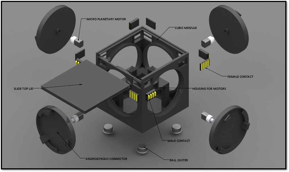
The annotated view below displays the 2nd version of our cubic module along with an early design of the connectors themselves. This design lacks the modular contacts in the corners, however it still contains 4 ball casters, 4 connectors, 4 motors and the same motor mounts used in later designs.
Third Iteration
Power Transfer Contacts Design
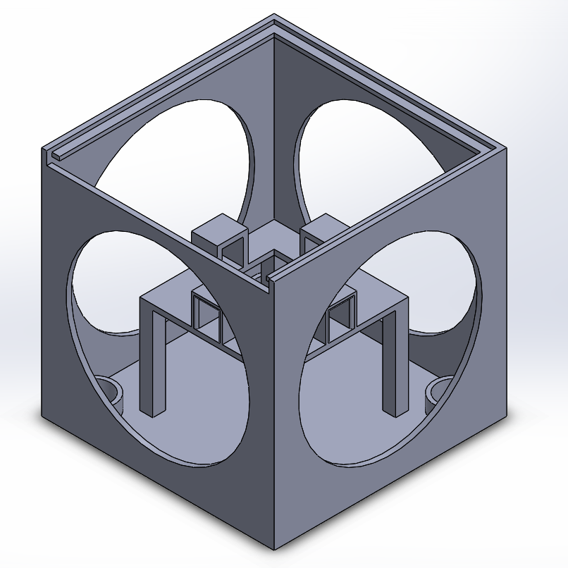
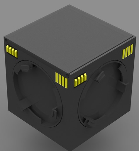
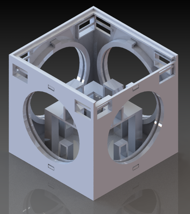
The third iteration of the cubic modules featured a press fit design for the modular contacts on both of the upper corners of the front, right, left, and back faces of the module. Each corner was designed to hold either a male or female contact, and a back post was implemented to ensure that the connectors wouldn’t fall back into the module, while still allowing for full access to the wiring of the contact’s back sides. This design was near the final product, however the issue of the sleeve design was finding a location for the photo interrupters, therefore, this still needed to be addressed in a future iteration.
Sleeve Design
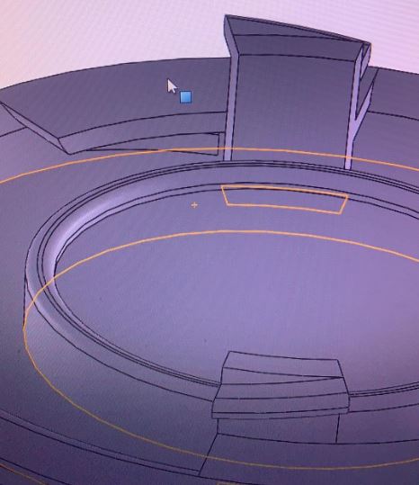
This early sleeve design was meant to retain the androgynous connectors in place while simultaneously taking the load off the micro planetary motors, that allow for rotation of the connectors. This initial design only featured an inside sleeve, preventing the connectors from being pushed too far inside during the docking process, however; this still allowed for the connector to fall forward, which is a prevalent problem during the docking process. The image can be seen below as the outer dented circle where the connectors would be.
Exploded/Annotated View
The annotated view below displays all the various components nested within the cubic module (V3). We can see that it features a total of 4 ball casters, 4 connectors, 4 motors, and 8 modular contacts within a 9 by 9 cm cube. In addition to this, we can see both the platform for the motor mounts as well as the electronics enclosed directly below it.
Fourth Iteration
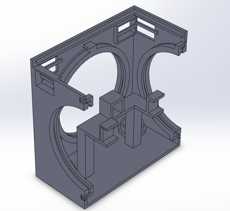
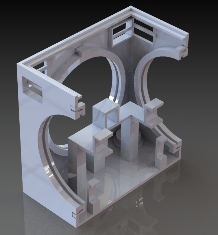
The final iteration of the cubic modules saw a press fit design for the photo interrupters themselves, located near the base of the cubic modules, which will allow for the connectors to rotate freely as the photo interrupter never makes contact with the connectors. There has also been the implementation of a removable sleeve design, allowing for the connector to be fully encased with no possibility of the connector itself being pushed too far back or forward during the docking process.
Sleeve Design
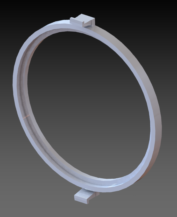
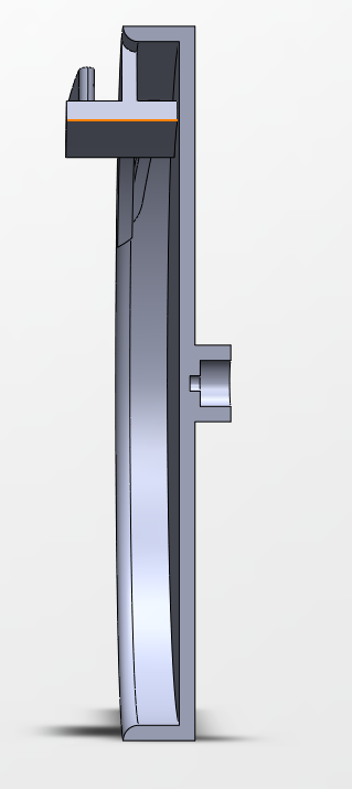
The sleeve design is meant to retain the androgynous connectors in place while simultaneously removing the load off the micro planetary motor that will allow for the rotation of the connector. This design will allow for an ease of entry for the androgynous connector through the front face.
Back of the Connectors
Shaft Press Fit
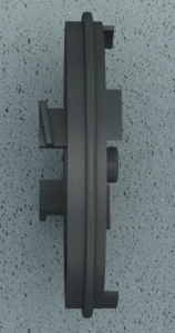
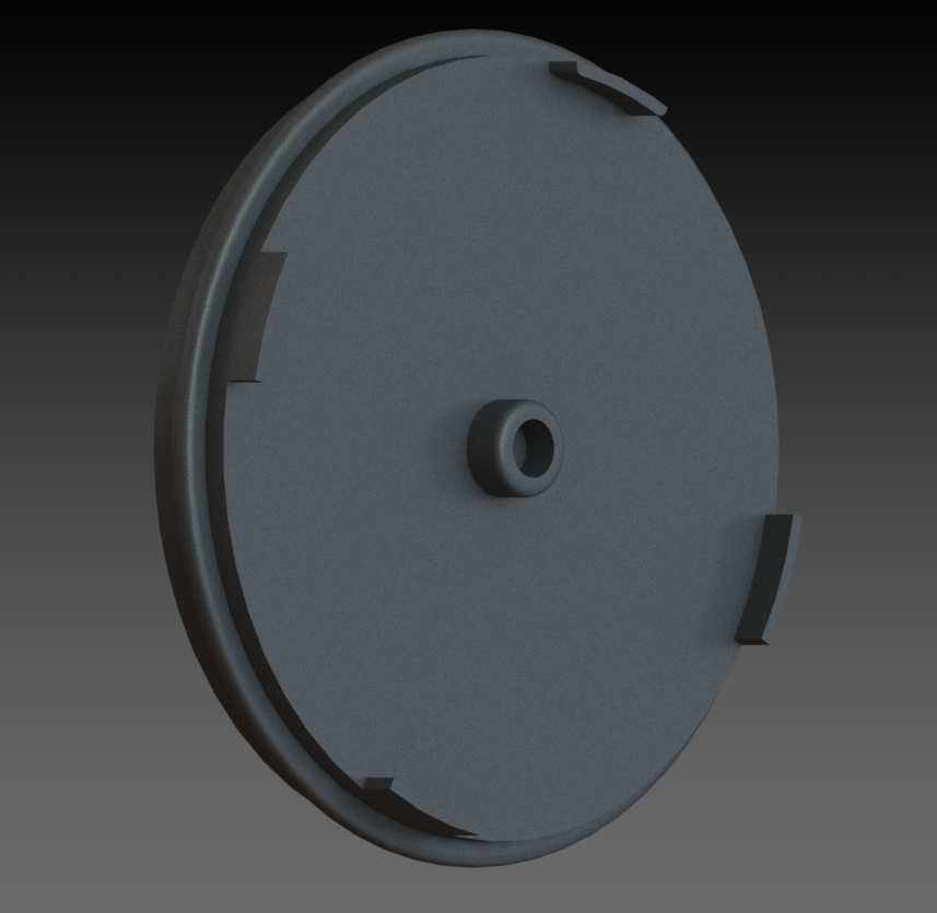
The shaft press fit design on the back of the connectors was to allow for full rotation of the connectors, without having to use any sort of adhesive that would permanently bind the motors to the connectors which is extremely crucial as we rapidly prototype. The difficulty of making a shaft for the micro planetary motors, stems from the unique star shaped shaft design, which proves to be difficult to obtain a usable grip on. As 3D printers are unable to replicate the star shaped design as such small sizes, it was impossible to create a shaft press fit design that perfectly grasps onto the shaft, unlike a d-shaft.
Photo Interrupters Implementation
The image below shows the back of the connector with the implementation of the tabs for the photo-interrupters. As discussed earlier, this is necessary because when the tab interrupts the beam given off by the photo-interrupter the connector stops rotating. Also, it can be seen that the outer ridges of the connector are indented outward to fit in to inner ring of the sleeve that’s in the cubic module.
Conclusion
The main issues that we needed to create a solution for with the modules, were the motor mounts, and subsequently the sleeve design. The motor mounts are not ideal, as they rely solely on the reliability of the press fit measurements, which does not ensure a solid grasp on the motors themselves, especially due to the flexible nature of ABS plastic and ONYX. However this issue was solved with the idea of a sleeve, which ensures that the connectors themselves have no load on the motor, and ensures that neither the motor nor the connector will fall out of place. And although it can be argued that the press fit designs for the joint motors on Limbi, the slide top on the module, and the modular contacts, do not fall out of place regardless of the amount of movement placed on them, the sleeve design was necessary to ensure that it wouldn’t even be a possibility. Due to the limitations of 3D printing and the fact that we only have 16 weeks to work on the project, it was difficult to come up with a viable solution for the sleeve. Eventually after meeting with Jeff, we realized that the sleeve would need to be removable, as we would need for the connector to be protected from falling out through both the front and back. If the sleeve was permanent, it would make it impossible to insert the connector into the sleeve in the first place. Ultimately, our design resulted in a snap fit removable sleeve with an indentation in it that is meant to hold the outer ring of the final design connector. once the connector is in place within the sleeve, the sleeve is then snapped into place on the module and the connector is fully enclosed in back and in front, which solved both the problem of the motors the connectors from sliding out, while taking the load off the motors.

