Limbi Generation 2
Author/s:
Alondra Vivas
Edward Villanueva
Colin Rogers
Table of Contents
Executive Summary
Currently, it takes astronauts approximately 8 hours to go on a space walk per day. While on the space walk, it takes a long time for them accomplish tasks due to the zero gravity and precision required. Being in space also adds to the risk factor for the astronauts. A solution to this problem is Limbi- which would help to create structure autonomously in space that would reduce the time, risk, and cost of building the structures autonomously. The purpose of this blog post is to detail how Limbi works.
Program and Project Objectives
Program Objectives
We continued the advancement of NASA JPL’s Limbi and Limbi Generation #1, a rectangular truss designed multi-jointed robot that allows for the connection of two modules through their docking mechanism. Limbi contains an androgynous connector on each end of its outer limbs. The cubic modules contain 4 faces where the exact androgynous connectors placed on Limbi also lay on the modules. The androgynous connectors will be lined up with one another and then rotated to create a seal during the docking process. Photo-interrupters are utilized to allow exact angles to be placed on the connectors for docking purposes. Power is transferred from Limbi to the cubic modules.
Project Objectives
Utilizing the idea of Legos, the cubic modules can be used to build structures autonomously in space. This would be accomplished by having Limbi hold on to a stationary module that act as an unmoving object in space, Limbi then picks up one cubic module with its connector, attaches it to another cubic module while remaining attached to the second cubic module, the next step would be to pick up another cubic module and repeat the process over again. Using the ArxRobot APP, the user can use the custom commands to allow for a motor angle sequence to play, whenever a button is pressed.
Mission Profile
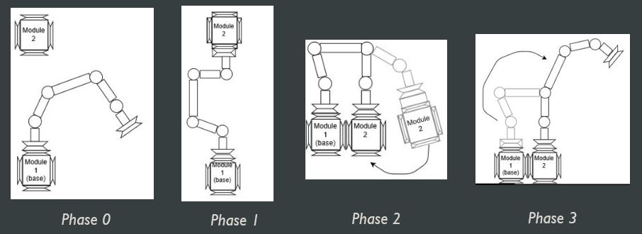
Limbi contains 3 separate phases. Phase 0 is Limbi attaching to a stationary module that acts like an unmoved mass in space while one of its limbs is detached from anything. Phase 1 is the limb that was free attaches itself to a module. Phase 2 is the furthest limb attaching the moving module to the stationary module. Phase 3 is that limb that brought the modules together releases its grasp from the module to repeat the process all over again. A visual description is shown in figure 1.
Limbi is composed of 4 joints, named joint 1-4. It also contains 2 identical sides called “side 1” and “side 2.” A visual description is shown in figure 2.
- Figure #1: Limbi Generation #1 Summary Blog Post
- Figure #2: NASA JPL Limbi
Project Features
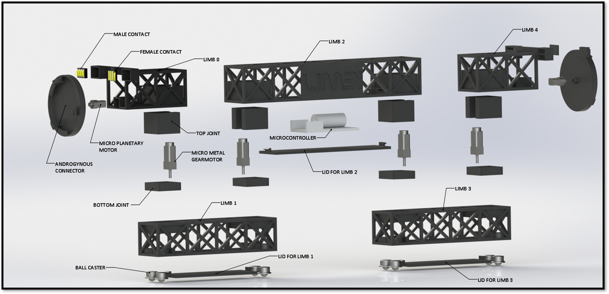
The detailed design portion of Limbi is shown below. In this image, the exploded view can be seen as well as the annotated view that names every component within Limbi.
- Limbi consists of 4 micro metal gear motors placed at each joint; they are placed within the joints via press fit.
- There are 4 ball casters on the bottom of limb 1 and 3 which are placed there also through press fit.
- A lid has been designed to go under limbs 1, 2, and 3 to access the electrical components within Limbi quicker.
- The PCB is placed inside limb 2.
- Power transfer contacts were added to the top outer edges of limbs 0 and 4 so that when the connector comes in contact with the module’s connector power can flow from Limbi to the modules.
- The micro planetary motors and press fit on a motor mount within limbs 0 and 4. They control the rotation of the androgynous connectors.
- The androgynous connectors of Limbi are on the outer limbs. The motor’s shaft is press fit in to the motor to make it rotate.
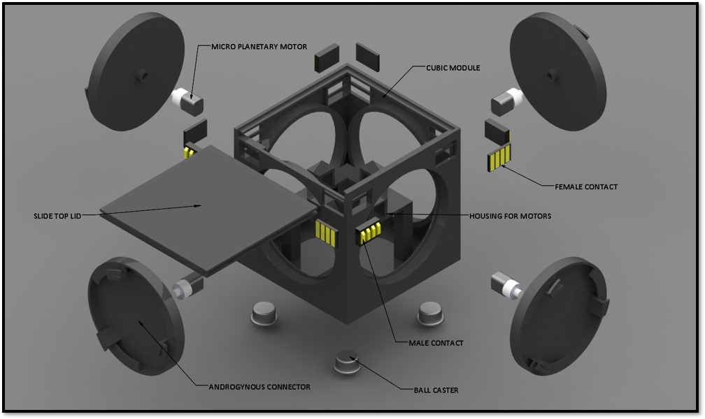
The detailed design portion of the cubic modules is shown below. In this image, the exploded view can be seen as well as the annotated view that names every component within the modules.
- The modules consist of 4 micro planetary motors placed at motor mounts.
- The shaft is in the back of the connector to allow them to rotate via press fit.
- There are 4 ball casters on the bottom of the modules on each corner which are placed there also through press fit.
- A lid has been designed to go on the top face of the cubic modules to access the electrical components within.
- The PCB is in the middle of the module.
- Power transfer contacts were added to the top outer corners of the module so allow power transfer to occur between Limbi and the modules.
Requirements
Engineering Standards and Constraints
C. 1. The Limbi will employ a custom PCB to extend the functions of the Arduino Nano and the 3Dot by allowing control of 4 micro metal gearmotors, 2 micro planetary motors, 2 electromagnets, and Arduino Nano communication.
C.2. Disassemble and Reassemble of the limbi and modules shall be constrained to less than 20 minutes (10 minutes+10 minutes).
C.3. The Limbi shall be completed by the date of the final: December 17th, 2019. C.4. The robot shall be designed in such a way that there are no dangling or exposed wires.
C.5. Manufacturability of 3D printed robots will minimize the number of files to be printed when using the library’s Innovation Space to print the final robot.
C.6. All Lithium (Li-ion, Li-polymer) batteries will be stored, when not in use, in a fire and explosion proof battery bag.
C.7. Software will be written in the Arduino De facto Standard scripting language and/or using the GCC C++ programming language, which is implements the ISO C++ standard (ISO/IEC 14882:1998) published in 1998, and the 2011 and 2014 revisions.
Program Level 1 Requirements
The Level 1 requirements for Limbi Generation #2 stemmed from the level 1 requirements created by Limbi Generation #1. These requirements were created for the conceptual success of this project taking place in space. This, in turn, led to the majority of the requirements being related to the mechanical and electronic design of Limbi.
L.1.1. Shall implement a low friction surface to simulate the environment in space.
L.1.2. Will make Limbi Shorter than the JPL Limbi for storage and rapid prototyping purposes.
L.1.3. Shall move each of the arm’s 4 joints according to their attached limbs, with 4 of the 5 limbs moving in total and the final limb acting as a stabilizer.
L.1.4. Will have each joint contain at least 270 degrees of motion in one plane (x-y) with a slew rate of tbd
L.1.5. Shall have the arm connect and disconnect with the cubic modules.
L.1.6. Shall include a docking mechanism to keep the arm and module connected as the arm moves until it is meant to be disengaged.
L.1.7. Shall have the arm contain a docking mechanism on each end to connect to two modules at once.
L.1.8. Shall have the arm be able to move the module in one plane (x-y).
L.1.9. Shall have the arm be able to lock two modules together through a mechanical design.
L.1.10. Shall be able to control the movement of the arm by the user with custom software.
L.1.11. Shall have Limbi controlled with a micro controller (3dot).
L.1.12. Shall have each cubic module be capable of providing power to the arm (Waived).
L.1.13. Should have Limbi and the cubic modules be powered by a single rechargeable battery per module/Limbi.
L.1.14. Will have docks on 4 of the faces of the cubic modules for demonstration purposes.
L.1.15. Shall have the module indicate when a secure connection is made between the Limbi and modules with an LED.
L.1.16. Shall have one module as the base module and shall be stationary to represent a large unmoving mass in space.
System/Subsystem/Specifications Level 2 Requirements
The Level 2 requirements of Limbi Generation #2 stem from the Level 1 requirements. During the final demo, these were the requirements presented for verification.
L.2.1. Limbi will be supported with 8 small nylon metallic ball casters (each weighing 5.0g) on Limb 1 and Limb 3 to simulate the conditions where the arm will not be affected by gravity.
L.2.2. Limbi will follow the form factor of the JPL version; the lengths will be optimized in respect to inverse kinematics.
L.2.3.1. Each joint shall control 2 limbs at a time.
L.2.3.2. Joints will be tested to prove they can control their attached and extended limbs.
L.2.4.1. Limbi will have 4 joints controlled by micro metal gearmotors.
L.2.4.2. Each micro metal gearmotor shall require no more than 170 mA at 7.4V as defined in power study.
L.2.5.1. The docking mechanism shall consist of the mechanical androgynous connector to allow Limbi to successfully attach from the module.
L.2.5.2. The docking mechanism shall consist of the mechanical androgynous connector described, to allow Limbi to successfully detach from the module.
L.2.6. Only 1 docking DC motor shall be in motion at once, so the module does not undock while the other module docks.
L.2.7. The docking mechanisms on each end will be identical to each other.
L.2.8. The micro metal gearmotors shall be able to provide more than 2.5 kg. cm based on the force to move the coupled assembly object in a planar field.
L.2.9. The connectors shall be able to come together and create a solid seal without the use of electricity.
L.2.10.1. The user interface shall utilize wireless Bluetooth to control Limbi.
L.2.10.2. The custom software will be implemented through the Arxterra App.
L.2.10.3. The user interface shall have push buttons/toggles for pre-determined movements.
L.2.11. The project will use a 3dot board mounted within the Limbi arm to allow the 4 micro metal geared motors and 2 micro planetary motors to be controlled directly by the microcontroller.
L.2.12. The power provided from the module will come from a battery (7.4) via the docking mechanism.
L.2.13.1. The battery for Limbi will be capable of providing 1055 mA current (if needed).
L.2.13.2. The battery will have a capacity of 1500mAh, provides 7.4V output, and has a discharge rate of 45C with a width of 35mm to allow for storage within limb 2.
L.2.14.1. The module will have an androgynous connector on all 4 faces.
L.2.14.2. 4 faces on the cubic module will serve for both interconnections among each other and to connect to Limbi.
L.2.15.1. The LED on the module shall be activated by one of the four power connections.
L.2.15.2. The LED will be on the corner so the person controlling the app can easily see that a secure connection has been made.
L.2.16. The arm will always be attached to a module.
Allocated Requirements / System Resource Reports
The power allocation came from a combination of estimating the expected current at max power drawn when every motor is active and the micro controllers outputting max current from all their pin outputs. With this we can see that in a worst case scenario the entirety of Limbi and the modules would take approximately 1 amp. However, since we only use either 1 micro metal or micro planetary motor at any given time, and only use 1 or 2 pins on the 3dot / nano for current draw, this reduces our expected current drastically. This gives us an expected current draw of only 200mA versus the max of 1 Amp. The contingency we obtained was based off the max expected plus our selected margins, to allow for about 220mA of current running through both Limbi and the modules, at any given time. Our actual measured current was even smaller, with the majority of the resources using below the expected, this allowed for us to make a low power consumption version of Limbi, that would last several hours from a single Li-Po battery.
| Power Allocation | ||||
| Resource (individual) | Expected Current (mA) | Measured Current (mA) | Uncertainty % | Margin (mA) |
| Micro Planetary Gear Motor | 20 | 10 | 10% | ± 2 |
| Micro Metal Gear Motor | 70 | 67 | 10% | ± 7 |
| 3 Dot | 40 | 20 | 10% | ± 4 |
| Photo Inturrupter | 2.5 | 3 | 10% | ± .25 |
| Arduino Nano | 40 | 20 | 10% | ± 4 |
| Red Led | 20 | 22 | 10% | ± 2 |
| Hall Encoder | 2.5 | 2.2 | 10% | ± .25 |
| Resource (Max consumption/ worst case) | Expected Current (mA) |
| Micro Planetary Gear Motor (4) | 80 |
| Micro Metal Gear Motor (6) | 420 |
| 3 Dot (1) | 200 |
| Photo Inturrupter (4) | 10 |
| Arduino Nano (1) | 200 |
| Red Led (1) | 20 |
| Hall Encoder (4) | 10 |
| Power Allocation | 1000 |
| Total Margin (mA) | 19.5 |
| Total Actual (mA) | 144.2 |
| Total Expected (mA) | 200 |
| Total Max Consumption / Worst Case (mA) | 940 |
| Contingency (mA) | 219.5 |
The Mass allocation was a result from an estimate of the weight of Limbi Generation #2 and the cubic modules which were found by using the volumes that were given to us in the innovation space center as the files were submitted. From here we took these volumes and multiplied them by the given weight per cubic centimeter of the material we were using to gain an accurate estimate of the total weight. Initially, we visualized using electromagnets and an additional cube which would have added to the final weight analysis. Because we used ONYX for the material of Limbi’s limbs, and for parts of the modules, we found the overall weight of these parts to be dramatically decreased in comparison to that of the JPL version which used various metals such as aluminium for its limbs. Our contingency allows for us to have slight variations on mostly the purchased parts, as the data sheets for these parts may be inaccurate when weighing, as well as any slight errors on the prints which may have added or weight unexpectedly.
| Mass Report | ||||
| Resource | Expected (g) | Measured (g) | Uncertainty | Margin |
| Limbs 0 & 4 | 90 | 78 | 15% | 13.5 |
| Limbs 1 & 3 | 120 | 106 | 10% | 12 |
| Limb 2 | 100 | 86 | 10% | 10 |
| Top Joint (4) | 40 | 32 | 10% | 4 |
| Bottom Joint (4) | 32 | 24 | 10% | 3.2 |
| Micro planetary motor (8) | 56 | 64 | 5% | 2.8 |
| Micro Metal gearmotor (6) | 96 | 72 | 5% | 4.8 |
| Ball Casters (16) | 64 | 80 | 10% | 6.4 |
| Cube ABS (2) | 100 | 108 | 10% | 10 |
| Slide fit Onyx (2) | 30 | 42 | 5% | .6 |
| Androgynous connectors (10) | 150 | 100 | 5% | 7.5 |
| Modular Contacts (20) | 5 | 5 | 5% | .25 |
| Arduino Nano (2) | 14 | 14 | 15% | 2.1 |
| 3 Dot | 15 | 17 | 5% | .75 |
| Total Expected | 912 |
| Total Measured | 828 |
| Total Margins | 61.25 |
| Project allocation | 1000 |
| Contingency | 26.75 |
The size of Limbi is an important feature that needed to be tracked, as we planned on reducing the size of Limbi by more than 50% of the JPL version, early on into the creation of Limbi. Therefore, we ensured that every limb was created according to the form factor that JPL had investigated early on, which allows for the docking of two modules. With these provided ratios, we were able to create a smaller version of Limbi, while containing almost the exact same form factor of the original. We found that we were able to reduce the size of Limbi and the cubic modules, by about 56% of the original size, which was close to our goal of 60% and surpassed our requirement of 50%
| Size report | ||||
| Resource | Expected (mm) | Measured (mm) | Uncertainty | Margin (± units) |
| Limbs 0 & 4 | 80 x 35 x 35 | 77 x 43 x 38 | 10% | 12 x 5.3 x 5.3 |
| Limbs 1 & 3 | 150 x 35 x 35 | 151 x 43 x 38 | 10% | 15 x 3.5 x 3.5 |
| Limb 2 | 250 x 35 x 35 | 250 x 43 x 38 | 10% | 25 x 3.5 x 3.5 |
| Androgynous Connectors (2) | 12.5 x 60 x 60 | 12.5 x 60 x 60 | 5% | .63 x .3 x .3 |
| Cube | 90 x 90 x 90 | 90 x 90 x 90 | 5% | 4.5 x 4.5 x 4.5 |
| Total Expected (mm) | 640 x 265 x 207.5 |
| Total Measured (mm) | 638 x 289 x 216.5 |
| Contingency (mm) | 1278 x 554 x 424 |
Project Report
Project WBS and PBS
WBS:
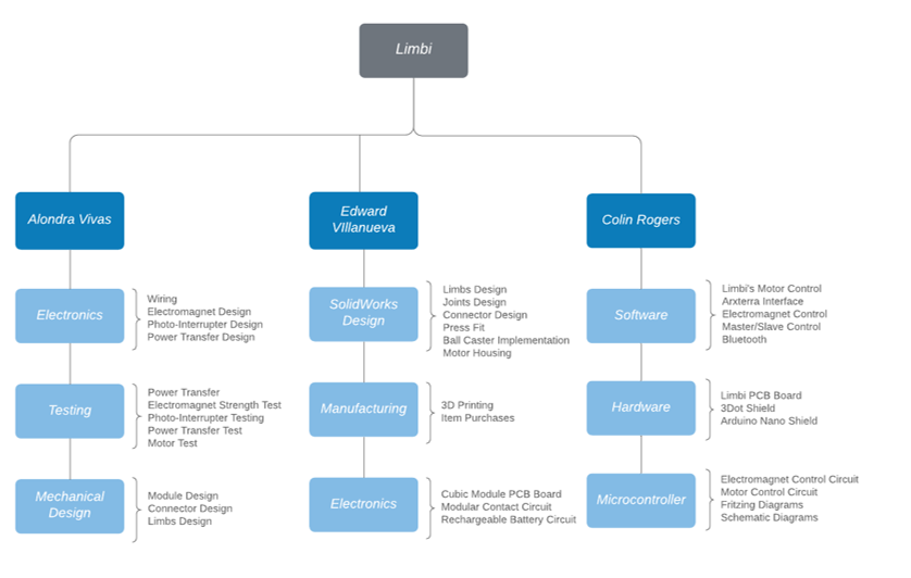
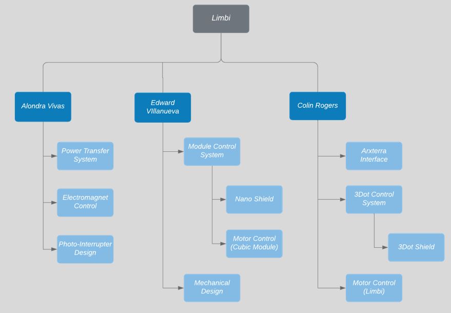
Limbi’s Work Breakdown Structure is divided into Limbi’s three different members, from here we break down the main categories in which they are taking control of, with 3 categories being assigned to each member. These tasks include, Electronics, Software, Mechanical Design, Manufacturing, and so on. The larger categories such as Electronics, have overlap between members, where more than one individual at a time ca be working on electronics, or a subcategory of the electronics such as the Hardware. From there, specific tasks are assigned within the categories, where some tasks may overlap between members. In our case, there was an overlap between two members in which they were both assigned to do the design of the limbs, what this means is that these two members will collaborate on this specific task.
PBS:
Limbi’s Project Breakdown Structure is once again divided into its three members, from here each member is given a design task that are essential to ensure Limbi is fully functional. For example, one member received the assigned task of the “3Dot control System”, which encases a broad amount of sub tasks including the shield for the 3Dot and the programming required to get the 3Dot to function.
Cost
For the cost of limbi, we allocated an inital $750 dollars to the project, this was mostly based of the cost of the higher priced items such as the 3 dot, the ONYX material, and the motors themselves. Knowing that we would have many rapid prototypes and that many of them would be created in ONYX, we had initially allocated around 80 dollars for the 3D printing, the motors cost approximately $100, and since we initially believed we would be using multiple 3Dots we had already reached a price point of about 450 dollars just on those 3 components alone. On top of this we still needed additional components such as the ball casters, modular contacts, and batteries which we knew would cost us additional finances. This is why we added an additional $300 to our final allocation. However, we soon realized that we would not be using multiple 3Dots, and this brought our cost down dramatically so that we resulted in spending approximately $250 dollars less than our initial assumption.
| Cost Report | |||||||
| Resource | Unit Price | Expected Cost | Extra Charges | Quantity | Uncertainty | Margin | Actual Total Cost |
| Calculations | Per Item | (Unit Price) * Quantity+ Delivery Fee+Tax | Delivery Fee + Tax | Amount | Estimate | Uncertainty*Expected Cost | Expected Cost + Extra Charges |
| Micro Metal Geared motor w/Encoder (6V, 41RPM, 380:1) | $11.9 | – | $15.00 + $7.14 = $22.14 | 6 | – | – | $93.54 |
| Ball Casters | $10.99 | – | – | 3 | – | – | $32.97 |
| Onyx filiment for 3D printer Purchased | – | – | – | – | – | – | $84.86 |
| Abs filiment for 3D printer Purchased | – | – | – | – | – | – | $47.46 |
| Arduino Nano Every | $11.90 | – | $8.12 shipping | 3 | – | – | $51.94 |
| 3dot | $80 | – | $6.20 tax | 1 | – | – | $86.2 |
| Micro planetary motor x5 | $11.99 | – | – | 3 | – | – | $35.97 |
| Modular Contacts | $4 | – | $1.50 tax | 10 | – | – | $41.5 |
| Photointurrupter x10 | $8.88 | – | – | 1 | – | – | $8.88 |
| 7.4V 1500mAh Battery Pack | $11.99 | – | $1.12 tax | 1 | – | – | $13.11 |
| Adafruit Dual H-Bridge Motor Driver | $5.96 | – | – | 5 | – | – | $29.8 |
| DC 3V 5RPM Micro Speed Reduction Motor | $10..68 | – | – | 2 | – | – | $21.36 |
| HM-11 | $8.99 | – | $0.92 tax | 2 | – | – | $19.92 |
| Total Expected Cost | $0.00 |
| Total Actual Cost | $520.05 |
| Total Overall Cost | $520.05 |
| Contingency | $520.05 |
Schedule
Burndown and/or Percent Complete
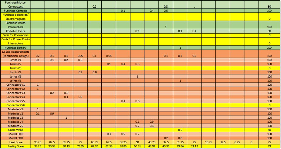
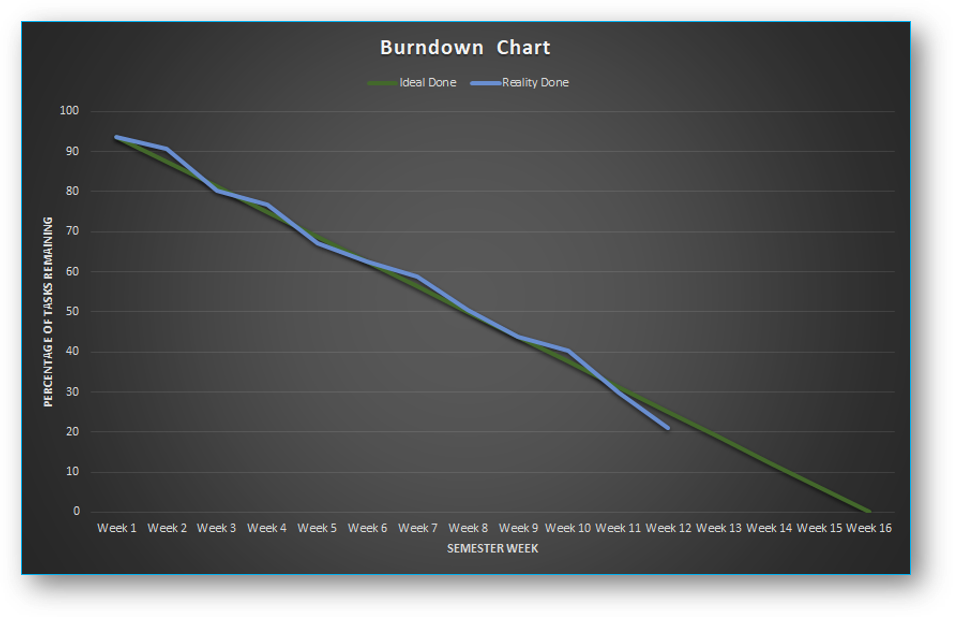
Our burndown chart is from the CDR, however you can see that at this point, the group was at 79% of completion. The only things the group had left to do from this point were:
Final Documentation- Master Control Software
- Slave Control Software
- Photo-Interrupter Code
- Photo-Interrupter Test
Solenoid TestFinalized Purchases- Code for the Motors at the Connectors
- Code for the Photo-Interrupters
Limbi V3Connectors V6Cable Wrap
As you can see from above, we did not get to many of the software aspects of Limbi before the final demo, which unfortunately left the modules incomplete, however Limbi itself, reached full completion.
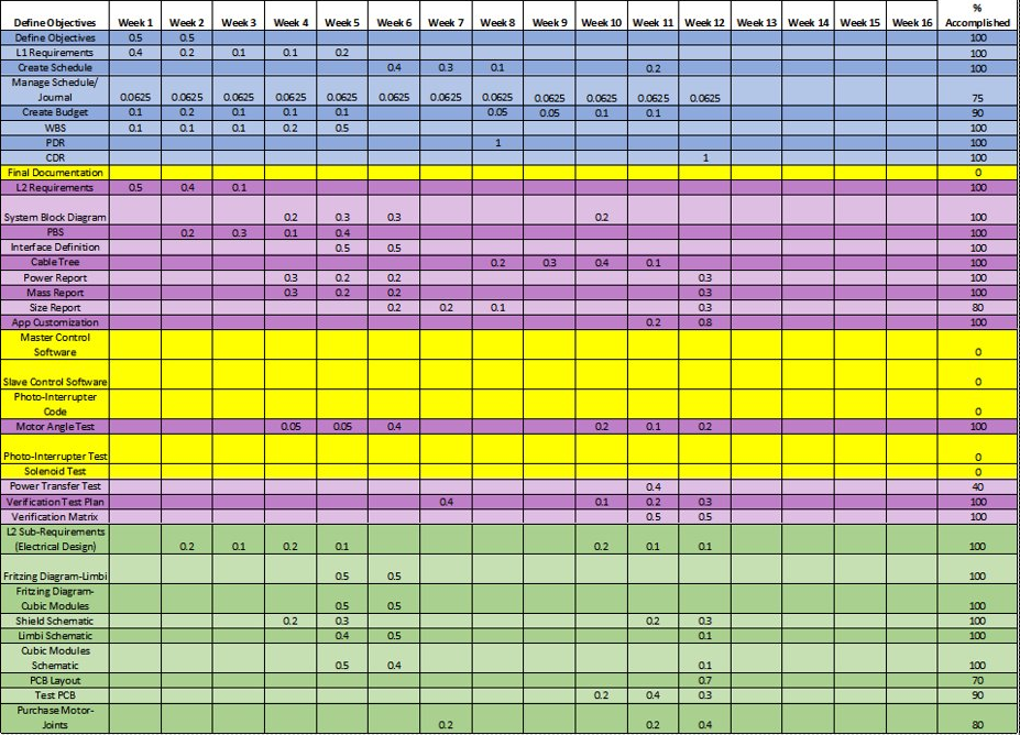
Figure 8 shows the burndown chart that helped create the burndown graph. It details all the work done from week 1 up until week 16. The chart is split into 4 separate sections where the blue section is work for the project manager such any documentation required, the purple section is for the purchases and testing, the green section is for electronics, and lastly the orange section is for the mechanical design of the project. Some items take several weeks to complete, therefore, the % accomplished column has the percentage completed of that row’s task.
Concept and Preliminary Design
This section highlights the resources used to get an idea of how Limbi should be designed. It shows the process in which we came to create our initial designs and what caused us to choose specific design paths. It shows the research previous groups have conducted and how we used that research as well as their trial and error to create our own product and improve upon their faults.
Literature Review
For our project, we had 4 main pieces of documentation to help us push forward the design of Limbi. These resources were: JPL’s IEEE article, titled “An Untethered Mobile Limb for In Space Assembly” which highlights all the testing and research that was done by JPL on their initial run through of Limbi. The article proposed their mission objective of developing autonomous robots that would replace astronauts when doing in space repair, as well as having the ability to construct large structures in space, autonomously. Their biggest issues that they encountered were the docking mechanism, which was meant to be fully androgynous, and that the current issue with the docking mechanism, was that it required constant power to operate properly as it used electromagnets to keep the modules together, as well as Limbi connected to the modules. This means that constant power would need to flow between modules and limbi, in order for the docking to keep. In addition, the electromagnet strength drops rapidly withing small distances from one another, making the mechanism useless.
The next documentation was the previous Arxterra PDR document as well as their Arxterra document for research, which was essentially a project proposal for the Limbi project to be a full 2 semester long project that was to be a collaboration between MAE, CECS and the EE departments. This PDR and document highlighted key points within the IEEE article and went into detail about the difficulties that JPL had during their initial run of Limbi, as well as proposing solutions to these issues for future generations to attempt. The paper made a point to highlight the goals of Limbi as well as defining some key points in the design of Limbi and the modules that proved to be the failure of JPL’s version.
In addition to this, the previous semester’s Final blog post, also gave us a huge insight in what will work for Limbi, and what will not. The biggest problem being that they created their Limbi, so that all limbs are on the same plane as one another, this creates an issue in which limbi must then be elevated at all times, so that it can align itself with the cubic modules, for proper docking. Although this would not be an issue in space, it became a issue for the previous generation, as they could not move Limbi without it falling over due to the large ball casters required to elevate it to and equal plane as the modules. In addition, the biggest forewarning of the previous generation, was to not use servo motors, which we assured we did not, as they had found difficulty getting Limbi to properly stop the servos at the correct moment, or to keep the rigidity of Limbi, constant throughout as the motors moved it.
With the information gathered through these documents, we were able to lean towards an approach of our Limbi, closer resembling that of JPL’s verision, while straying away from the electromagnets, which were not a favorable design decision. In addition, we learned that we needed to create an actual androgynous connector, with a mechanical seal, something that last semester lacked as well, as the connectors on the ends of Limbi, did not match the connectors on the modules. In addition, module to module connection was done purely through magnets in the corners of the modules, which did not enable enough rigidity, as warned by the spring 2018 research paper.
Design Innovation
-
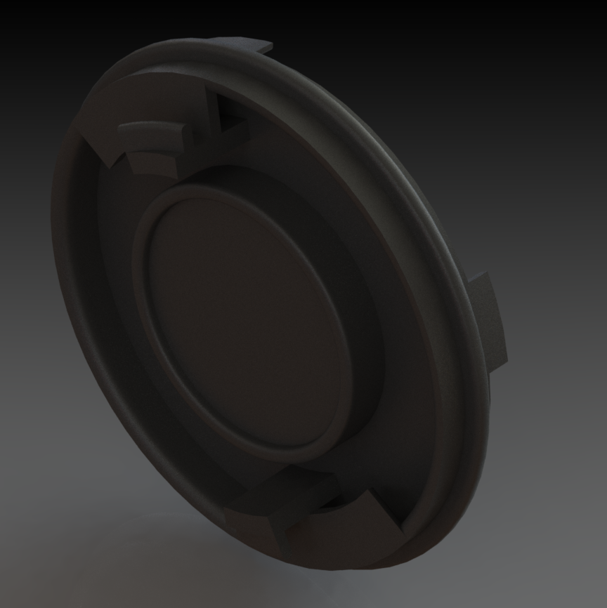
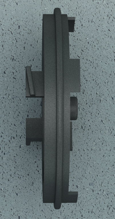
- Androgynous connector – A connector that has the ability to connect with any of its same kind. Is used for both arm to module docking, as well as module to module docking and arm to arm docking as well. This design was based off a combination of a fire hose, and bottle cap thread idea, while also attempting to use some of NASA’s International docking standards, to reach momentum less docking while in a low friction environment.
This design allowed for a metal plate in the middle of the connector, which would allow for a magnet placed on the end of the Limbi connector, to align the two connectors, finally Limbi would rotate to lock the two connectors into place, via the threads that are located within the connectors themselves. The backside of the design also included flags that were to be used with photo interrupter , this would allow for the connectors to rotate about 90 degrees before the photo interrupter would be engaged and would turn off the rotation of the connector.
- Modular Contact Power transfer – The modular contacts located on both the end of limbs 0 and 4 on Limbi, in addition to every face of the cubic modules. Allowed for power transfer between both the modules and Limbi itself, with Limbi being the main source of power for these modules. The contacts have both a male and female version, that transfer power when the two contacts meet and touch one another. This allows for power transfer and eventually data transmission through the contacts, so that the micro controller within Limbi, could tell the micro controller within the modules which face to spin, at the proper time
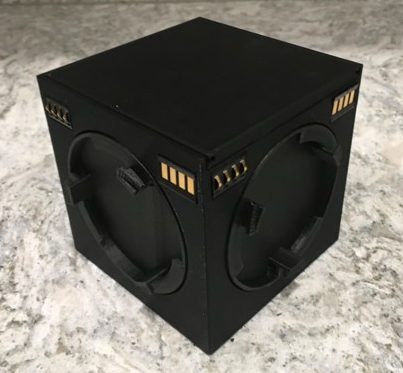
Figure 11. This image shows the modular contacts in the upper right and left hand corners of the cubic modules
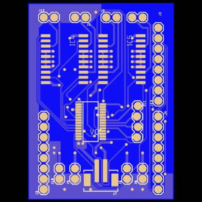
3. Limbi Motor control PCB – The PCB we designed for the 3Dot was designed to allow for full motor control of 6 motors, 4 of which had hall effect sensors attached, so that we could input specific angles to control Limbi. This design made use of I2Cs and H bridge Chips, to enable the wiring of all 6 motors within Limbi, to be controlled through the 3Dot, and powered by a 7.4 V Li-Po battery. The board is compact at only 48mm long and 35mm wide, as it connects on the top of the 3Dot board.
- Androgynous connector – A connector that has the ability to connect with any of its same kind. Is used for both arm to module docking, as well as module to module docking and arm to arm docking as well. This design was based off a combination of a fire hose, and bottle cap thread idea, while also attempting to use some of NASA’s International docking standards, to reach momentum less docking while in a low friction environment.
Conceptual Design / Proposed Solution
The Limbi team came up with a design for androgynous docking that utilized the idea of a fire hose, in conjunction with a bottle cap. This idea was created on the issue of needing a mechanical interlocking docking mechanism that was also androgynous. In addition a key issue we say with last semester’s Limbi was its elevated state on the large ball casters that were attached to the bottom of Limbi. With these constraints on our design, we soon realized some key points that would effect the entirety of Limbi and the modules as well. The key points were as follows:
- The androgynous connector must be made circular, to allow for any angle of docking to occur
- The connectors must be made so that they dock softly, and that minimal motion is required once the soft dock has been engaged, so that they can create a permanent seal without exerting excessive force on the modules, causing them to go astray in space.
- The modules themselves had to have some sort of intelligence, so that they could know or be told, when to rotate their faces, to dock with the next module
- Limbi must be made in a form factor that represents JPL’s Limbi, as they did not have an issue with ball casters despite using 16 of them on their version of Limbi.
With this in mind, the end result of our Limbi, was to have limbs 1 and 3 lie beneath the others both for stability purposes and to allow the end limbs to line up correctly with the module. Although not ideal, we also realized we needed a low level of intelligence within the cubes, so that they could rotate their connectors when need be. This would be done utilizing a simple micro controller to micro controller communication, where the 3Dot was the master, and the Nano was the slave. The actual data transmission would occur through modular contacts in the corners of both the cubes and the corners of the limbs 0 and 4. Finally, the connector would require us to have a sort of mechanical lock, which would require no power and minimal movement to engage and disengage. The end results of these conceptual designs can be found in the images below.
System Design / Final Design and Results
The Following section represents the System Block Diagram, Interface, and wiring diagram as of the CDR. Although nothing has changed for the interface, the most notable changes come from the Block Diagram and the wiring diagram, as wiring Limbi through PTFE tubing, proved to be difficult.
For the block diagram the most notable changes are:
- Electromagnets are no longer implemented within the modules or Limbi, and instead were replaced with ceramic magnets for Limbi and steel striker plates for the modules.
- The power transfer is no longer from Module to Limbi, but rather Limbi to Module, this is a decision based on the fact that we wanted Limbi to be the only smart component within the project.
For the Wiring diagram, the most notable change was the fact that we could not group the wiring as we wanted, and instead took 3 tubes rather than the intended 2, to hide the wiring within limbs 1 and 3. This was because it was difficult to find tubing large enough for all the wires we needed to hide.
System Block Diagram
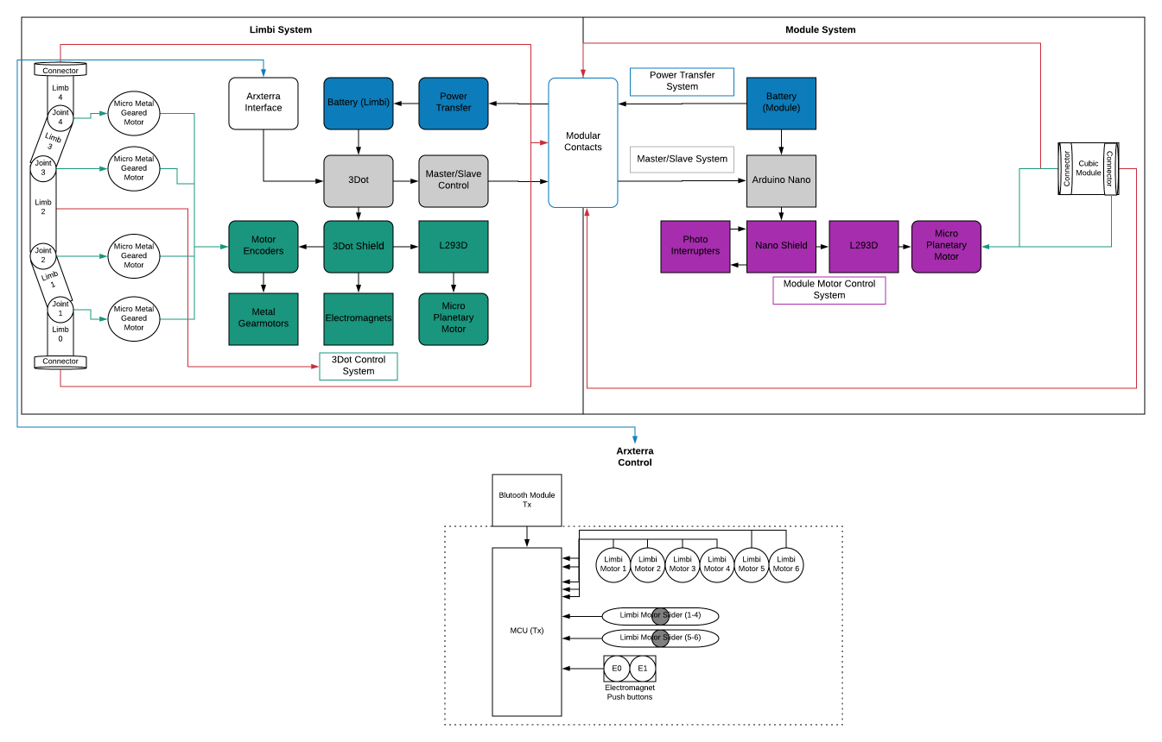
The system Block diagram we created, shows the various systems and subsystems within Limbi, and how they control the joints of Limbi, as well as the connectors within the modules, all through the ArxRobot app. The Power starts with the blue section, in which power is meant to be provided from the module, to Limbi’s battery, however this reversed in later iterations of Limbi. The grey portion is meant to be the Master/Slave communication between the 3Dot and the Nano. The green is the 3Dot Control system, and everything meant to be controlled by the 3Dot and Shield. On the module side, we can see that the pink is the Nano Control system, where everything is being controlled through the Nano, by the inputs given to the 3Dot, from the ArxRobot app. You can also see that the center of the block diagrams contains the modular contacts, this is because they are the heart of where all the power and data transfer occurs within the system. The Arxterra control can be seen at the bottom of the diagram, where the motor selection widgets and the angle selection widgets are on display.
Interface Definition
Interface Matrix
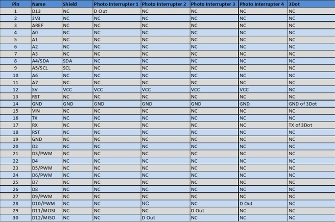
The following interface is designed to show the pinouts of the Arduino Nano Every, and how we planned on utilizing and implementing them within the logic of the modules.
Cable Tree
Below shows the truss design of limbi, which created a possibility for the wires within it to be easily routed, but difficult to hide. Our quick solution was to use heat shrink wrap, therefore, the wires exits the motors and we take it out to go outside the truss design followed by guiding the wires to connect within limb 2 where the PCB is placed. This solution did not work as the heat shrink wrap is too stiff and from an aesthetics perspective it didn’t look pleasing to the eye. Below is the cable tree we created to solve the solution of having the wires stay hidden within Limbi. As one can see, the GND and VCC wires coming from the connectors will have cable wrap when they intersect with the GND and VCC wires of the micro planetary motors. The micro metal geared motors’ wires also have cable wrap and will connect with the connector’s and the planetary motor’s cable wrap. The wires will go down joint, 1 and 4 through Limbi 1 & 3, and then back up joints 2 and 3. Cable wrap will then connect the geared motors’ wires to the other wires that went up the joints while being guided to the PCB. The actual cable wrap will be spaghetti wire insulation tubing which possesses the minimum coefficient of friction of any known solid by being made of Teflon. Unfortunately, the spaghetti wire tubing proved to come in sizes that were too small for the large amount of wires we needed to feed within the tubing itself, this made it very difficult to obtain any sort of wiring to travel trough the tubing. As a result we ended up using 3 separate strands of tubing as apposed to the intended 2. In addition, the tubing was placed only in limbs 1 and 3, as the wires were too short to appropriately hide within limbs 0 and 4, and limb 2 was the housing for the electronics which did not require tubing at all. But because of the truss design of Limbi, we were left with many exposed wires that could easily be seen, despite our best efforts to hide them.
Modeling/Experimental Results
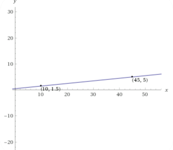
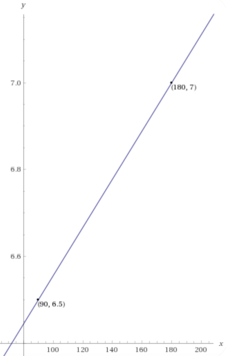
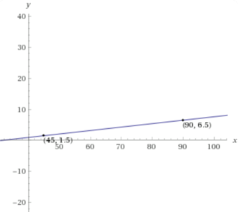
- Micro metal gear motor angle test
In order to get the Micro Geared Motor to turn to a specific angle a test of trial and error was performed. Points were plotted in order to derive the equations. The reason this had to be done was because we could not understand why the motors were not turning at the specific angle we gave it. As a quick solution we did these graphs to figure out what value to give the motor.
2. Power Transfer Test
To determine that the power transfer contacts were operational, a power transfer test was done. We accomplished this by soldering an LED to the back of one of the contacts of Limbi. We also soldered a wire to the back of one of the cubic modules’ contacts to then attach it to a power source. The conclusion was that since the LED turned on upon impact, the contacts are working properly, and the mechanical design implemented for the position of the contacts is successful.
3. Connector rotation Test and Limbi Control test
This test was conducted to see if we have full rotation control of the connectors at the end of Limbi, with this proven to be true, it allowed us to be able to dock Limbi. In addition this final test allowed us to see if we had full Bluetooth control of limbi’s joints.
Mission Command and Control
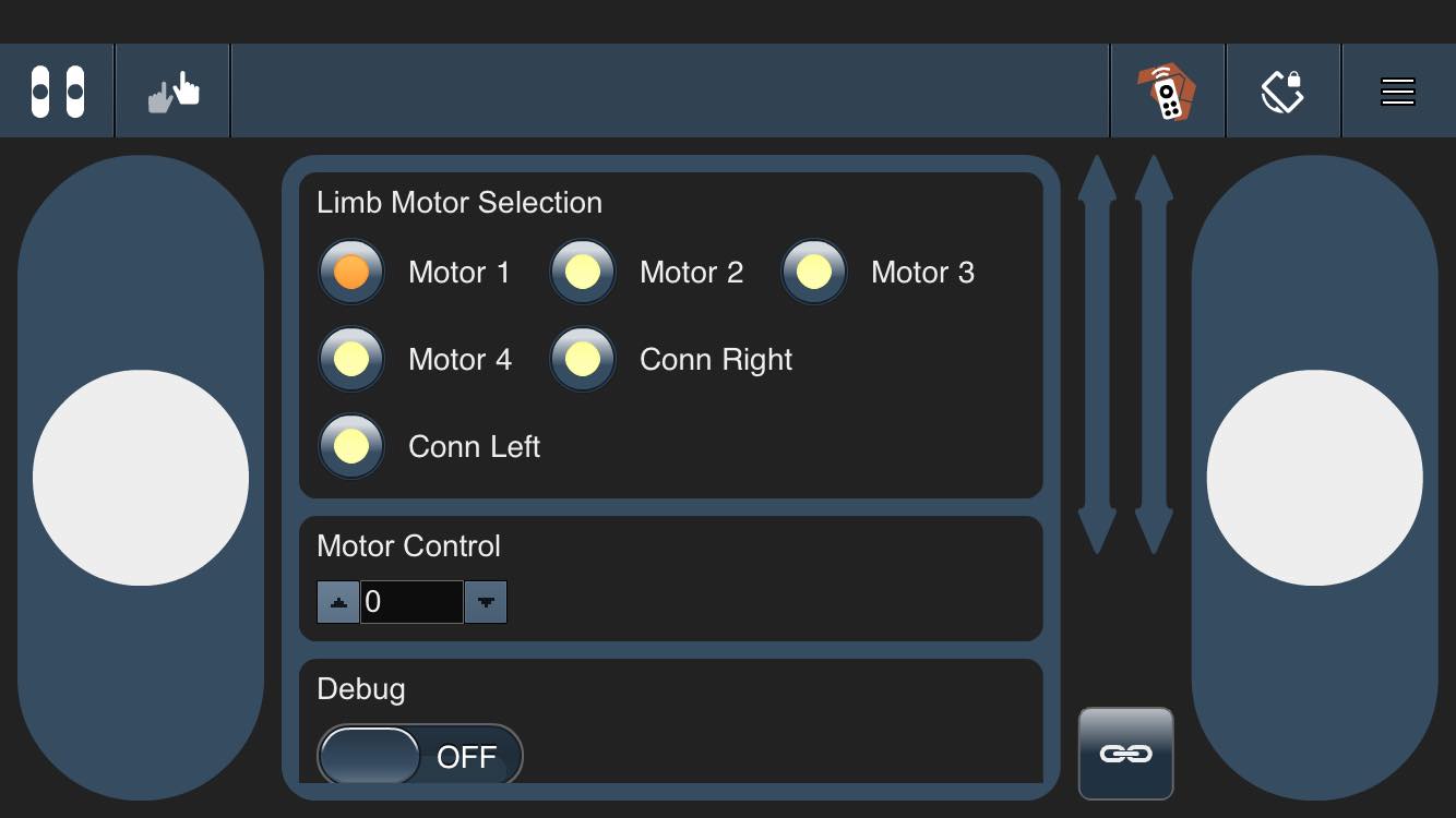
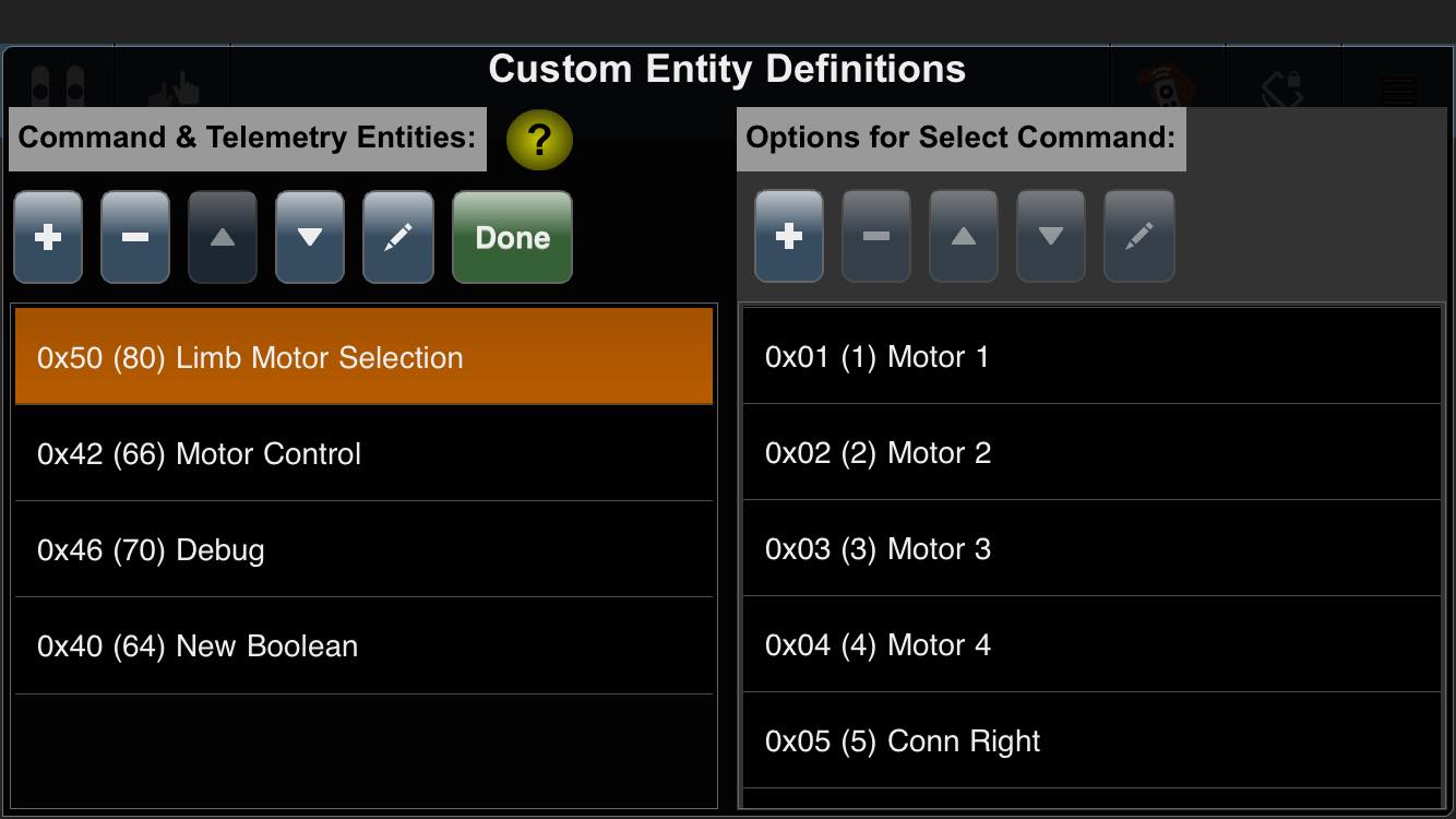
The above pictures show the custom commands that were created to control Limbi through the ArxRobot App. Below is a overview of those commands and their functions within the Code itself.
MOVE (0x01) – The move command is modified to utilize the tank slider controls as viewed above. They behave as push buttons in our case, as we hit the top of the tank slider when we want to rotate a selected motor in the clockwise direction, and hit the tank slider down when we want to rotate a selected motor in the counter clockwise direction. The reason for choosing the sliders versus the joystick, is that the sliders are only polled once, unlike the Dpad which is constantly looking for a change in direction.
Limb Motor Selection (0x50) – This command writes to a global variable named motor, which is used to select which motor we currently want to operate. It is a simple code that enables the selection of any one of our 6 motors, through radio buttons.
Motor Control (0x42) – This command is used to control the angle that we want to move Limbi. It uses a stepper as the slider switch is not accurate enough for our purposes. Once the angle is selected, it writes to a global variable named angle. From here the move command is used to decide which direction we want to rotate, given the specified angle.
Debug (0x46) – This command is a simple Boolean that is used to control the on board light on the 3Dot. its sole purpose is to let us know if we are still receiving and transmitting wireless communication with the app, or if something has been coded correctly.
Electronic Design
Our Electronic design consisted of two custom PCBs which were developed side by side, with one for the usage of controlling 6 motors, 4 hall effect sensors, as well as 2 electromagnets, all on the 3Dot. While the other was to control 4 motors and their basic left and right rotations using photo interrupters, on the Arduino Nano.
PCB Design
3Dot PCB
For our PCB, we decided that the 3Dot was a good choice of a board, as it already had two integrated H-Bridge chips to be used to control Motors. In addition, using this board would ensure ease of compatibility with the ArxRobot app, and it had built in Bluetooth, which meant we did not have to design a shield with space for the HM-11. The board we designed made use of the integrated H-Bridge chips on the 3Dot and just extended its capabilities to conform for the various motors we needed control of.
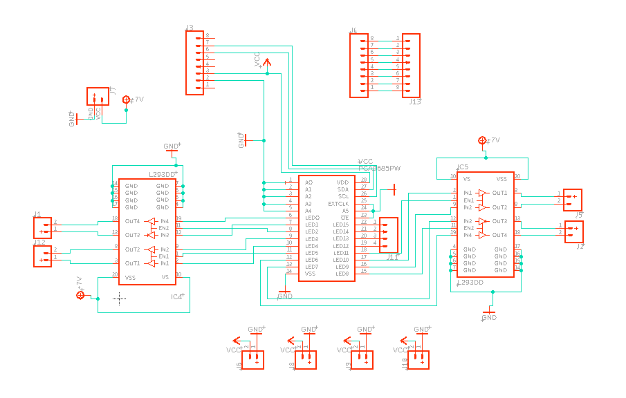
The schematic for the PCB board of the 3Dot Board can be found below, you can see that it utilizes I2C chip as well as multiple H bridge chips, and multiple headers. This is to allow for full control of the motors themselves as well as the hall encoders. The I2C used was the pca9685 chip which allows for the control of 16 separate pwm channels. Through this, Two entire H-Bridge chips can be controlled, which allows for the full control of four distinct motors. Limbi Generation #2 is using a micro gear motor in each of its 4 joints. These are the pwm channels that are used to control the H-Bridge motor control chips. The SCL and SDA pins allow for serial communication to the 3Dot.
Below is the V4 (final) design of the 3Dot shield. It was made slightly taller than than its previous iteration, in order to accommodate the new connectors for the encoders digital inputs. It’s 48 mm long and 35 mm wide which enable it to fit well within the 36mm wide enclosure of limb 2. This shield has thick power traces, better ground routing, and the star configuration for the power. This shield allowed for full motor control of all joints in Limbi as well as leaving room for 2 electromagnets that could be turned on or off by the shield.
Nano Every PCB
In addition to the PCB for our 3Dot, we also needed to construct a PCB for the Nanos we were using within the modules themselves. However, because the nano and 3Dot use the same architecture, we were able to create a board that was very similar to the 3Dot PCB, just utilizing a different pinout but still using the same H-Bridge chips, the l293DD. The PCB for the nano was not as complex either, requiring the control of just 4 motors, all without encoders.
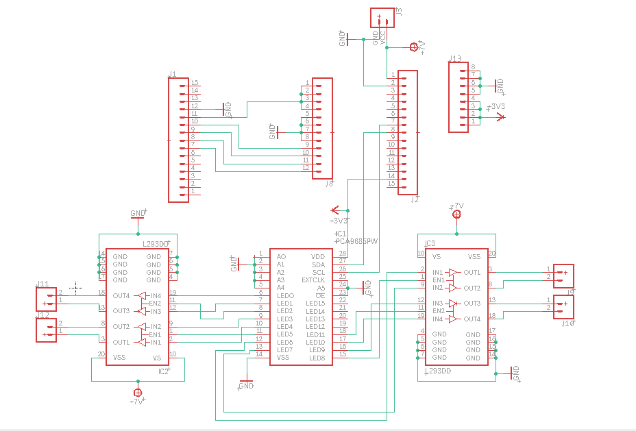
The schematic for the PCB board of the Nano Every can be found below, in the image we can see that it’s very similar to the one for the 3Dot except it uses the nano as the controller instead. It also has additional connectors for the photo interrupters.
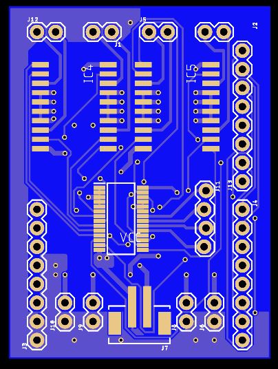
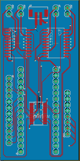
Below is the board layout for the nano every v2 shield. It adopts the star configuration for the power like the final 3Dot board. The 2 mm connectors can be seen at the top,which were implemented to save space. This design has ground distributed on the entire bottom of the board and doesn’t have unnecessary ground planes on the top side which ultimately resulted in it being our final board for the Nano.
Firmware
The firmware of Limbi is implemented to control each individual joint, up to an angle of 255 degrees, locally. Meaning to say, the firmware allows for the joints to rotate specific angles, but does not track the previous angle location. We had a total of 3 custom commands for Limbi, as we made use of the move command to define which direction we wanted to turn for both the motors controlling the joints on Limbi, and the motors controlling the androgynous connectors on the ends of Limbi. The three custom commands we implemented were to select which motor we wanted to use, via a series of radio buttons, named MOTOR. A slider/stepper which was used to input the amount of degrees we wanted to obtain from the motor named MANGLE, which would then turn the specified angle using the tank slider controls. Lastly we had a command labeled debug which was a simple LED command used to turn on and off the on board LED of the 3Dot, to verify if we were still communicating to the board.
In total there were 6 radio buttons for Limbi, one for each joint motor and 2 for the additional motors at the end of Limbi, although it only allows for one motor to move at a time, it is useful in ensuring that Limbi never goes above it allotted power consumption and only uses its motor function when necessary.
Below is the Final version of our code for Limbi, allowing full motor control
#include  //Adafruit servo library Driver
#include
#include
#include  // ready for Dot shields
Adafruit_PWMServoDriver pwm = Adafruit_PWMServoDriver();
ArxRobot ArxRobot; // make a 3DoT Robot
int MotorOnLeft = 0;
int MotorOnRight = 0;
int MotorNumber = 1;
//Arduino PWM Speed Control:
int encoder0Pos = 0; //Angle position of encoder 0
int encoder1Pos = 0; //Angle position of encoder 1
int encoder2Pos = 0; //Angle position of encoder 2
int encoder3Pos = 0; //Angle position of encoder 3

int encoder0 = 22;
int encoder1 = 14;
int encoder2 = 15;
int encoder3 = 16;

int last0state = 0; // beginning state of motor 0
int last1state = 0; // beginning state of motor 1
int last2state = 0; // beginning state of motor 2
int last3state = 0; // beginning state of motor 3

int angle = 1;
#define MANGLE 0x42 // Custom command Mangle being added
#define MOTOR 0x50 // Custom command Motor being added
#define MOVE 0x01 // Command Move being added
#define LIGHT 0x46 // Custom command Light being added
const uint8_t CMD_LIST_SIZE = 4;
void LightHandler (uint8_t cmd, uint8_t param[], uint8_t n);//Creates a handler for the light command
void MoveHandler (uint8_t cmd, uint8_t param[], uint8_t n); //Creates a handler for the move command
void MotorHandler (uint8_t cmd, uint8_t param[], uint8_t n); //Creates a handler for the Motor command
void MangleHandler (uint8_t cmd, uint8_t param[], uint8_t n); //Creates a handler for the Mangle command
ArxRobot::cmdFunc_t onCommand[CMD_LIST_SIZE] = {LIGHT,LightHandler, MOVE,MoveHandler, MOTOR,MotorHandler, MANGLE,MangleHandler}; // enabling all custom commands


void setup()
{
Serial.begin(9600);
pwm.begin();
ArxRobot.begin();
ArxRobot.setOnCommand(onCommand, CMD_LIST_SIZE);
pinMode(LED_BUILTIN, OUTPUT); //Setting the Built in LED into an ouput
}

void loop()
{
ArxRobot.loop();
////////////////////////////////////////////////////////////////
if (MotorNumber == 1 && MotorOnRight == 1) {
encoder0Pos = 0;
pwm.setPin(9, 4095, false );
pwm.setPin(10, 0, false );
pwm.setPin(11, 4095, false );
if(angle<=50){
while(encoder0Pos <= angle*(.13*(angle) + .5)) { int encoder0state = digitalRead(encoder0); if (encoder0state!=last0state){ if (digitalRead(encoder0) == LOW) { encoder0Pos++; } // Serial.println (encoder0Pos); last0state = encoder0state; } } } if(angle>50 && angle<=90) {
while(encoder0Pos <= angle*(.034*(angle) + 3.7)) { int encoder0state = digitalRead(encoder0); if (encoder0state!=last0state){ if (digitalRead(encoder0) == LOW) { encoder0Pos++; } // Serial.println (encoder0Pos); last0state = encoder0state; } } } if(angle> 90) {
while(encoder0Pos <= angle*(.006*(angle)+6))
{

int encoder0state = digitalRead(encoder0);

if (encoder0state!=last0state){
if (digitalRead(encoder0) == LOW) {

encoder0Pos++;
}
// Serial.println (encoder0Pos);
last0state = encoder0state;

}

}
}


pwm.setPin(9,0, false );
pwm.setPin(10, 0, false );
pwm.setPin(11, 0, false );

MotorOnRight=0;
}

if (MotorNumber == 1 && MotorOnLeft == 1) {
encoder0Pos = 0;
pwm.setPin(10, 4095, false );
pwm.setPin(9, 0, false );
pwm.setPin(11, 4095, false );

if(angle<=50){
while(encoder0Pos <= angle*(.13*(angle) + .5)) { int encoder0state = digitalRead(encoder0); if (encoder0state!=last0state){ if (digitalRead(encoder0) == LOW) { encoder0Pos++; } // Serial.println (encoder0Pos); last0state = encoder0state; } } } if(angle>50 && angle<=90) {
while(encoder0Pos <= angle*(.034*(angle) + 3.7)) { int encoder0state = digitalRead(encoder0); if (encoder0state!=last0state){ if (digitalRead(encoder0) == LOW) { encoder0Pos++; } // Serial.println (encoder0Pos); last0state = encoder0state; } } } if(angle> 90) {
while(encoder0Pos <= angle*(.006*(angle)+6))
{

int encoder0state = digitalRead(encoder0);

if (encoder0state!=last0state){
if (digitalRead(encoder0) == LOW) {

encoder0Pos++;
}
// Serial.println (encoder0Pos);
last0state = encoder0state;

}

}
}


pwm.setPin(9,0, false );
pwm.setPin(10, 0, false );
pwm.setPin(11, 0, false );

MotorOnLeft=0;
}

/////////////////////////////////////////////////////////////

if (MotorNumber == 2 && MotorOnRight == 1) {
encoder1Pos = 0;
pwm.setPin(3, 4095, false );
pwm.setPin(4, 0, false );
pwm.setPin(5, 4095, false );
if (angle<=50){
while(encoder1Pos <= angle*(.13*(angle) + .5)) { int encoder1state = digitalRead(encoder1); if (encoder1state!=last1state){ if (digitalRead(encoder1) == LOW) { encoder1Pos++; } // Serial.println (encoder1Pos); last1state = encoder1state; } } } if (angle>50 && angle<=90){
while(encoder1Pos <= angle*(.034*(angle) + 3.7)) { int encoder1state = digitalRead(encoder1); if (encoder1state!=last1state){ if (digitalRead(encoder1) == LOW) { encoder1Pos++; } // Serial.println (encoder1Pos); last1state = encoder1state; } } } if (angle>90){
while(encoder1Pos <= angle*(.006*(angle)+6))
{

int encoder1state = digitalRead(encoder1);

if (encoder1state!=last1state){
if (digitalRead(encoder1) == LOW) {

encoder1Pos++;
}
// Serial.println (encoder1Pos);
last1state = encoder1state;

}

}
}
pwm.setPin(4, 0, false );
pwm.setPin(3, 0, false );
pwm.setPin(5, 0, false );

MotorOnRight=0;

}
if (MotorNumber == 2 && MotorOnLeft == 1){

encoder1Pos = 0;
pwm.setPin(4, 4095, false );
pwm.setPin(3, 0, false );
pwm.setPin(5, 4095, false );
if (angle<=50){
while(encoder1Pos <= angle*(.13*(angle) + .5)) { int encoder1state = digitalRead(encoder1); if (encoder1state!=last1state){ if (digitalRead(encoder1) == LOW) { encoder1Pos++; } // Serial.println (encoder1Pos); last1state = encoder1state; } } } if (angle>50 && angle<=90){
while(encoder1Pos <= angle*(.034*(angle) + 3.7)) { int encoder1state = digitalRead(encoder1); if (encoder1state!=last1state){ if (digitalRead(encoder1) == LOW) { encoder1Pos++; } // Serial.println (encoder1Pos); last1state = encoder1state; } } } if (angle>90){
while(encoder1Pos <= angle*(.006*(angle)+6))
{

int encoder1state = digitalRead(encoder1);

if (encoder1state!=last1state){
if (digitalRead(encoder1) == LOW) {

encoder1Pos++;
}
// Serial.println (encoder1Pos);
last1state = encoder1state;

}

}
}
pwm.setPin(4, 0, false );
pwm.setPin(3, 0, false );
pwm.setPin(5, 0, false );

MotorOnLeft=0;


//////////////////////////////////////////////////////////////
if (MotorNumber == 3 && MotorOnRight == 1) {
encoder2Pos = 0;
pwm.setPin(6, 4000, false );
pwm.setPin(7, 0, false );
pwm.setPin(8, 4095, false );
if (angle<=50){
while(encoder2Pos <= angle*(.1*(angle) + .5) ) { int encoder2state = digitalRead(encoder2); if (encoder2state!=last2state){ if (digitalRead(encoder2) == LOW) { encoder2Pos++; } last2state = encoder2state; } } } if(angle>50 && angle<= 90){

while(encoder2Pos <= angle*(.032*(angle) + 3.5) ) { int encoder2state = digitalRead(encoder2); if (encoder2state!=last2state){ if (digitalRead(encoder2) == LOW) { encoder2Pos++; } last2state = encoder2state; } } } if(angle> 90){

while(encoder2Pos <= angle*(.007*(angle)+6))
{

int encoder2state = digitalRead(encoder2);

if (encoder2state!=last2state){
if (digitalRead(encoder2) == LOW) {

encoder2Pos++;
}

last2state = encoder2state;

}
}

}
pwm.setPin(6,0, false );
pwm.setPin(7, 0, false );
pwm.setPin(8, 0, false );

MotorOnRight =0;

}
if (MotorNumber == 3 && MotorOnLeft == 1){

encoder2Pos = 0;
pwm.setPin(7, 4000, false );
pwm.setPin(6, 0, false );
pwm.setPin(8, 4095, false );

if (angle<=50){
while(encoder2Pos <= angle*(.1*(angle) + .5) ) { int encoder2state = digitalRead(encoder2); if (encoder2state!=last2state){ if (digitalRead(encoder2) == LOW) { encoder2Pos++; } last2state = encoder2state; } } } if(angle>50 && angle<= 90){

while(encoder2Pos <= angle*(.032*(angle) + 3.5) ) { int encoder2state = digitalRead(encoder2); if (encoder2state!=last2state){ if (digitalRead(encoder2) == LOW) { encoder2Pos++; } last2state = encoder2state; } } } if(angle> 90){

while(encoder2Pos <= angle*(.007*(angle)+6))
{

int encoder2state = digitalRead(encoder2);

if (encoder2state!=last2state){
if (digitalRead(encoder2) == LOW) {

encoder2Pos++;
}

last2state = encoder2state;

}
}

}
pwm.setPin(6,0, false );
pwm.setPin(7, 0, false );
pwm.setPin(8, 0, false );

MotorOnLeft = 0;

}

////////////////////////////////////////////////////////////////
if (MotorNumber == 4 && MotorOnRight == 1) {
encoder3Pos = 0;
pwm.setPin(1, 4000, false );
pwm.setPin(0, 0, false );
pwm.setPin(2, 4095, false );


if (angle<=50){
while(encoder3Pos <= angle*(.1*(angle) + .5) ) { int encoder3state = digitalRead(encoder3); if (encoder3state!=last3state){ if (digitalRead(encoder3) == LOW) { encoder3Pos++; } // Serial.println (encoder1Pos); last3state = encoder3state; } } } if (angle>50 && angle <= 90){
while(encoder3Pos <= angle*(.0325*(angle) + 3.5) ) { int encoder3state = digitalRead(encoder3); if (encoder3state!=last3state){ if (digitalRead(encoder3) == LOW) { encoder3Pos++; } // Serial.println (encoder1Pos); last3state = encoder3state; } } } if (angle>90){
while(encoder3Pos <= angle*(.0055555*(angle)+6))
{
int encoder3state = digitalRead(encoder3);

if (encoder3state!=last3state){
if (digitalRead(encoder3) == LOW) {

encoder3Pos++;
}
// Serial.println (encoder1Pos);
last3state = encoder3state;

}


}
}

pwm.setPin(0, 0, false );
pwm.setPin(1, 0, false );
pwm.setPin(2, 0, false );

MotorOnRight=0;
}
if (MotorNumber == 4 && MotorOnLeft == 1){

encoder3Pos = 0;
pwm.setPin(0, 4000, false );
pwm.setPin(1, 0, false );
pwm.setPin(2, 4095, false );
if (angle<=50){
while(encoder3Pos <= angle*(.1*(angle) + .5) ) { int encoder3state = digitalRead(encoder3); if (encoder3state!=last3state){ if (digitalRead(encoder3) == LOW) { encoder3Pos++; } // Serial.println (encoder1Pos); last3state = encoder3state; } } } if (angle>50 && angle <= 90){
while(encoder3Pos <= angle*(.0325*(angle) + 3.5) ) { int encoder3state = digitalRead(encoder3); if (encoder3state!=last3state){ if (digitalRead(encoder3) == LOW) { encoder3Pos++; } // Serial.println (encoder1Pos); last3state = encoder3state; } } } if (angle>90){
while(encoder3Pos <= angle*(.0055555*(angle)+6))
{
int encoder3state = digitalRead(encoder3);

if (encoder3state!=last3state){
if (digitalRead(encoder3) == LOW) {

encoder3Pos++;
}
// Serial.println (encoder1Pos);
last3state = encoder3state;

}


}
}

pwm.setPin(0, 0, false );
pwm.setPin(1, 0, false );
pwm.setPin(2, 0, false );

MotorOnLeft=0;

}

///////////////////////////////////////////////////////////////

if (MotorNumber == 5 && MotorOnRight == 1){

digitalWrite(12,HIGH);
digitalWrite(4,LOW);
digitalWrite(6,HIGH);
digitalWrite(8,HIGH);


}
if (MotorNumber == 5 && MotorOnLeft==1){

digitalWrite(12,LOW);
digitalWrite(4,HIGH);
digitalWrite(6,HIGH);
digitalWrite(8,HIGH);


}
if (MotorNumber == 5 && MotorOnRight == 0 && MotorOnLeft == 0){

digitalWrite(12,LOW);
digitalWrite(4,LOW);
digitalWrite(6,LOW);
digitalWrite(8,LOW);


}

if (MotorNumber == 6 && MotorOnRight == 0 && MotorOnLeft == 0){


digitalWrite(8,LOW);
digitalWrite(9,LOW);
digitalWrite(5,LOW);
digitalWrite(10,LOW);


}
if (MotorNumber == 6 && MotorOnRight == 1){

digitalWrite(9,HIGH);
digitalWrite(5,LOW);
digitalWrite(10,HIGH);
digitalWrite(8,HIGH);


}
if (MotorNumber == 6 && MotorOnLeft==1){

digitalWrite(9,LOW);
digitalWrite(5,HIGH);
digitalWrite(10,HIGH);
digitalWrite(8,HIGH);


}
}

void LightHandler (uint8_t cmd, uint8_t param[], uint8_t n) //Utilizing the Light handler command for debugging
{
if(param[0] == 1 ){ // Using boolean: if button = 1 = Onboard 3dot Light = ON
digitalWrite(LED_BUILTIN,HIGH);
}
else{ // Else: button = 0 = Onboard 3dot Light = OFF
digitalWrite(LED_BUILTIN,LOW);
}
}
void MoveHandler (uint8_t cmd, uint8_t param[], uint8_t n) //Utilizing the Move handler command for determining angle direction
{
if(param[0] == 1){ // if param 0 = 1, Move motor to left
MotorOnLeft = 1;
}
if(param[0] == 2){ // if Param = 0 = 2, Move motor to Right
MotorOnRight = 1;
}

if(param[0] == 4){ // if Param = 0 = 4, dont move
MotorOnLeft = 0;
MotorOnRight = 0;
}

}

void MotorHandler (uint8_t cmd, uint8_t param[], uint8_t n) //Utilizing the motor handler command for determining which motor we want to select
{
MotorNumber = param[0];
}

void MangleHandler (uint8_t cmd, uint8_t param[], uint8_t n) //Utilizing the Mangle handler command for determining which angle we want to select
{
angle = param[0];


}
Initialization
Based off the code above, you can see that our initialization is a lengthy portion of the code. In this section we include the Adafruit Library, to control the encoders on our motors, the ArxRobot library to allow communication to and from the Arxrobot App, and the wire library for any attached 3Dot shields as well as the EEProm for memory purposes. After this we initialize all our variables including the encoders, motors, their on and off states and their starting and ending positions. Shortly after this, we define our custom commands and their respective handlers, enabling these commands to be placed within the ArxRobot Library so that the App and code can communicate with one another. Lastly our void setup is simple and contains only commands used to initialized the serial port, the PWM control and the ArxRobot control, as well as establishing the builtin LED as an output
Void Loop
The Void loop subroutine is the heart of the control for Limbi, as it is what controls the pins that our encoders and motors are connected to. We can see that based on the motor selection, and the motor rotation selection, specific the micro controller is told which motor to move and what direction to turn, which is really just setting a specific pin number on the board itself, the pins alternate between High and Low depending on the direction we choose to rotate. After this, we read the angle the user has inputted and the angle goes through a series of calculations to convert the angle into the correct encoder position, so that the desired angle may be achieved. This is repeated for every possible motor and every rotation of that motor, for a total of 8 times, just on the joint motors alone.
Handlers
Finally, after the end of the Void loop, we can see our light handler, move handler, mangle and motor handler. The light handler runs a simple if statement that determines if the Boolean switch is on or off, to turn the light on or off like a light switch. The Move handler checks the first parameter of the move command, to determine if the tank controls are up or down, which indicates either left or right. If the value of parameter 0 is a 1, then we move left, if its a 2 then we move right, and if it is a 4 then we don't move at all. After this both the Motor and Mangle handlers are simple and set to read the values of param 0, which are then inputted into a global variable to be read off by the Void Loop.
Mechanical/Hardware Design
This section lists the three main mechanical features of Limbi: the Arm itself, the androgynous connectors, and the cubic modules. It shows the progression of the three as they went through several design changes throughout the course of the semester.
This first link provides a overview of all the generations and design iterations we went through for the cubic modules.
This second link provides a view of all the different 3D prints we conducted, including Limbi itself, during the course of this class we obtained a strong understanding of 3D printing and how the different materials provided, are useful in different scenarios.
This third link gives an overview of all the iterations of our androgynous connectors, and even early concept art of designs that we ultimately scrapped, but may want to be investigated for future generations.
Verification & Validation Test Plan
The final document can be found in this link
For Limbi Gen 2, we verified that our design meets the requirements through the Verification Test Plan, by creating a test plan, to test the various level 2 requirements in sequence. We had 3 separate test cases for Limbi Generation #2, With the first test case pertaining to anything concept related, including the overall design and aesthetics of Limbi. This test case featured many "will" requirements, where Limbi and the modules were inspected or measured using a caliper tool to ensure their proper visual design and size limits. Test case 2 was designed for anything pertaining to the motors and movement of limbi, which focused on angle accuracy for each joint, the connectors having the ability to rotate and dock, and the overall power consumption of the motors themselves. Examples of the requirements within this Test case include, ensuring Limbi is controlled by 4 separate micro metal gear motors, or ensuring the androgynous connector allows for docking between Limbi and the modules themselves. The final test case was for Bluetooth control with the integrated ArxRobot app, allowing Limbi to be controlled wirelessly with custom commands through the ArxRobot app. The test cases T-2 and T-3 both assumed Limbi had already been built as well as the cubic modules, so that we did not have to spend time assembling Limbi. Our test plan revolved around Starting Limbi, checking for angle accuracy via the Bluetooth commands, attempting to dock via the Bluetooth commands, and eventually combining two cubes together as per Limbi's mission objective.
Concluding Thoughts and Future Work
The following is a list of how Limbi can be improved in future generations, based off what worked for us and what did not:
- Make sure to stick to materials such as ONYX and ABS to minimize the weight of the limb and cubic modules
- Try to make the modules as small and as light as possible, so that Limbi doesn't have to work as hard to move a module
- The Androgynous connector is a must, however do not forget to make it easy to dock, as ours was not, as it did not have enough leeway when the soft dock system was engaging.
- Make sure the Androgynous connector does not need much movement to lock into place, and ideally, make it so that the connector does not require any movement once the soft lock as engaged.
- Do not leave the design, or underestimate the design of the modules, as in the end they were as complicated if not more complicated than Limbi itself
- Do not stray away from an androgynous design, as the official NASA docking design is androgynous, and future teams may be able to learn from their designs, and try to implement a small scale version.
- Always try to rapid prototype using ABS and leave onyx for the final design, Also the measurements between ONYX and ABS differ slightly due to the nature of the material, so what might work in ABS may not work in ONYX and vice versa
- Make sure the motors you purchase have as much torque as possible and have a good encoder within them to control their angles. Would recommend purchasing micro metal gear motors again, but do not purchase the micro planetary motors as they gave us many troubles.
- Be careful with press fit designs as plastic changes over time and it wears down and will not fit as well as it did initially, over time.
- Try to avoid the usage of magnets or motors all together within the modules themselves, if possible make the cube as passive as possible
- Do not forget about the wiring, or leave it to the last minute, when creating Limbi, always consider how the wiring will look, when designing.
- Don't be afraid to spend money on the motors, as they are the main aspect of limbi, that allows it to work, and the motors are what take the majority of the strain when Limbi is connecting modules together.
- Do not worry about calculating or simulating Limbi, it is better to just rapid prototype and see what works, as the calculations for Limbi are very complicated and will take a lot of time to calculate unless you know the exact formulas needed from the beginning
- Be careful with the modular contacts if using again for power/data transfer, as they do not always work, even when lined up perfectly, they still require some pressure between them to function properly
- Would not recommend straying away from the limb-over-limb design, where limbs 1 and 3 are below 0,4 and 2. This allows the modules to line up perfectly with the limb, without having to raise Limbi up through other means such as through its ball casters.
- Ball casters are not necessary, would recommend designing some sort of points or downward facing cones at the bottom of limbs 1 and 3 so that it is hardly making any contact with the surface beneath it.
In the future, if we were to continue this project, the first thing we would do is replace the motors with some that turn slower, remember the slower the RPM, the more accuracy you can obtain from the motors, as there is less of a chance of missing the angle you wish to obtain.
References/Resources
These are the starting resource files for the next generation of robots. All documentation shall be uploaded, linked to, and archived in to the Arxterra Google Drive. The “Resource” section includes links to the following material.

