Limbi: Preliminary Design
Table of Contents
Project Objective/ Mission Profile
By: Alondra Vivas
Project Objective
We plan to continue the advancement of NASA JPL’s Limbi, a multi-jointed robot that allows for the connection of two modules through their docking mechanisms. The goal is to improve on the current Limbi by developing a mechanical androgynous connector for Limbi as well as the cubic modules, reduce the overall size and mass of NASA JPL’s Limbi, allow power transfer to flow from the cubic modules to Limbi and between each other, replicate space by creating a low friction environment, and reducing the cost of the overall project.
Mission Profile
The purpose of Limbi is for astronauts to create structures autonomously in space that would reduce the time, risk, and cost of building the structures. Utilizing the idea of Legos, the cubic modules can be used to build space stations, large solar panels, and space laboratories for safer and more efficient experiments.This would be accomplished by having Limbi pick up one cubic module with its connector, attach it to another cubic module while remaining attached to the second cubic module,the next step would be to pick up another cubic module and repeat the process over again.
Project Requirements
By: Alondra Vivas
The second generation Limbi follows the Level 1 requirements of the first generation Limbi with a few adjustments, to compare see Limbi geration 1 requirements. These requirements must be accomplished while also taking in to consideration that this project is meant to be used in space.
The picture below is a requirement tree showing how Limbi Generation 2 is neither over designed nor undersigned.
Engineering Standards and Constraints
- The Limbi shall employ a custom PCB to extend the functions of the Arduino Nano and the 3Dot by allowing control of 4 micro metal geared motors, 2 micro planetary motors, 2 electromagnets, and Arduino Nano communication.
- Disassemble and Reassemble of the robot shall be constrained to less than 20 minutes (10 minutes+10 minutes).
- The Limbi shall be completed by the date of the final: December 17th 2019.
- The robot shall be designed in such a way that there are no dangling or exposed wires via cable wrap.
- The form factor of Limbi shall be constrained by the original JPL version.
- The usability of the Limbi shall be enhanced by use of the Arxterra phone and control panel application
- The ArxRobot app shall allow control of all joint motors and docking motors (see requirement L 1.10)
- Manufacturability of 3D printed robots shall minimize the number of files to be printed when using the library’s Innovation Space to print the final robot.
- All Lithium (Li-ion, Li-polymer) batteries shall be stored, when not in use, in a fire and explosion proof battery bag.
- Software shall be written in the Arduino De facto Standard scripting language and/or using the GCC C++ programming language, which is implements the ISO C++ standard (ISO/IEC 14882:1998) published in 1998, and the 2011 and 2014 revisions.
- The Limbi shall be controlled via Bluetooth 4.0 in compliance with the Bluetooth Special Interest Group (SIG) Standard (supersedes IEEE 802.15.1).
Level 1 Program and Project Level Requirements
L.1.1) Shall implement a low friction surface to simulate the environment in space.
L.1.2) Shall make Limbi Shorter than the JPL Limbi for storage and rapid prototyping purposes. Limbi will be smaller by approximately 50% of the original size of the JPL design.
L.1.3) Shall move each of the arm’s 4 joints according to their attached limbs, with 4 of the 5 limbs moving in total and the final limb acting as a stabilizer.
L.1.4) Will have each joint contain at least 270 degrees of motion in one plane (x-y).
L.1.5) Shall have the arm connect and disconnect with the cubic modules.
L.1.6) Shall include a docking mechanism to keep the arm and module connected as the arm moves until it is meant to be disengaged.
L.1.7) Shall have the arm contain a docking mechanism on each end to connect to two modules at once.
L.1.8) Shall have the arm be able to move the module in one plane (x-y).
L.1.9) Shall have the arm be able to lock two modules together through a mechanical design.
L.1.10) Shall be able to control the movement of the arm by the user with custom software.
L.1.11) Shall have Limbi controlled with a micro controller (3Dot).
L.1.12) Shall have each cubic module be capable of providing power to the arm and to the other cubic modules.
L.1.13) Should have Limbi and the cubic modules be powered with a single rechargeable battery per module/Limbi.
L.1.14) Will have dock on 4 of the faces of the cubic modules for demonstration purposes.
L.1.15) Should have the module indicate when a secure connection is made between the Limbi and modules with an LED.
L.1.16) Shall have one module as the base module and shall be stationary to represent a large, unmoving mass in space. This requirement is base on Section 4 of “An Untethered Mobile Limb for Modular In-Space Assembly.”
Level 2 Program and Project Level Requirements
L.2.1) Limbi will be supported with 8 small nylon metallic ball casters (each weighing 5.0g) on Limb 1 and Limb 3 to simulate the conditions where the arm will not be affected by gravity.
L.2.2)Limbi will follow the form factor of the JPL version; the lengths will be optimized in respect to inverse kinematics.
L.2.3.1)Each joint shall control 2 limbs at a time.
L.2.3.2)Joint 1 shall control the motion between Limb 0 and Limb 1.
L.2.3.3)Joint 2 shall control the motion between Limb 1 and Limb 2.
L.2.3.4)Joint 3 shall control the motion between Limb 2 and Limb 3.
L.2.3.5)Joint 4 shall control the motion between Limb 3 and Limb 4.
L.2.4.1)Limbi will have 4 joints controlled by micro metal gearmotors.
L.2.4.2)Each micro metal gearmotor shall require no more than 6V to run with a load.
L.2.5)The docking mechanism shall consist of the mechanical androgynous connector described, to allow Limbi to successfully attach and detach to and from the module.
L.2.6)Only 1 docking DC motor shall be in motion at once, so the module does not un-dock while the other module docks.
L.2.7)The docking mechanisms on each end will be identical to each other.
L.2.8)The micro metal gearmotors shall be able to provide more than 2.5 kg.cmor 0.245 Nm based on the force to move an object in a planar field.
L.2.9)The mechanical design of the connectors must be strong enough so that constant power from electromagnets are not required to attach or detach them.
L.2.10.1)The user interface shall utilize wireless Bluetooth to control Limbi.
L.2.10.2)The custom software will be implemented through the Arxterra App.
L.2.10.3) The user interface shall have push buttons/toggles for pre-determined movements.
L.2.10.4) The user interface shall use simulated sliders for manual movements.
L.2.11) The project will use a 3dot board mounted within the Limbi arm to allow the 4 micro metal geared motors and 2 micro planetary motors to be controlled directly by the microcontroller.
L.2.12) The power provided from the module shall come from a battery (5V) via the docking mechanism.
L2.13.1) The battery for limbi shall be capable of providing 1055 mA current (if needed) which will be used to power the 3dot, the motors, and the electromagnets.
L.2.13.2) The battery used will be a rechargeable Lithium Ion battery weighing 22g each and using 1.5V each.
L.2.14.1) The module shall have an androgynous connector on all 4 faces, with the top and bottom faces remaining empty to allow ease of access to the electronics within, and for a location for the casters.
L.2.14.2)4 faces on the cubic module will serve for both interconnections among each other and to connect to Limbi.
L.2.15.1) The LED on the module should be activated by one of the four power connections. Verification through testing.
L.2.15.2) The LED should be on the corner so the person controlling the app can easily see that a secure connection has been made. Verification through demonstration.
L.2.16)The arm shall be attached to a module at all times. Verification through demonstration.
System Design
System Diagram
By: Alondra Vivas
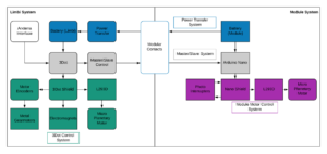
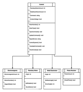
Limbi Generation 2 will be split in to two separate systems: Limbi and the module. Limbi’s system consists of the arxterra interface, power transfer, and the 3Dot control system. The module’s system contains the power transfer system, master/slave system, and the module motor control system. A detailed breakdown is shown in the diagram below.
Design & Manufacturing
By: Edward Villanueva
This section contains the information where the reader can see our design process and ideas. You will find the SolidWorks drawings, why we went with those designs, and how each component will be placed within Limbi and the modules.
Limbs
Design
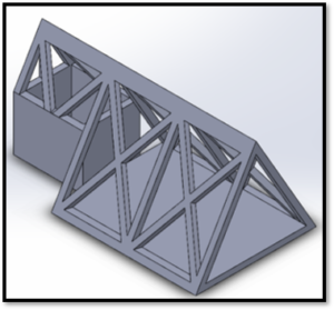
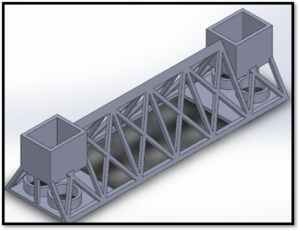
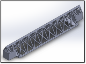
The Truss design was implemented because it is part of space architecture. It has proven to be lightweight and strong. Another common design method within space architecture is a rectangular design. However, we found that this design implementation makes placing the 3Dot within limb 2 impossible unless that limb gets larger but due to our requirements we are restricted on the size. All limbs require a height and width of 4.3 cm in accordance to the triangular truss design. In future iterations we are going to make the limbs in to a rectangular design.
Joints
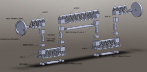
Limbi has 4 joints, one per each limb connected and 2 at the ends of limbs 0 and 4 for a total of 6 articulation points. The joints between each limb connection take 1 micro metal geared motor. The joins at the end of limbs 0 and 4 take 1 micro planetary gear motor to rotate the androgynous connectors. The joints for the micro metal geared motors contain a top and bottom piece in order to hold the base of the motor and the shaft of the motor in place.
Androgynous Connectors
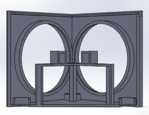
We have had separate ideas regarding the androgynous connectors. There are several requirements that are needed within the connectors, to ensure that modules can be docked to Limbi and one another, with minimal difficulties. Limbi has 2 connectors on each end while each cubic module contains 4 connectors on each face except the top and the bottom.
Module Requirements:
- The connector needs to have a mechanical lock, so that a constant power source is not required to stay locked into place.
- The lock must be rigid so that long chains of blocks stay stable and do not fluctuate.
- The connection must have a soft-docking feature, meaning excessive force is not required to connect the two modules together, as this would prove troublesome in space, where there is no friction to stop a floating module.
Androgynous connector ideas:
- Snap rivets in conjunction with Velcro, which would allow for a simple push to lock the connectors in place.
- A fire hose type connection, in which two androgynous connections are placed facing one another, and both twisted clockwise to create a nearly inseparable bond between the two connectors.
- A bottle cap connection, in which one connector screws into the other, creating a bond that could only be unscrewed to separate.
- A screw method that would see 2 screws and two threaded holes per box, and when coming together, the screws would be screwed into the threaded holes to create the bond.
After careful consideration we realized the design with the tighter seal is the fire hose connection with an implementation of the bottle cap. The design can be seen below as well as a simulation.
Cubic Modules
Module Design
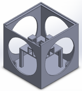
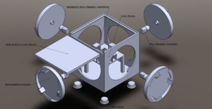
The cubic modules are the “building blocks” of Limbi which are used to create autonomous structures in space. Each feature 4 androgynous connectors connected to 4 micro planetary gear motors. The connectors are neither on the top nor the bottom. The top of the module has a slide fit for quicker access to the inside of the module. The bottom of the module contains 4 ball caster to mimic the environment of space. Motors are essential within the modules to rotate each connector, therefore, it has its own micro controller to control the motors and the power transfer between Limbi. The cube will communicate to Limbi through the modular contacts.
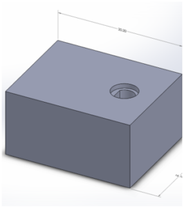
The SolidWorks design is shown below. The ball casters are press fit as well as the motors. There are mounts in the module were the motors can be press fitted within in order to control the connectors.
Sleeve Design
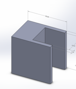
A sleeve design had to be implemented within the newer versions of the modules. This was meant to retain androgynous connectors in place, while simultaneously removing the load off the micro planetary motor that will rotate the motor. This design should allow for ease of entry of the androgynous connector through the front face.
3D Print Material
Limbi has been and will continue to be printed in the Innovation Space Center through the semester. The reason being is that they have a Markforged 3D printer which very few places have. They are also cost efficient being that provide student discounts and only charge for the materials. It was crucial to use this type of printed because we decided to go with the Onyx material, a mix of nylon with chopped carbon fiber embedded to create a lightweight material. It has the strength of aluminum and is flexible unlike the other materials they offer.
Exploded Views
Limbi
Limbi’s exploded view contains all of the components and elements that make up Limbi. In it you will see the motors, the joints, the connectors, the limbs, the press fit on the base of the limbs to get to the PCB quicker, and the ball casters on the bottoms. The exploded view was made by Edward Villanueva in SolidWorks.
Cubic Module
The cubic module’s exploded view contains all the part that make it up. You will notice the slide top for quicker access to the components, the motors with contain a press fit mount and a the shaft has a press fit to the back of the connectors, the ball casters, and a table like design is in the middle of the module to place the PCB underneath. The design was made by Edward Villanueva through SolidWorks.
Low Friction Surface
By: Alondra Vivas
In order for the motor to work on Earth as it would in space we would need a low friction surface. The friction coefficient in space is 0. On Earth it is extremely difficult to achieve this friction coefficient.
Types of low friction surfaces:
- Ice has a friction coefficient between 0.04-0.05. An issue with using ice as our friction less surface is in that we would have to take Limbi to the Ice Rink each time we need to test it which would result in schedule conflicts.
- Hockey tables have a friction coefficient of 0.01-0.03. The tests to figure out the friction coefficient of a hockey table have been tested when there is a puck on the table. We are hesitant to use the hockey table because it would be cost inefficient, would take a considerable amount to be built, and it would be problematic to transport.
- Dry sprays have a coefficient of friction of 0.04-0.05, making them about as friction less as ice. The added convenience is the spray could be placed on any surface to reduce the overall friction, and the surface, such as a fold table table could be taken with us very easily.
Due to the time restrictions in this semester, we will not be able to use any of the above surfaces. Neither NASA JPL nor Limbi Generation 1 used a specific surface, rather they both used ball casters. We will also be going with this approach on the ball casters, our improvement is that we found small enough casters that make the movement easier which causes the replication of space due to its low friction. The link to them can be found by clicking: Ball Casters.
Motor Comparison
By: Alondra Vivas
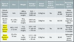
NASA JPL used a Schunk Univeral Rotary Actuator. The IEEE article they published was not very detailed on which specific motor they used. Therefore, the price of the motors is between $200- $1500 which is still highly above the student budget. The motor also weight approximately 1800g based on the datasheet assumed they used. It also used a current of between 1500mA and 5600mA, the reason for this his current is because these motors are known to have a precision of 99.99% making them unmatched to any other motor on the market. However, due to the high price and current, it is unrealistic within our student senior design. The article that explains the motor used is found here:
The first generation Limbi used servos in each of the joints. The team told us to steer clear of using them. The problem with using servos was that it added more overall mass to Limbi, was tougher to work with, and would create an unbalance where the servo could not hold a limb in place. The motor they used is found here: Limbi Generation 1 Summary Post.
Due to this analysis, the motors picked are the micro geared motor and the micro planetary motor. The micro geared motor is perfect for movement of the joints within Limbi, it’s lightweight at 12g, contains a built-in encoder, and is small. The micro planetary motor is ideal for the cubic modules by being light weight at 4g, small, and is inexpensive. Below is a chart the contains the pros and cons of each motor.
Electronics & Control
Power Transfer
By: Alondra Vivas
The power transfer allows for power to be transferred between Limbi and cubic modules. The way it will be accomplished is by using string pins and exposed copper pads on the contacts. The male contacts used are found here: Male Contacts.The female contacts used can be found here: Female Contacts. Both female and male contacts are required on each face of the cubic module. The positioning would be on the top corners of each face except the top and bottom. This design was chosen due to the fact that communication from Limbi to the module will also take place through the contacts. A consideration was to take the contacts and place them within the connectors themselves but due to the mounts of the motors, wiring issues arouse due to the connector moving.
Photo-Interrupters
By: Alondra Vivas
Photo-interrupters contain a beam emitter on the upright photo-interrupter. Once the upright detects an object blocking it, the power shuts off. The purpose for us using them is to allow us to get accurate angles on the rotation. They will be placed behind the androgynous connector so that when it rotates the flags that are in between the photo-interrupters will disrupt the beam and stop rotating. The photo-interrupters we are using are found here: Photo-Interrupters. Below is a rough sketch of the placement of the photo-interrupters within the connectors.
Electromagnets
By: Alondra Vivas
Solenoids are required to keep the connectors in place while they rotate to seal together. They will have to contain a metal washer in the center of the module’s connectors. The solenoids will be placed within Limbi’s connectors. Once the connectors get close together, the solenoid will turn on, becoming attracted to the metal washer. Power will then cut off automatically once they are sealed in place.
Microcontroller Electronic Design
By: Colin Rogers
This section pertains to everything involving the micro controllers used within Limbi and the cubic modules.You will find everything that will be connected to the 3Dot and the Arduino Nano. For clarification, we will be be using the 3Dot within Limbi and the Arduino Nano within the cubic module.
Schematics
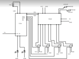
The 3Dot is the “brain” of Limbi. It will be responsible for controlling all aspects of the unit. The limbs, electromagnets, and connectors will all be controlled by a GUI on a remote computer via Bluetooth. This allows the user to communicate with the 3Dot directly and in turn control the Limbi. The cubes also need to be arduino controlled. This allows all the connectors on the cubes to be individually controlled.
Important Points
- 3Dot will be used for Limbi
- Will be controlled by a remote computer
- Cubes will be arduino controlled
- Cubes will be controlled independently of Limbi
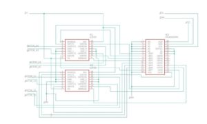
Limbi contains the 4 motors, the 3Dot and the shield, the solenoids, and the contacts. Since the 3Dot has a limited number of pins, we will have to use the I2C GPIO port.
The cubic modules have the 4 motors, the arduino nano, the contacts, and the photo interrupters.
Below are the Limbi schematic, shield schematic, and cubic module Schematic respectively.
Fritzing Diagrams
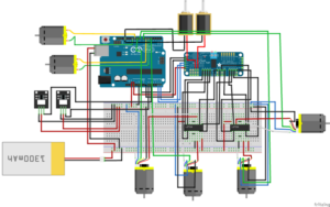
Below are the fritzing diagram for both Limbi and the cubic modules. It’s the connections that will be placed on the breadboard to get the other electronic components working accordingly. Both diagrams also contain the micro controllers and the shields.
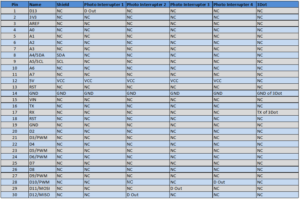
Arduino Nano Interface Matrix
Software
Software Design
By: Colin Rogers
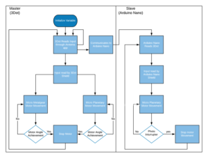
The software is separated between the master (3Dot) and the Slave (arduino nano). The idea with the code is that the user can initialize a variable after which the 3Dot reads the input through the ArxRobot App and is splits in to communication with the arduino nano and the input being red by the 3Dot. A more detailed description can be found on the image below.
App Customization
By: Edward Villanueva
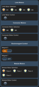
The first image below shows a screenshot taken of the ArxRobot app customized for Limbi Generation 2. We will have the control for the motors within Limbi and the cubic models, electromagnet control and the connector motors for Limbi. The electromagnets can simply be turned on or off. The motors are also turned on or off for the rotation. The motors for Limbi will have sliders on them for better precision.
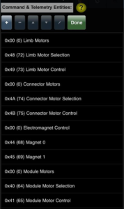
The second image below shows the commands that are being read to from the code on to the app itself.
Firmware Customization
Project Planning
By: Alondra Vivas
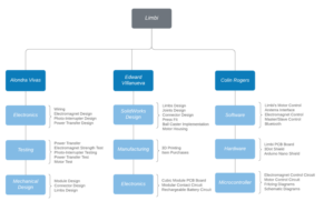
This project was done during the semester where the group projects were a matrix, therefore the work has been split up between our 3 group members. This section analyses the breakdown of the work between the members, the schedule, and the allocations.
Work Breakdown Schedule
Alondra Vivas is responsible for the wiring within Limbi and the cubic modules, documenting any testing being done as well as push for the tests to get accomplished at a reasonable time frame, and helping to provide ideas for the mechanical design of some components.
Edward Villanueava has the responsibility of creating all the SolidWorks drawings, any manufacturing being done including 3D printing and item purchases, and the electronics within the PCB board, as well as helping on the code.
Colin Rogers is responsible for the software of the motor control and bluetooth, the PCB board within Limbi, and any EagleCAD drawings that are required.
Below is a more detailed image of the WBS.
Design & Unique Tasks
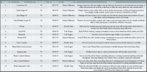
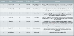
Schedule to accomplish V2 Demo
Schedule to accomplish the Final Demo
Project Schedule
This section contains detailed information on the progress accomplished thus far and what still needs to get done.
 Loading...
Allocation
Mass Report
The measured total mass of Limbi came out to be 243g, the cubic module at 408g, giving the total of Limbi attached to a single module to be 651g. Limbi Generation 1 had a total actual weight of 1446g this can be found on their Summary Blog Post. We managed to reduce the total weight of Limbi drastically. Below is a detailed mass report.
Size Report
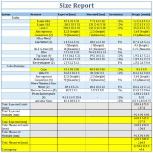
The measured total size of Limbi came out to be 548X199X216.5mm, the modules at 90X90X90 mm, giving the total of Limbi plus the module attached to it to be 638X289X216.5mm. The reason why the size changed slightly was due slight human error with the 3D prints A detailed size report is found below.
Power Report
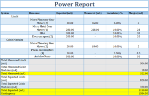
The measured current between Limbi and the module came out to be 322mA. The expected current is 1150mA, the reason for the drastic diference between both numbers is that not electronic component has been purchased therefore we could not get the total measure current. Regardless, 1.15A is plenty of current that can be supplied by the battery.
Cost Report
The total amount of money we have spent on this project has been $212.64 however since not all the material have been purchased we estimate the actual cost to be around $467.71 with a contingency of $495.67.
 Loading...


