Limbi Spring 2019
Limbi System Block Diagram Iterations
Author/s:
Julie Liner (Missions, Systems, and Test)
Table of Contents
Introduction
Over the course of the semester, the Limbi project went through several iterations. This blog post reviews some of the critical iterations that we went through starting with our original idea of the Limbi, our PDR view of the Limbi, and our current (post CDR) view of the Limbi. Assumptions that we kept throughout the entire project were that the Limbi would have modules that provided power through a docking mechanism. We always assumed that there would be a microcontroller and bluetooth connection that would control the movement of the Limbi arm. We also kept the assumption that there would always be two modules and the Limbi arm would have the ability to dock on two ends. Though the Limbi changed many times throughout the semester, it retained these main components that help define the Limbi.
Iteration 1
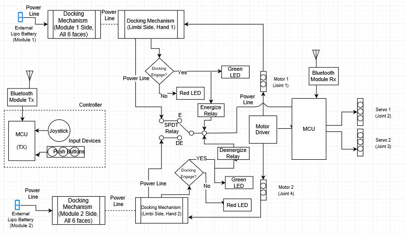
The Limbi has changed significantly since our first iteration, and we found many errors in our original concept. A big error in our first iteration was the assumption that we could use an SPDT Relay. The issue with this is that there would be a “break-before-make” circuit; the power would briefly shut off when transferring power from Module 1 to Module 2. This error would have proved catastrophic for the Limbi because it would lose all power and need to reboot the microcontroller. We also made the error of assuming that we would use manual joysticks or push-buttons. This assumption was made before we discovered the advanced and diverse abilities of the Arxterra Phone App and Control Panel. An additional error that was made was the set up of the block diagram and the use of conditional statements. Instead of showing the components that would be used to dock and energize the relay we just had a statement that if it docked we would confirm the docking with an LED and then energize the relay. This should have been replaced with the actual components that were represented in this interaction.We also made the assumption that the docking mechanisms would all be androgynous and cover all 6 faces of the Limbi; we soon realized that this was not possible within the time constraints.
Iteration 2
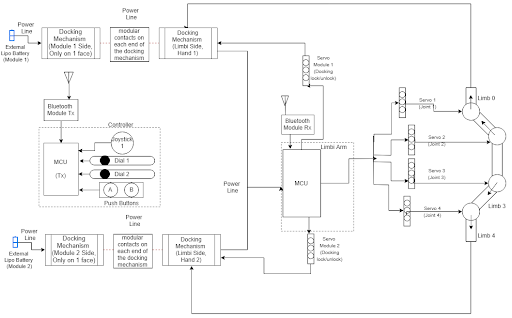
By the second iteration of our system block diagram we had a much better idea of what we wanted to do with the Limbi project. We had considered how we would transfer power from the battery within the module to the Limbi arm. We also corrected the “break-before-make” circuit to a “make-before-break” circuit, which would allow both batteries to power the arm before disconnecting from the original battery. We had also started looking into how to implement commands using the Arxterra App, which is shown in the “controller” box. At this point in the project we had a simple view of how the power would be supplied, but we had a good idea of what needed to be powered, as well as how many servos we were implementing to move the arm segments and the docking mechanisms.
Iteration 3
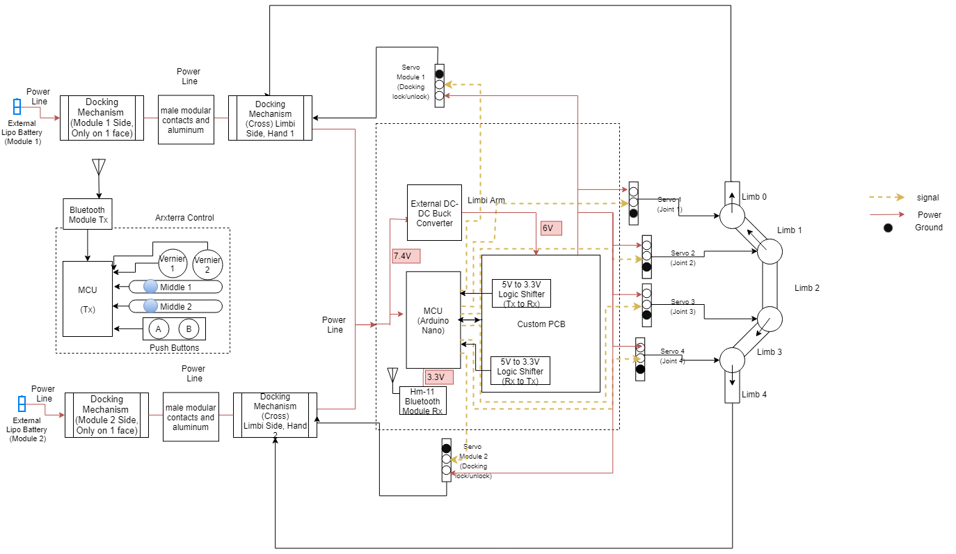
By the final iteration of the System Block Diagram we knew how power was going to be transferred and how all of the components would interface with each other. In this iteration our power goes through the module-to-arm face of the modules and transfers power between aluminum and male module contacts. This power is then delivered to the Arduino Nano and a buck converter. The Arduino Nano sends signals to the servos and to Hm-11. The buck converter delivers 6V to a custom PCB which is used to power the servos and a logic shifter used to step down the logic levels from the Arduino Nano to the Hm-11. Our docking mechanism was also updated to include a solenoid lock; this solenoid provided a positive locking system which ensured a secure connection between the module and the arm. Another change was the relation between the movement of joint 1 and Limb 0. With the assumption that Module 1 will be secured we know that moving joint 1 will not move Limb 0, but will move Limb 1 instead. The Arxterra commands have also been updated to replicate the options that we have: Vernier 1 and Vernier 2 control the end joints, Middle 1 and Middle 2 control the inner joints, pushbutton A and B control the docking servos and push-pull solenoids, and the joystick allows the use of inverse kinematics to allow the arm to move straight.
Conclusion
The Limbi has gone through many design iterations throughout the project as shown in the different iterations of the system block diagram. Throughout the course of the project we learned from our mistakes and continuously updated the Limbi design, requirements, and functionality which can be represented through our changing block diagrams. Through the use of ConOps and rapid prototyping we were able to expand the idea of Limbi from a simple block diagram to an intricate and realizable representation of the interfaces between components.


