Machine Code Workshop Lab 2: Line Follower
For the teacher
This is part two to Lab 1 of the Machine Code Workshops. All the software should already be installed and we will simply continue using the project files from last class. Click the button below if you need to re-download them. The code from last lab will be overwritten so a fresh copy is fine.
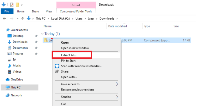
Right click the zip file downloaded and click “Extract All…”
Open the Lab 1 folder just extracted. You can delete the zip file.
Students Start Here!
In the last lab, we wrote 2 lines of code that showed us the robot was working properly. Now, let’s make it do something cool!
Step 1: Open the lab 1 folder from last lab
Step 2: Double click the file with the ladybug icon
Step 3: Scroll down to the code you wrote last lab and delete “out PORTD, r16”
Ok, let’s use the middle two sensors on the robot to follow a line.
To do this:
- we make the robot go forward
- while a sensor detects the black line, the motor on the same side stops
This way, the robot will adjust itself to get back on the line.
See the animation below to understand what I mean:
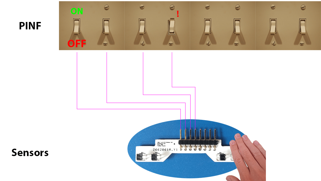
Remember these switches that the sensors were flipping last lab? Let’s wire them to the correct motors.
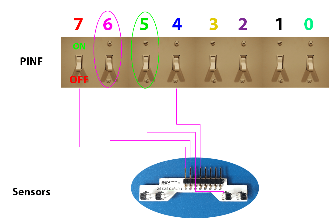
This is how the switches (also known as “bits“) are numbered in registers.
We start counting from zero, and count right to left.
If we look at the last two pictures, you can see that switches 6 and 5 are the ones connected to the left and right sensors.
These are the ones we want to use for our line following code!
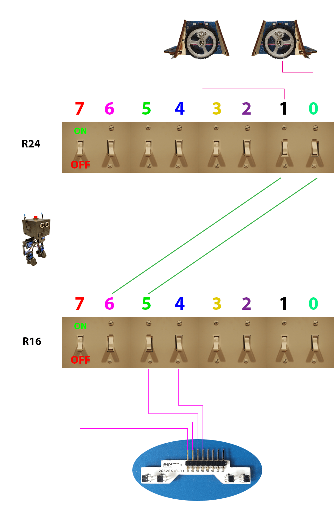
You already saved PINF to r16 using in, so now let’s wire switches 6 and 5 to the left motor and the right motor.
We can’t wire them directly, but we can use the “T-bit”. For fun, I am going to call it the “T-bot” for this class.
You can make the T-bot copy just one switch using bst
Here is an example of the T-bot copying switch 6 in r16 using:
bst r16, 6
Then, we can make the T-bot put that switch it just copied somewhere else using bld
Here is an example of the T-bot placing the switch it copied from r16 into switch 1 of r24 using:
bld r24, 1
See how that works? That’s actually exactly what we needed to do for our line following code. So, now that you know how bst and bld work, let’s add those two lines to our code!
Ok, now it’s finally your turn again! Take your time to figure out these next two steps.
Step 4: Add a line of code to make the T-bot copy switch 5 in r16
Step 5: Add a line of code to make the T-bot place the switch it just copied into switch 0 in r24
Remember the bst and bld instructions you just learned. See the examples above for help!
Before our robot can follow a line, there are two more things left to do.
First, we need to set up the motors and send r24 to them. To save some time, I have done this for you this time.
Step 6: Add this line to your code to call my code that sends r24 to the motors:
call WriteToMotors
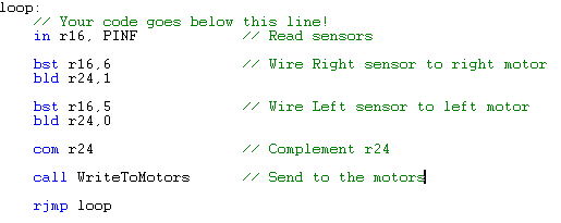
Here is what we have now:
You could test your code right now, but there will be one problem.
If you look at the picture above, if the sensors say yes! there is a black line nearby, and turn their switch on, then, because we wired them to the motors, the motors will turn on.
What we want is the motors to always be on, and then turn off when the sensors say yes! I see a black line.
The solution is to flip all of the switches in r24. Programmers use a smarty-pants word for flip: complement.
To complement a register, type:
com (and then the register name)
Step 7: Add one line of code before “call WriteToMotors” to complement r24
Step 8: Hit the assemble button, plug in the USB cord and use auto-upload to upload your code again. Let’s see if it works!
Click here if you want to go back to lab 1 instructions on how to assemble and upload.
Have some fun drawing lines and letting your robot follow them. The lines need to be black-on-white.
// video coming soon 🙂

