Pathfinder Chassis Spring 2019
Mechanical Design Changes
Author: Christopher Fingers (Design and Manufacturing)
Approval: Alexandrea Jackson (Project Manager)
Table of Contents
Introduction
The current iteration of the Pathfinder Chassis is the same model as previous generations, however there were some additions to improve the functionality of the bot. The design of the bot can be explained in Generation 5’s Final Pathfinder Design blog post.
Mechanical Improvements
Grommets
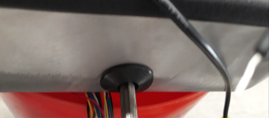
Figure 1: Installed Grommet
The grommets are installed to prevent dust damage from entering the side port area where the differential gear box connects with the main wheels. These grommets are .375 in bore dimension, 1 inch for the inner diameter, 1 ¼ inch for the outside dimension and ⅛ inch in thickness. With the differential bar not being completely centered with the cut out hole, the grommets had to be inserted forcefully.
Thrust Ball Bearings
Previous semesters utilized standard one direction bearings that acted simply as washers. With thrust ball bearings, the rotation is on both sides of the bearings for easier rotation. The bore diameter is 10 mm and the outer diameter is 26 mm. Previously 4 bearings were installed with 2 on each side, however this is unnecessary. The only location for the bearing should be where the two metal parts are spinning in contact.
Mechanical Stop
Rubber stoppers were installed on the front and side of each other metal legs that are near the rocker portion of the rocker bogie system. This is to make it so the rocker does not end up flipping the wheels when it hits an object it cannot traverse over. The idea to use plastic stoppers instead of a metal bar is to prevent metal on metal contact. For future generations, it is recommended to improve this design.
There was a metal stop that was installed underneath the Pathfinder, however this ended up being removed. The metal stop was not able to perform as intended.
SolidWorks Improvements
Improvements to the Solidworks design includes adding nuts and screws to be able to perform a stress test. This semester we added the PCB changes in the solid works design as well as the pan and tilt. It is recommended to perform a stress test with the new body to confirm weak points which may need to be addressed. It is also good to point out that a new design may be needed for the Rocker Bogie System as the current design has issues dealing with balance and climbing over stairs.
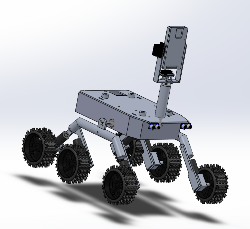
Figure 2: Fully Assembled Chassis Body

Figure 3: Chassis Body
Future Changes
Professor Hill does not like the current set up for the mechanical stop and wishes for them to be changed to something more aesthetically pleasing. As per the previous semesters, there are still some dust protection and water protection properties that need to be included. Dust jackets for the PCBs, drain plug for the bottom of the bot, and spring for the wheels of the chassis. A necessary look for future projects is to perform a stress test on the individual joints and body of the Chassis. The legs of the Chassis that connects the wheels to the differential were found to be backwards. The rocker should be at the tail end of the Pathfinder, but it was discovered to be the wrong way. The legs of the Chassis might need a redesign. The current design of the chassis legs work great on smaller robots, however with the the Pathfinder’s size this design makes it impossible to travel up the stairs needed to be passed on the course. The problem is that while trying to traverse over the stairs, the front and back wheels end up stretching and losing grip with the ground. Either a more complex design for the rocker bogie is required or hinges on any of the angled parts of the aluminum tubing could fix this problem. More research is needed for this.
Conclusion
There are many future items that can be done and implemented in future generations. Our generation wanted to focus on the functionality of Pathfinder versus the mechanical design. It is recommended to begin research on Rocker Bogie System to determine whether the current design is implemented correctly as there may be a few design changes needed in this area.