Proposal Bot/Spring/2020
Mechanical Blog Post- early issues
Author: Tyler Galgas
Introduction
Like any journey, Proposal Bot was met initially with a few bumps in the road. Brand new in design, not only could it move omnidirectionally but Proposal Bot would be the first writing robot as well. Here lies what was discovered upon the iterations of Proposal Bot.
Mechanical Issues
First illustration design flaws:
- Upon initial review of the 3-d model, we determined the pieces were too long to fit the sides on top of the bottom, and that the holes weren’t aligned which in turn meant the motors weren’t aligned.
- In the original design, the pieces were supposed to fit on top of the bottom piece. This could have been what was causing issues with the strength of our box; the box itself was not sturdy enough to hold the weight of the motors without bowing.
Problems with acrylic
- If a sturdier material than acrylic was used, the movement would not be compromised. The box can not hold the weight of the motors which is causing it to cave in. The holes themselves have become slightly shifted which throws off the symmetry. Without symmetry, the movement will be out of sync with what the code is telling it to do. Even if just slightly, since our robot is a writing robot, precision is everything. If we had access, we would reprint with a sturdier option or rebuild from wood.
Traction issue on rollers
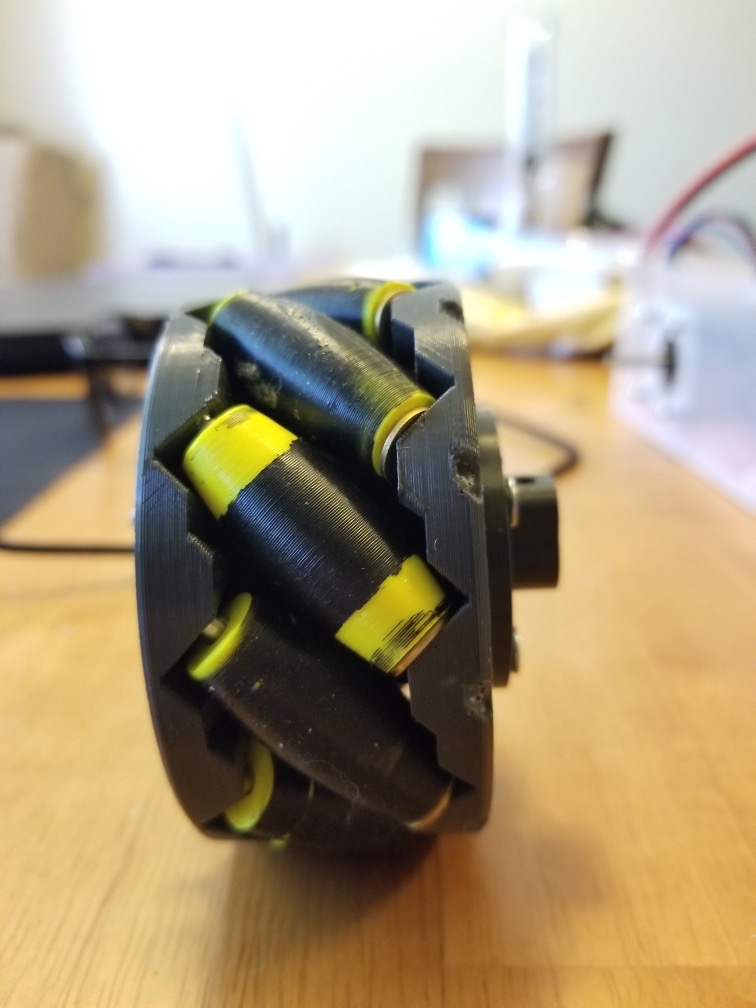
- The movement of our v1 proposal bot was not ideal. Part of this was due to the traction on the rollers being poor. With no grip, the slick plastic couldn’t properly navigate the even slicker surface. To combat this, we dipped the wheels in Plasti Dip. Fully coated caused issues with the wheel now being too thick for the wheel well. However with the dip only around the center of the wheel, an improvement was noticed.
Rod size issue
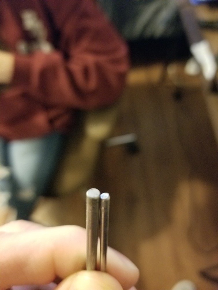
- The rods used in the wheels in the first construction of our box were a size slightly too thin, as the exact size wasn’t able to be tracked down in time for the v1 demo. This caused the wheels to move too much out of place which led to a wonky performance. The correct rods were acquired and the old ones were replaced which seemed to help with proper movement.
Videos
Video
Testing forward movement in V1
Testing side movement in V1
Mechanical Solutions
For the wheels, aiding with a rubber coat to provide more traction and fixing the rod size helped the robot move in a more controlled fashion. Tests were still inconclusive since the box and frame needed to be rebuilt in order to see full effectiveness of this solution.
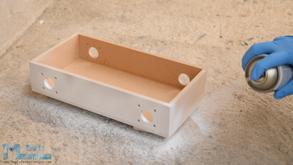
On the frame, one solution would be to use a thicker frame. Something like MDF board (medium density fiber board) over acrylic would have allowed for better operation. Not only would the sides and walls have been strengthened to avoid collapsing into itself, but the thickness would allow for screws to be added in addition to the glue.
- When using a build similar to medium density fibreboard, screws can be added as extra support for the glue; note how the pieces fit flush are locked in place and are attached to the base in the reference project
- When using acrylic, attaching the sides to the base would have not provided support, so a T-type bond was utilized.
- In doing so, the frame can not hold the weight of the motors which is causing it to cave in. The holes themselves have become slightly shifted which throws off the symmetry.
- With proper support, this would not be an issue
Conclusion
As the project presented it’s challenges, steps were made to meet them. A new build was no longer possible due to constraints outside our control, so to speak on the accuracy of the presented solutions is would be ignorant. That being said, with a sturdier frame, I see Proposal Bot moving a lot more controlled.


