This template is saved under “General Blog Post Template”
1st Generation MicroSpot F’19
MicroSpot Circuit and PCB Design
By: Roshandra Scott
Introduction
MicoSpot uses a custom PCB OLED shield which display’s different street signs. This custom PCB shield will also have the shaft encoders and hall effect sensors connected on top of the shield. MicroSpot’s PCB will also be compatible with the 3DoT board.
Bread Boarding
The first iteration of the custom PCB did not include the shaft encoders or the hall effect sensors, because we were just working off the breadboard we had created using the Arduino every. The Arduino every runs on 3.3V, which is the same amount of voltage used for the 3DoT board. Although, Microspot original leg design was based off biped barbEE, we did not use their PCB as a guidance to how we should create ours. Both the biped babrEE and MicroSpot have different missions they had to accomplished so we felt that their PCB would not help when creating our custom shield. You can see the bread boarding on Microspots final blog post.
Designing in Eagle
First iteration: PCB Board and Schematic
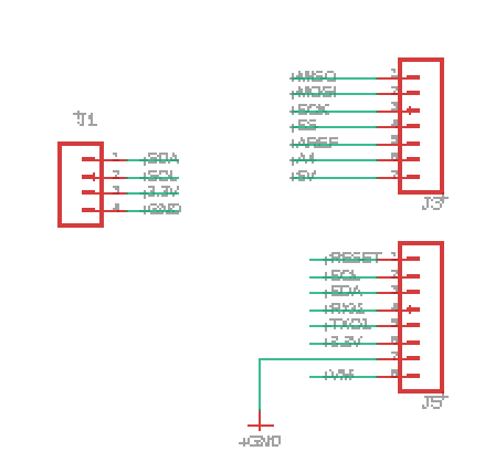
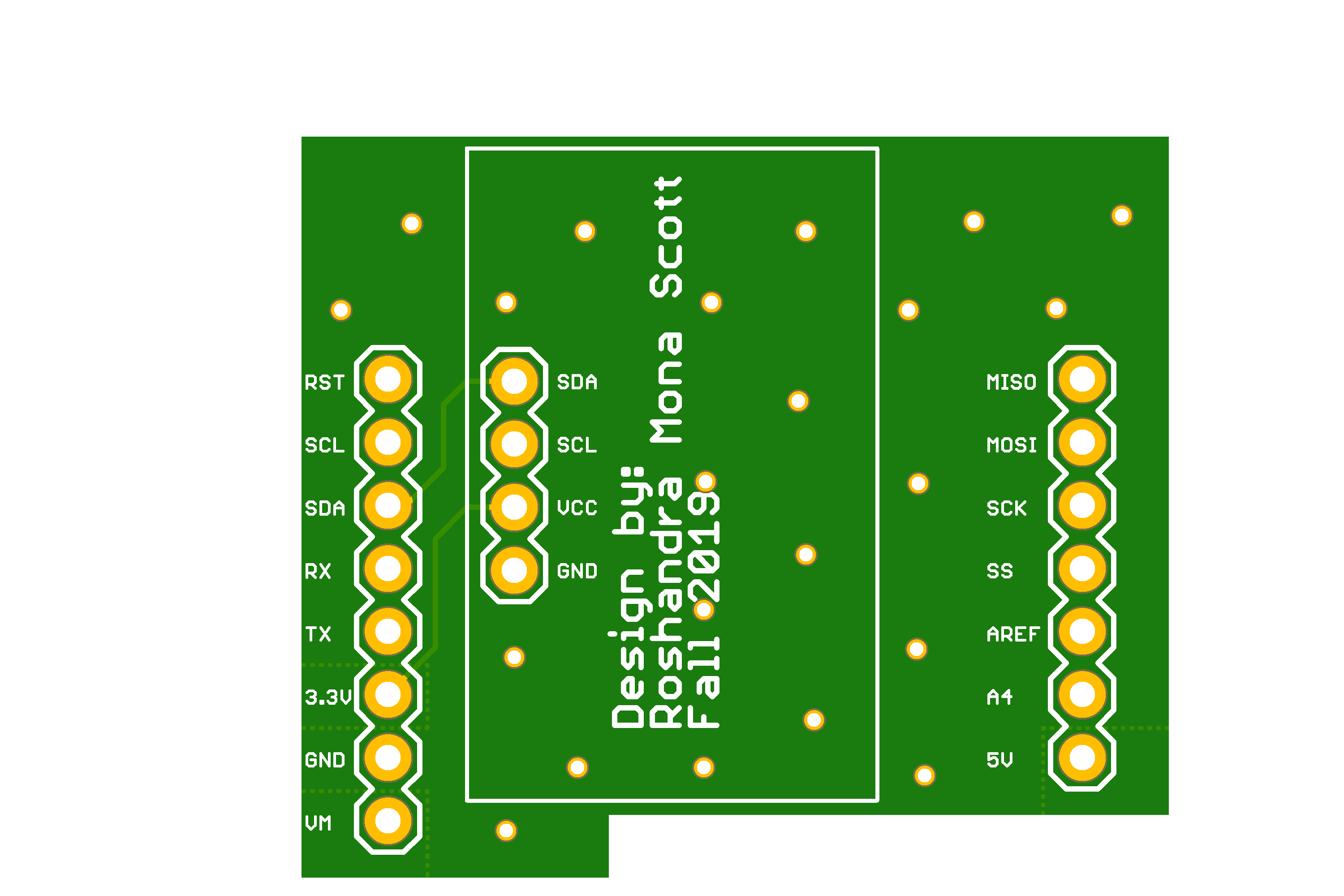
Now that we know the breadboard is working, I started to design and build the custom PCB as seen on the breadboard. This design was simple so using Arxterra’s Eagle guide I was able to complete my design. I need all the pins to fit directly on top of the 3DoT and for my OLED to sit right underneath, the I2C OLED needs to be connected to SCL, SDA, VCC(3.3V) and GND. The errors that were encountered with this iteration is the encoders and hall effect sensors are missing. Also, to make it more of a fully custom design the 30 pin part needs to be added to the schematic and connected properly. This is a shield with the I2C OLED being able to be placed directly on top, which is not what is wanted.
Body 2 Subsection (If needed)
Final iteration: PCB and Schematic
This last iteration of MicroSpot custom PCB took several different iterations, to add all the iterations to this post you will be read for a long time.
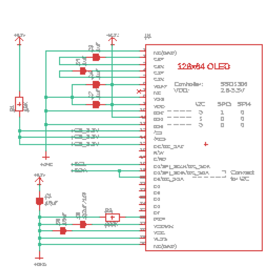
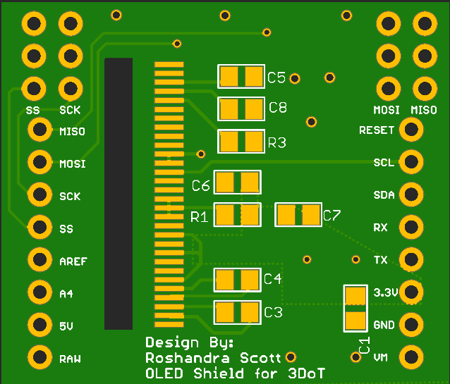
To start, I created my 30 pin part that was needed for the ribbon cable of the OLED display by itself. Creating this part was not the only thing need, you had to make sure it was placed in your eagle library that way, you can use it. If you create a part and do not add it to your eagle library you will not able to use that part. Now, that I have my 30 pin part created I had to use this website https://learn.adafruit.com/monochrome-oled-breakouts/downloads to make sure all my connection to the 30 pin ribbon were correctly routed, and all other components where placed in the correct place. Since, MicroSpot uses shaft encoders and hall effect sensors, which were not breadboarded I decided to create a table to make sure those pins where placed properly on the custom shield. Once all of those main things were all created and complete, I can start connected the wires on the schematic. Eagle CAD is great because when you connect the wires on the schematic or even just have the wires that need to connect together with the same name, when going to the board it uses air wires as a connection. I have connected all air wires and sent it for approval and sent out for fabrication.
| Pin Names | Connections |
| MISO | Left Hall Effect Sensor |
| MOSI | Left Shaft Encoder |
| SCK | Right Hall Effect Sensor |
| SS | Right Shaft Encoder |
Table 1: encoders and sensors
Conclusion
In conculison, I received my PCB fabricated and placed all the components correctly on the board. When trying to plug it into the 3DoT and run the code the screen did not display anything. but I was more than sure it was receiving power from the 3DoT. My thoughts for the screen not displaying anything could be because its a different type of screen and with the I2C library it is very particular on what type of I2C it wants to display on. Since, the semester ended I was unable to test my theory to see if I was correct. Good luck, I hope this helps.
References/Resources
- https://learn.adafruit.com/monochrome-oled-breakouts/downloads
- https://www.youtube.com/watch?v=cURh2-dTuI0
- https://www.instructables.com/id/Monochrome-096-i2c-OLED-display-with-arduino-SSD13/
- https://randomnerdtutorials.com/guide-for-oled-display-with-arduino/
- https://www.arxterra.com/getting-started/electronics-and-control-resources/#part15
- https://www.arxterra.com/getting-started/
- https://www.arxterra.com/programming-your-robot-custom-telemetry/
- https://www.youtube.com/watch?v=U36_et5UnxI
- https://www.robot-electronics.co.uk/i2c-tutorial
- https://i2c.info/i2c-bus-specification


