MicroSpot Gen 1 Summary Blog Post
Author/s: Kyle Gee, Roshandra Scott, Surdeep Singh, and Ryan Vega
Editor: Adam K Cardenas
Approval:
Table of Contents
Executive Summary
By Ryan Vega:
This project is focused on creating an evolution of a previous project entitled Biped barbEE. Our focus was to create a toy that could stand while bearing weight, walk, recognize and respond to common traffic signs; it can even show the user proof of recognition by displaying symbols on its personal LED. Rather than a “Barbie” (we assume the name barbEE alludes to), we have instead crafted a small dog-like toy-companion in homage to the robot designed by former MIT students (now Boston Dynamics), Spot (and now also SpotMini). MicroSpot is Bluetooth controlled via the ArxRobot app developed for both Android or iOS phones.
Program and Project Objectives
Program Objectives
By Surdeep Singh and Ryan Vega:
MicroSpot is both an experiment and a project intended to study the limits of an experimental leg artifice created by Mark Plecnik during his career at UCI. The attraction to this leg design is the ability to have an array of legs powered by a minimal number of actuators, in our case a singular motor per each same-side set of legs, via a transference of motion through pliable and resilient pantographs (compliant design). The legs are light, and low profile, allowing for practical applications to resolve situations in small spaces. While the device itself could serve a more useful purpose than a toy, through exploring via play we intend to discover obscure and innovative applications for visual recognition from an perspective. Its design should allow it to move incredibly power efficiently while having reserve load bearing strength and reserve power for extended peripheral possibilities. Its integration with a controller-app produced both for iOS and Android, based on open sourced code, allows for future peers to easily access, modify, build upon, or retrofit our design for alternate purposes.
Project Objectives
by Kyle Gee and Ryan Vega:
MicroSpot is dog-like rover drone in homage to Boston Dynamics’ Spot, the Jansen’s linkage, and a variety of cool historical devices sent into space to foreign planets. MicroSpot is a branch-off from the previous semesters’ Bipedal Motor design. Microspot specifically features a reiteration of the leg design implemented by the Barbee of the Spring 2019 semester, which based on the Compliant Three-Leg Module Kinematic Design of the Robotics and Automation Laboratory at University of California, Irvine (specifically credited to Mark Plecnik, Veronica Swanson and J. Michael McCarthy). This toy will be smaller than Spot, with legs produced of a stronger base material than the original design, featuring spacers, and will be more affordable to produce. The ability for MicroSpot to be controlled via the Arxterra app over Bluetooth will allow for versatile and simplistic (as it is pre-developed) usability allowing kids to enjoy their robot companion without the interference of cords, and the elegance of a controller that can be found in any parent’s pocket.
Mission Profile
By Roshandra Scott and Ryan Vega:
The prototype toy is targeted to young kids so that they can have their very own robotic pet. Kids can control MicroSpot via Bluetooth using the Arxterra app. MicroSpot will be able to walk and read street signs through the use of a small internal computer (Raspberry Pi) and will display a sort of proof of recognition on its personal OLED Display. The sturdy design of the toy gives kids the ability to use it not only in the house, but also outside in real play environments.
Our mission by the end of the semester is to motivate MicroSpot, an experimental legged rover, over a small amount terrain while demonstrating visual recognition, power efficiency, and peripheral application possibilities. We believe MicroSpot is the beginnings of a very interesting future.
Project Features
By Ryan Vega:
MicroSpot features a 5000 mAH battery, two Plecnik designed 3-legged walking modules (leg sets), a 720p camera, a 3DoT (predesigned micro-controller development board featuring Bluetooth for pairability), a PCB based LED, a Raspberry Pi (single board computer), and a custom SolidWorks designed 3D printed chassis with dedicated snug housing for all of the individual components.
Requirements
The following is a prescribed list of standards and constraints.
Engineering Standards and Constraints
By Kyle Gee and Ryan Vega:
Applicable Engineering Standards
1.) MicroSpot shall comply with IEEE 29148-2018 – ISO/IEC/IEEE Approved Draft International Standard – Systems and Software Engineering — Life Cycle Processes –Requirements Engineering.
2.) MicroSpot shall comply with NASA/SP-2007-6105 Rev1 – Systems Engineering Handbook
3.) MicroSpot shall comply with Bluetooth Special Interest Group (SIG) Standard (supersedes IEEE 802.15.1)
4.) MicroSpot shall comply with C++ standard (ISO/IEC 14882:1998)
5.) MicroSpot shall comply with NXP Semiconductor, UM10204, I2C-bus specification and user operation man liscence
6.) MicroSpot shall comply with ATmega16U4/ATmega32U4, 8-bit Microcontroller with 16/32K bytes of ISP Flash and USB Controller datasheet section datasheet, Section 18, USART.
Environmental, Health, and Safety (EH&S) Standards
1.) MicroSpot shall comply with CSULB COE Lab Safety
2.) MicroSpot shall comply with CSULB Environmental Health & Safety (EH&S)
3.) MicroSpot shall comply with IEEE National Electrical Safety Code (NESC)
4.) MicroSpot shall comply with NCEES Fundamental Handbook (FE) Reference Handbook
5.) MicroSpot shall comply with ASTM F963-17, The Standard Consumer Safety Specification for Toy Safety (which is a comprehensive standard, or list of regulations, addressing numerous hazards found with the use of toys).
- Manufacturers of children’s products must certify compliance with applicable federal safety requirements in a Children’s Product Certificate (CPC) via verification by a third party CPSC-Accepted Laboratory.
- All children’s products must include permanent tracking information on the product and its packaging to the utmost possible extent.
- All children’s products must feature hazard warnings for obvious and foreseeable hazards.
- All children’s products unfit for specific age groups must feature age indicators/ ranges as dictated necessary by a CSPC verified third-party.
- All accessible components of a children’s product must be verified for compliance with the lead content limit of 100 parts per million. 16 CFR § 1500.88 – Exemptions from lead limits for electronic devices:
- Section 101(b)(2) of the CPSIA further provides that the lead limits do not apply to component parts of a product that are not accessible to a child. This section specifies that a component part is not accessible if it is not physically exposed by reason of a sealed covering or casing and does not become physically exposed through reasonably foreseeable use and abuse of the product including swallowing, mouthing, breaking, or other children’s activities, and the aging of the product, as determined by the Commission.
7.) MicroSpot shall comply with NFPA 70E Standard for Electrical Safety Requirements for Employee Workspaces
8.) MicroSpot shall comply with CSULB PPFM Environmental Compliance Electronic Waste Handling and Disposal Procedures. This lays out the procedures and policies regarding hazardous waste and E-waste. We shall follow these guidelines for the proper disposal of batteries, or any other electronics that can cause harm to health or the environment.
Constraints
1.) Utilizes the Arxterra App
2.) Utilizes a 3DoT
3.) Utilizes a personally developed PCB
4.) Meet completion by the dead line 12/17
5.) The value of expenditures must stay below $1000 dollars
6.) Be 3D printed
Program Level 1 Requirements
By Kyle Gee:
L1-1- MicroSpot will stand without external aid
L-1-2- MicroSpot will use a camera to recognize predefined signs
L1-3- MicroSpot shall walk forward upon user instruction
L1-4- MicroSpot shall be controlled through the ArxRobot app
L1-5- MicroSpot will use a custom PCB for connecting components
L1-6- Chassis will be 3D printed
L1-7 -MicroSpot should turn
L1-8- MicroSpot shall use the 3DoT board to control the motors
L1-9- MicroSpot shall not cost more than $350
L1-10- MicroSpot will be completed on December 17th, 2019
System/Subsystem/Specifications Level 2 Requirements
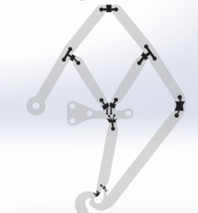
L2-1-1-MicroSpot’s leg design will be a 3D printed adaptation of University of California, Irvine’s Mark Plecnik’s polypropylene laser-cut model
L2-1-2-MicroSpot will have at least 3 legs on the ground to establish stability while standing
L2-2-1- MicroSpot shall use a raspberry pi to do the recognition software
L2-2-2 -The Raspberry pi shall send the detected results to the 3DoT
L2-2-3- MicroSpot should stop when it recognises the Stop sign
L2-2-4-MicroSpot should slow down when it recognizes the Yield sign
L2-2-5-MicroSpot should turn right when it recognizes a right turn sign
L2-2-6-MicroSpot should turn left when it recognizes a left turn sign
L2-2-7 MicroSpot should speed up when it recognizes the speed limit sign
L2-3-1–MicroSpot will have 2 motors to drive the legs
L2-3-2–Motor will operate at 5V provided by the 3DoT
L2-3-3–Motors shall move 180 out of phase
L2-3-4–Hall effect shall be implemented to know the absolute position of the crank/ leg
L2-3-5–Shaft encoder shall be used for relative position of the crank/ legs
L2- 4-1––MicroSpot shall establish Bluetooth connection with the Arxterra App and the user can adjust the speed and motor direction
L2-4-2––User should be able to turn off the detection mode on the app
L2-4-3––User should be able to turn on the detection mode on the app
L2-5-1––Custom PCB shall have an OLED display to show signs detected
L2-6-1––Chassis will house the electronic components
Allocated Requirements / System Resource Reports
Project Report
By Roshandra Scott:
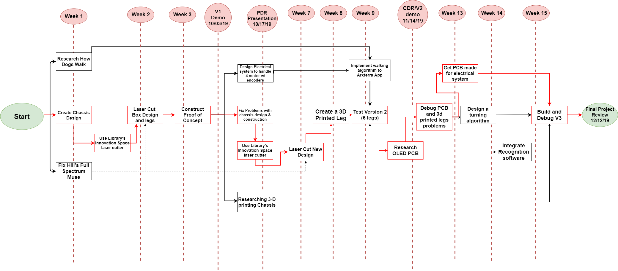
In this section our work is broken down into simplified choreographed charts, in order to simply present workloads, show visually how the workloads were actually divvied out, and what players took what roles. In a similar fashion, our device is then broken down into its variety of components according to subsystem organization.
Lastly, you will also find budget, schedule and burndown enclosed.
Project WBS and PBS
By Kyle Gee:
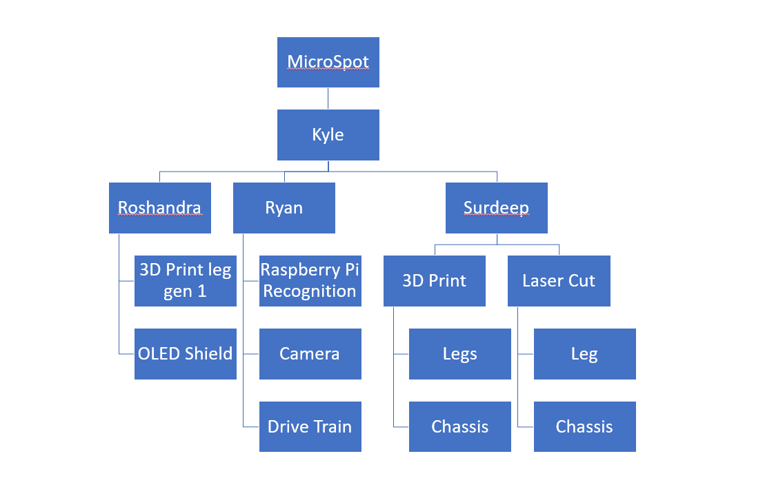
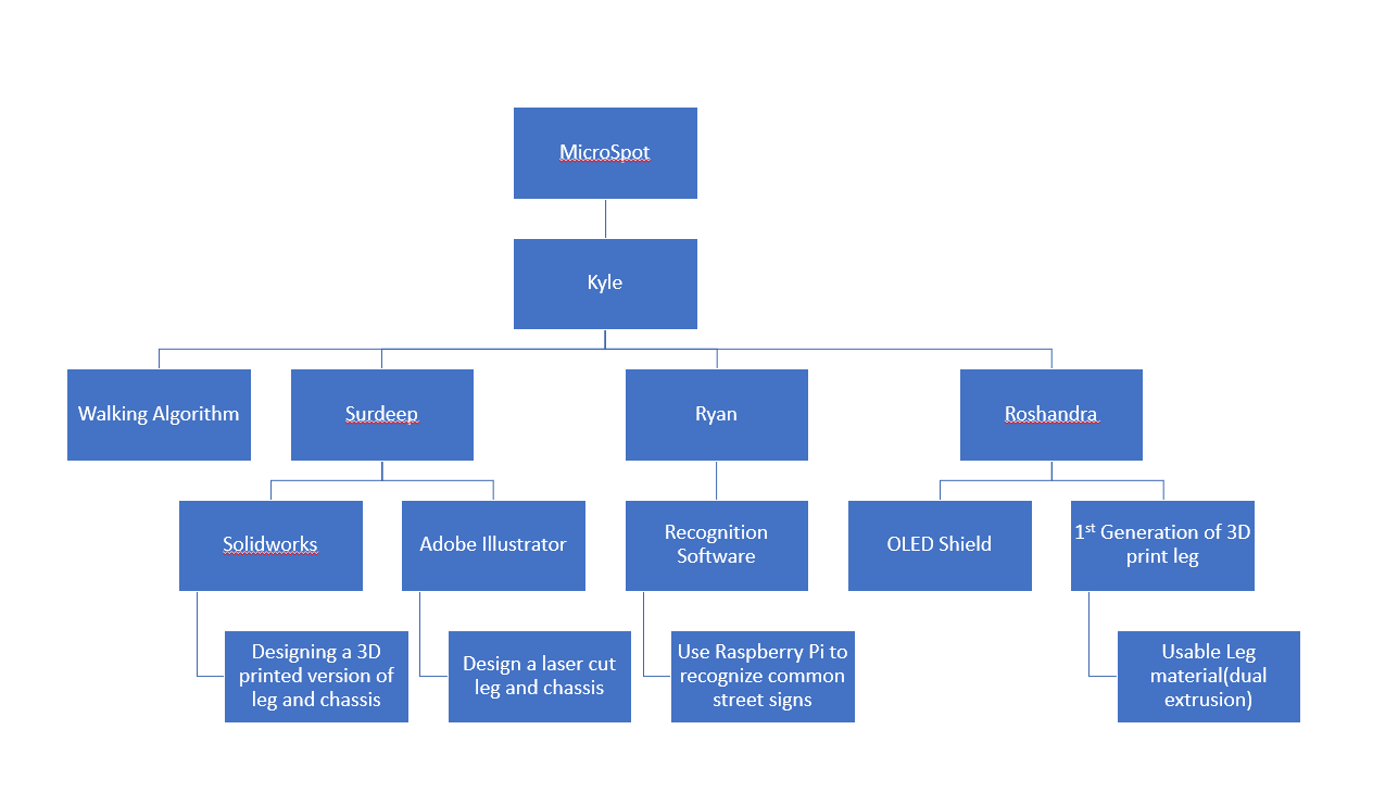
Product breakdown Structure (PBS):
MicroSpot was divided into 3 main subsections: 3D print/laser cut models, custom PCB shield, and camera recognition. I was the project manager, whose task was to oversee the entire project. Surdeep was in charge of designing and submitting 3D printer and laser cut models. Roshandra started as the 3D printed leg designer, but was moved to focus on MicroSpot’s custom PCB. Lastly, Ryan was the one to make sure that electronic components of the design operated, including the 3DoT, the Raspberry Pi’s “computer vision,” and all necessary mass, stress, and power requirements.
Work Breakdown Structure(WBS):
I worked on primarily managing other members and I worked on the walking algorithm for MicroSpot as necessary. MicroSpot’s first iteration of 3D printed legs were drafted by Roshandra who discovered the 2 material-type that could accomplish the 3 complaint leg system. Surdeep used Solidworks and Adobe Illustrator to create models to build the physical prototypes of MicroSpot. Ryan mastered the physical design of the MicroSpot (sending the data to Surdeep) and trained the Raspberry Pi to recognize the common street signs stop, yield, right turn, left turn, and a 60mph speed limit.
Cost
By Surdeep Singh:
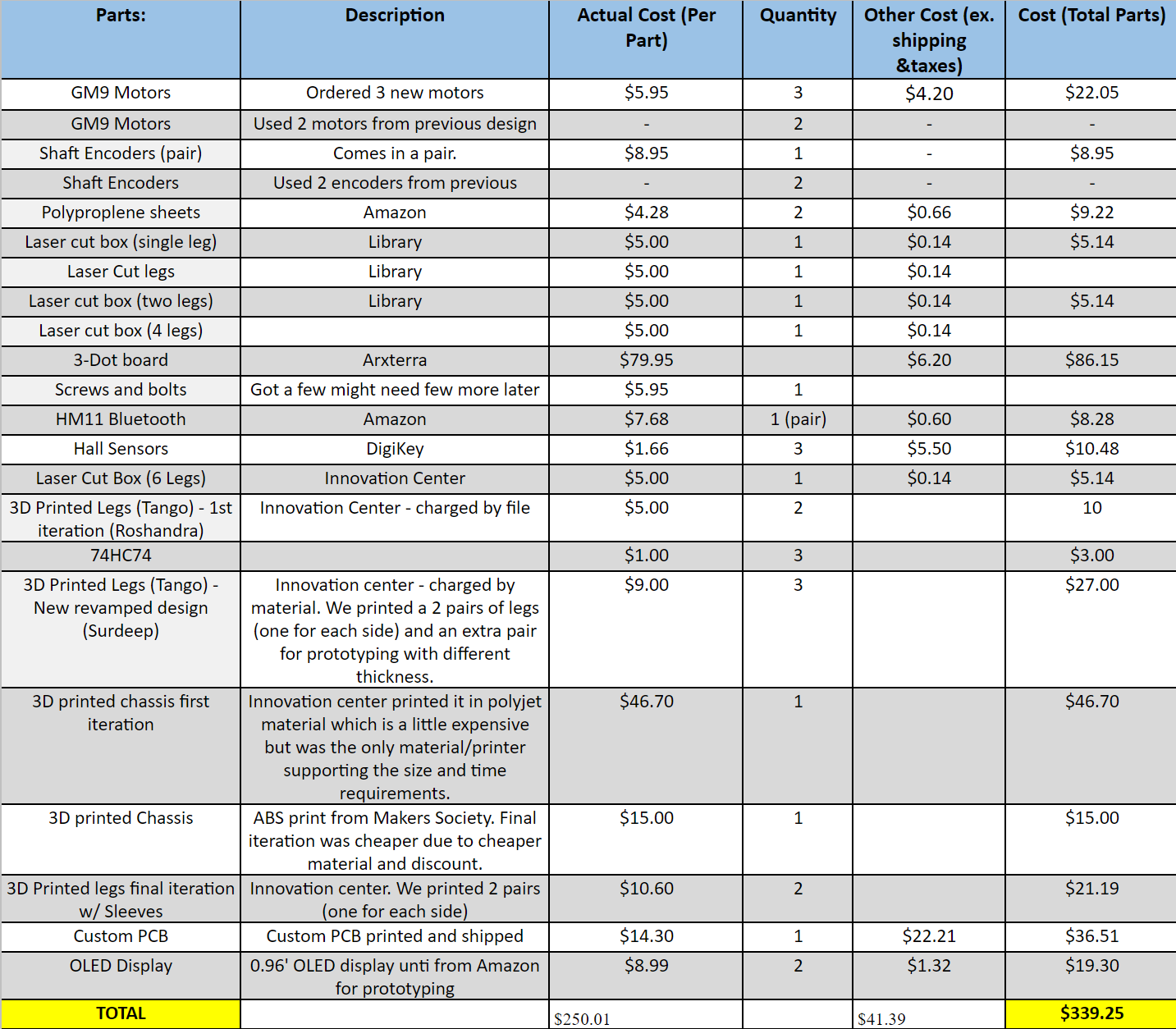
MicroSpot was budgeted for $350. This budget was just for new items that we needed as we did inherit a lot of items from previous semester’s DC motor – BiPed, and from a card shuffler project that was merged with us mid semester. We did not include the staple prices of the 4 3DoT boards, nor did we include the price of the RPi or any of its assets. The budget spreadsheet in the link lists our the items that were acquired in comparison the ones that were purchased. Our biggest cost was the combined cost of the 3D printing of the legs and chassis.
Schedule
Burndown and/or Percent Complete
By Roshandra Scott:
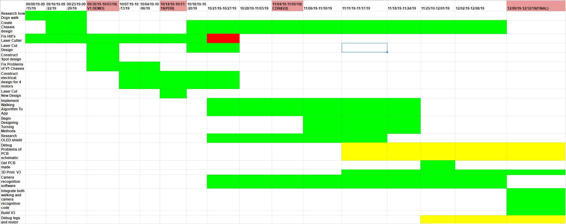
Here is a Link to the Burndown of MicroSpot.
Concept and Preliminary Design
Literature Review
By Surdeep Singh:
The original MicroSpot design was taking the polypropylene leg design from the previous generation DC Motor Bi-Ped project. We reviewed the BiPed using the single leg on each of the chassis as discussed in their blog post. But we did not have a working model with an actual body to hold the legs. BiPed used the UCI design which is a compliant leg that allows for flexion and compression of the leg without breaking the solid material.
In order to understand the best way to implement this design, we researched animal walking mechanisms. We mostly researched walking of 4-legged animals such as dogs since we wanted to use the compliant design to produce a mini-Boston “Spot” dog. Our research on dog walking can be referred to in this blog post . Building off the BiPed we tried to convert it into a 4-legged bot using four motors. Initially we used the laser cutting file from BiPed for the leg design and created 4 legs from polypropylene (PP).
We had a few issues with the 4 legged design as we needed to have a complex code enabling 4 motors to walk in correct phase difference, or else MicroSpot would fail and fall over. Given the fact that the 3DoT provides only 2 motor drivers we also had to research ways to add additional motor drivers to support the additional 2 motors. This complicated our design to a point where meeting deadlines was not feasible.
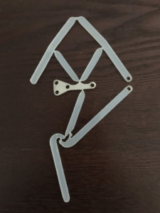
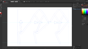
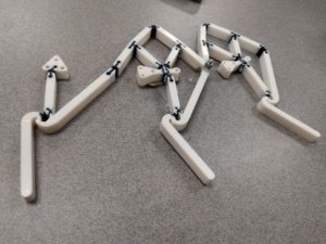
So, we went to the source of the compliant leg design. We then reviewed the original 6 linkages, 3-legged compliant design by Mark Plenik (UCI). Upon studying the design, we decided to utilize the 6 legged crawler design in translation to our MicroSpot, as such a design provided us with a way of making the bot move with only 2 motors and provided standing capability. Since we did not have access to the original design we followed a similar process to our predecessor, barBEE BiPed, and used Adobe Illustrator to create a vector form of the 3 legs exploiting a video screenshot from Mark Plecnik’s design.
We produced a few cuts that were unusable but improved upon the design; then, we realized that polypropylene would limit us due to the amount of power necessary, and the weight that was to be supported. Polypropylene was weak and relatively brittle.
We proceeded to create a 3D print of the legs which would allow us to make them thicker but our issue was the material, since printed material is mostly rigid and doesn’t allow for the kind of bends we needed. We did a lot of material research on specialty 3D printers that can print using dual extrusion. We finally were able to pin down a PolyJet-able material called tango that allowed us to create a design with flexible but enduring joints The initial prototype did not hold the weight, as the joints ended up being too soft.
At this point further research was done to identify a way of making flex-joints softer while retaining the integrity of the leg. We reviewed the original UCI design again to clearly identify moving joints and researched various dual printed flex-joints. Upon avid research we created a prototype that included the soft Tango material to the design (in place of the PP) while keeping the pressure points, that joints tend to be, more rigid. This design was successful in holding up the chassis and even capable of putting up with the stress caused by movement.
Design Innovation
By Ryan Vega:
MicroSpot technically has no predecessor. However, because of the existence of barBee and that some, although not many, of barbEE’s features inspired and educated the design of MicroSpot, it is important to recognize barbEE as a foundation. In most fundamental ways MicroSpot is different from barbEE. For starters, MicroSpot is not 2-legged but 6-legged, comprising two 3-legged pantographic modules (sets of legs). The material of these legs has been changed from the early choice of PP to Tango for reduced flexibility and increased strength. As MicroSpot is no longer bipedal like its compatriot, it now has the ability to carry itself (stand) and even move. MicroSpot is significantly closer to the ground with a lower center of gravity than its compatriot.
MicroSpot runs by a 3DoT and a Raspberry Pi. The 3DoT enables MicroSpot’s two motors and gives MicroSpot the ability to be controlled through its integrated Bluetooth module via the Arxterra app; but MicroSpot, as it can actually move, makes more use of the app’s features than barbEE ever did. MicroSpot also has the ability to artificially identify and respond to several common street signs because of the integration of a Raspberry Pi 3b+ resourced with Open CV; Because, what really makes MicroSpot special are its two peripherals, an RPi camera and a 3DoT-shield OLED display.
Conceptual Design / Proposed Solution
By Kyle Gee:
The first conceptual design was inspired by seeing the Theo Jansen legs that were implemented in many of the BiPed designs prior to the Spring 2019 project barbEE. After getting to play with the previous semester’s laser cut PP legs, we noticed that the legs were very flexible yet still sturdy. We thought to put four legs to the chassis and because that would be a reminiscent of a dog.
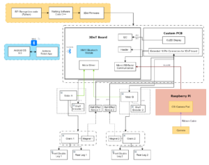
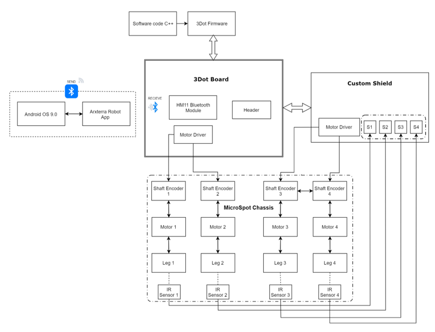
As you can see from the system block diagram above, there are many components and a lot of data coming into the 3DoT board. In order to handle all the data, we would need to integrate another microprocessor to handle the data from the 4 IR, and from the 4 shaft encoders. Another thing we would need to test is the timing to begin initializing the walk cycle for each leg and most likely we would need a PID controller to maintain the timing. Due to time constraints of the class, we had to change how we were going to constuct MicroSpot, and that’s how we came to the current iteration of MicroSpot. From PDR our budget has not changed, it has stayed at $350. Since MicroSpot had acquire a disbanded team we want to try to integrate their past work into ours. Thus, this is how MicroSpot added a Raspberry Pi recognition system. Soon after PDR, we came to realize that using polypropylene for the legs would be too finicky and we changed our leg design to be 3D printed instead of laser cutted.
System Design / Final Design and Results
System Block Diagram
By Surdeep Singh:
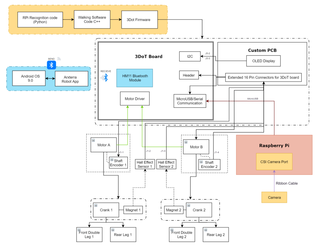
MicroSpot evolved a lot over time and so the system block diagram became more extensive as well. The system started with 4 motors, one controlling each leg using two on board motor drivers and a custom PCB to add additional 2 drivers. We realized that it was an overcomplicated system and will not be sustainable in order to meet the customer deadline. The evolved project plan updated the mechanical leg design to allow for reduction in overall system utilities. The final system has 2 DC motor units, each controlling a pair of legs on each side of the bot. In order to calibrate the legs and control MicroSpot efficiently, each side of the chassis has a hall effect sensor getting magnetic input from the magnet attached to crank. This would provide us absolute leg placement while we also have 1 shaft encoder on each leg to provide us relative position of the leg. The encoders and the hall effect sensors connect to 3DoT using the extended pins on the Custom shield while the motors are connected directly to the motor drivers on the 3DoT. The custom PCB connects directly on top of the 3DoT board and has the OLED integrated on top of the PCB. Bluetooth is another component that is directly on the 3DoT board and allows us to communicate wirelessly with the bot using the Arxterra app. The cable connections are represented as in the system block diagram below. Finally, we have a sign recognition system that uses a Raspberry Pi and Raspberry Pi camera. The camera communicates with the RPi using a ribbon cable connector and the RPi directly communicates with the 3DoT using the Micro USB serial comm port. The RPi is powered using an external battery. All the components such as the 2 motors, Raspberry Pi, RPi camera, the 3DoT board with custom PCB, the hall effect sensors and the external battery are situated inside a 3D printed chassis. The firmware code used for 3DoT is written in C++ and integrates with the code from the RPi written in Python to enable controlling all the features using the 3DoT board.
Interface Definition
By Roshandra Scott:
The interface Matrix display is where everything will be connected to each other. For MicroSpot, we will be connecting the Raspberry Pi to the 3DoT board through the USB connection on Pi. From this the PCB shield will be connected to all 16 pins on the 3DoT board, along with an extra 12 pins for the hall effect sensors and shaft encoders. The motors on MicroSpot are connected to the motor drivers A and B on the 3DoT board, where those will be controlled via bluetooth arxterra app.
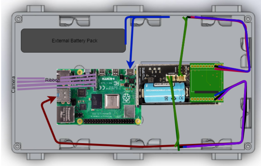
A cable tree is a wiring diagram that shows how each component will be physically connected to MicroSpot. This cable tree picture design is the top view, what will be seen when lifting the lid of MicroSpot. The cables are wired as followed the raspberry pi is connected to an external battery pack, where the 3DoT board is connected to the raspberry pi through the USB. The motors are connected to the motor drivers A and B, all shaft encoders and hall effect sensors will be connected to the PCB shield. The PCB shield is powered by sitting directly on top of the 3DoT board, using 3.3V and GND.
Modeling/Experimental Results
By Surdeep Singh:
Introducing walking stability to MicroSpot required a leg design that allowed for 3 points in contact with ground at all times.
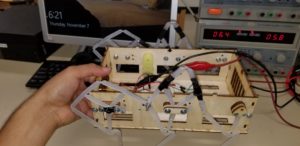
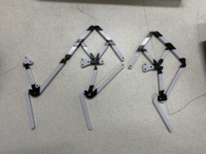
- In order to obtain walk stability we experimented with the 3 leg compliant design using laser cut polypropylene. We added one set of legs on each side of the chassis and ran test with a power supply.
MicroSpot V2 with Polypropylene legs video
- While the polypropylene design provided us with proof of concept we still had a few outstanding issues such as the breaking of leg joints due to thinness. This prompted us to adopt 3D printing for legs.
- The first 3D print leg design was an experiment with the material that could provide 2 materials in one print allowing us to maintain the compliance feature. Polyjet (tango) was used for the first print and while it failed to produce a functional leg, it did present with a confirmation that the material can be used to print a functional leg with better design.
· We then sketched a few different design options for the next prototype and proceeded with the following design where it only covered the areas of the leg that truly needed to bend or stretch and left everything else in as solid. This model did turn out to be a winner and became the base of our final iterations of leg design for MicroSpot.
Mission Command and Control
By Kyle Gee:
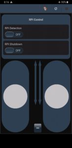
Move(0x01) – The user will be able to control each motor with the two sliders on the App. By using the sliders the user can manually adjust the speed.
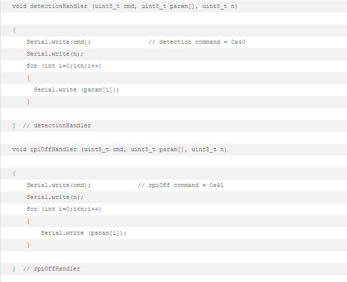
Raspberry Pi Detection (0x40) – The user can turn on and off the Raspberry Pi detection system, more specifically it turn on and off the camera on the Raspberry Pi. By turning off the detection system, the user can manually control MicroSpot without any interferrance if the camera picked up any of the signs that had overriding command.
Raspberry Pi Shutoff (0x41) – The user can shutdown the Raspberry Pi if not in use, this will help save the battery life.
Electronic Design
PCB Design
By Roshandra Scott:
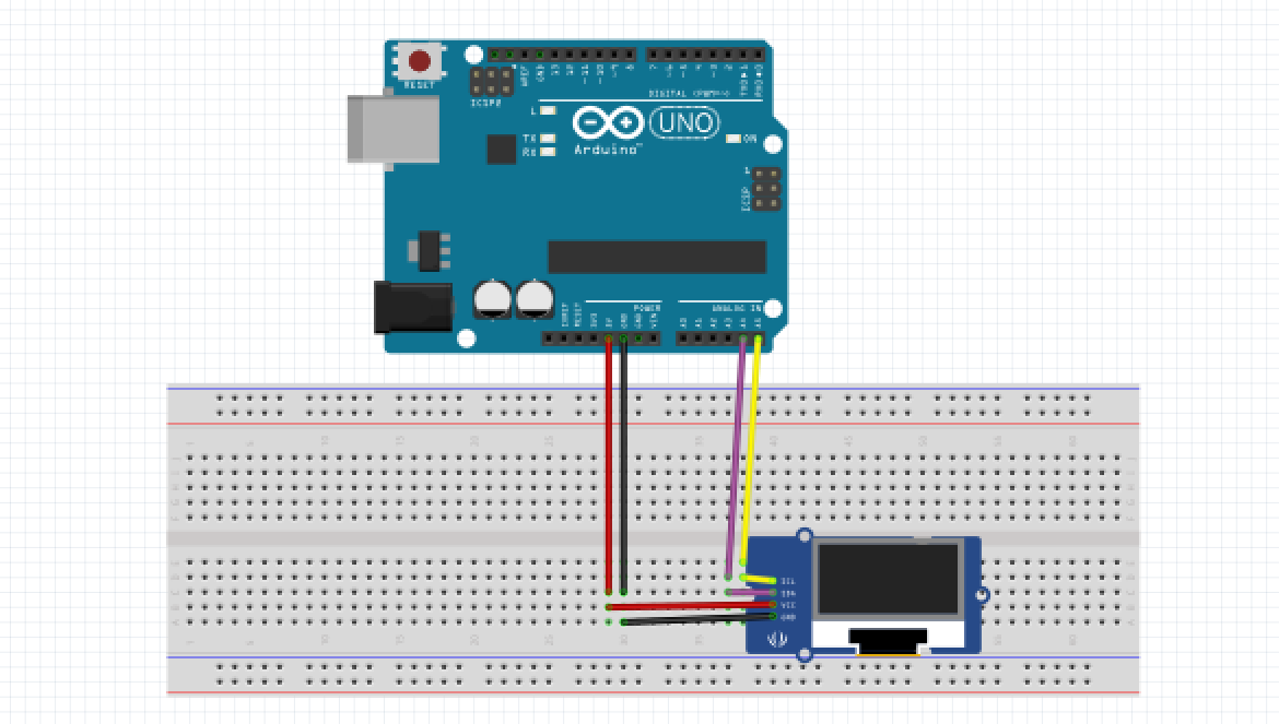
This PCB design for MicroSpot uses an OLED to be able to display street signs. The first test was using an Arduino Uno running on 5V.
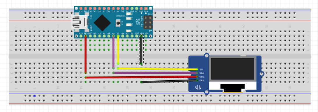
Now that we are confident that the OLED works using 5V, we moved to an Arduino Nano every which only runs on 3.3v because that is the voltage needed by the 3DoT board.
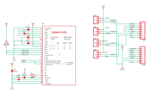
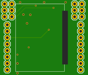
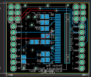
Finally, everything works and it runs on 3.3v just how we want. We move forward with the designing of the PCB using Eagle CAD, keeping in mind that hall effect sensors and shaft encoders will be used. Originally, we were thinking we would be able to get rid of some pins on the 3DoT board but does not work. The OLED is a very complicated PCB within itself, and trying to only get the part for the 30 pin ribbon connector in Eagle CAD was not possible. The first thing we needed to do was create the 30 pin ribbon connector, without this connection we will not be able to display a screen onto the 3DoT OLED Shield.
Firmware
Raspberry Pi Image Detection Software
By Ryan Vega:
https://www.arxterra.com/?p=153081&=true
*Pleaselink to my personal blog post here which pertains to my RPi image detection software.
3DoT Firmware:(PID 180o Move Control)
By Kyle Gee and Ryan Vega:
To preface this section, it is important to note that a majority of the code utilizes Brandon Nguyen’s code for the Hexy as a base. I translated the code to work with a 3DoT board because the original code was for an Arduino Nano. I also set up an interrupt-service routine (ISR) for the code.
// Pinouts for ATmega32U4
// Motor Driver Definitions
#define AIN1 12
#define AIN2 4
#define PWMA 6
#define BIN1 9
#define BIN2 5
#define PWMB 10
#define STBY 8

// Shaft Encoder Definitions (These need external interrupt pins)
#define outAR 16 // Right Motor Output
#define outAL 17 // Left Motor Output

// Gear Position Sensor
#define phaR 15 // Right Gear
#define phaL 14 // Left Gear works

uint8_t gearLeft, gearRight, pastGearLeft, pastGearRight;
uint8_t setupTickL, setupTickR;


// Phase Variables
float totalTicks= 720;
float phaseRight, phaseLeft, phaseError;

int rightPWM = 180;
int leftPWM = 180; //original 180
int maxRightPWM = 200;
int maxLeftPWM = 200;
int minRightPWM = 160;
int minLeftPWM = 160;

volatile long ticksR, ticksL;
volatile uint8_t pinLast = 0;

// --------------- PID Controller ---------------
double SetpointR, InputR, OutputR;
//Specify the links and initial tuning parameters | P,I,D = 2,6,1
PID myPID_R(&InputR, &OutputR, &SetpointR, 2, 6, 1, DIRECT);

//uint8_t dpMaxSteps = 128; //remember even thought the the digital pot has 128 steps it looses one on either end (usually cant go all the way to last tick)
//int maxRangeOhms = 100000; //this is a 5K potentiometer
//MCP4017 i2cDP(MCP4017ADDRESS, dpMaxSteps, maxRangeOhms);

//ISR
ISR(PCINT0_vect){
uint8_t pinStatus= PINB & (_BV(PB2)|_BV(PB0));
uint8_t pinChange= pinLast^pinStatus;
pinLast=pinStatus;
if(pinChange==_BV(PB0))ticksR++;
if(pinChange==_BV(PB2))ticksL++;

}
Functions used to setup 180o out of phase and to keep in phase:
void countTicksR() {
ticksR++;
}

void countTicksL() {
ticksL++;
}

void Init3DoT() {
// Motor Driver = OUTPUT

pinMode(AIN1,OUTPUT);
pinMode(AIN2,OUTPUT);
pinMode(PWMA,OUTPUT);
pinMode(STBY,OUTPUT);
pinMode(BIN1,OUTPUT);
pinMode(BIN2,OUTPUT);
pinMode(PWMB,OUTPUT);
pinMode(BLINK, OUTPUT);
/*
// Ultrasonic Sensors
pinMode(trigPin, OUTPUT);
pinMode(echoPin, INPUT);
*/
//Absolute phase encoder
pinMode(phaR, INPUT_PULLUP);
pinMode(phaL, INPUT_PULLUP);

Serial.begin(9600);
}

void left_forward(){
digitalWrite(AIN1,LOW);
digitalWrite(AIN2,HIGH);
analogWrite(PWMA,leftPWM);
digitalWrite(STBY,HIGH);
}

void left_stop(){
digitalWrite(AIN1,LOW);
digitalWrite(AIN2,LOW);
analogWrite(PWMA,leftPWM);
digitalWrite(STBY,HIGH); //gearRight = digitalRead(phaR);
//Serial.println(phaR);
}
void right_forward(){
digitalWrite(BIN1,LOW);
digitalWrite(BIN2,HIGH);
analogWrite(PWMB,rightPWM);
digitalWrite(STBY,HIGH);
}

void right_stop(){
digitalWrite(BIN1,LOW);
digitalWrite(BIN2,LOW);
analogWrite(PWMB,rightPWM);
digitalWrite(STBY,HIGH);

}
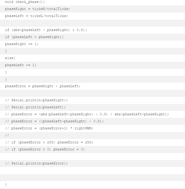
In the beginning of the code are just the definitions and the libraries used for the 180o out of phase motors. Before the setup, I create the process that will be done when the ISR is called. In the ISR, I take the current pin readings and it to PB2 and PB0 this clears the other values leaving just the information at the 2 pins. Then it does an exclusive, or to see which pin actually changed and sets the new pin’s last status. Lastly it does 2 “if” statements to determine which tick variable to increment. Then in the setup, I enSoftable the pins for pin-change interrupts, then locally enable interrupts, and lastly globally enable the interrupt.
Within setup it moves the left motor till it receives a reading from the hall effect sensor. Once the left motor has stopped, it then moves the right motor until it achieves the 180o out-of-phase at the start. In the loop, the code keeps checking the amount of times the shaft encoders tick, which is held by the left and right tick variable that is counted in the ISR. Based on the readind it will make the appropriate adjustments to get the motor back aligned.
Recognition Software:
U8GLIB_SSD1306_128X64 u8g(U8G_I2C_OPT_NO_ACK); // Display which does not send AC

Adafruit_SSD1306 display(SCREEN_WIDTH, SCREEN_HEIGHT, &Wire, -1);

//////////// end of Roshandra code
//////////////  Ryan's modified ArxRobot_Telecom code
#define DETECTION    0x40 // Sets the hex value that the ArxRobot APP will send for the Detection custom command
#define RPiOFF       0x41 // Sets the hex value that the ArxRobot APP will send for the RPiOFF custom command
#define SCREEN_WIDTH 128  // OLED display width, in pixels
#define SCREEN_HEIGHT 64  // OLED display height, in pixels
const uint8_t CMD_LIST_SIZE = 2;    // we are adding 2 commands (DETECTION, RPiOFF)

int byteIn = '0';                   //this variable will be used for information sent serially between the RPi and the 3dot
// The following setion was borrowed from the ArxRobot_Telecom file found in the ArxRobot library

// and modified to create the two custom commands
ArxRobot::cmdFunc_t onCommand[CMD_LIST_SIZE] = {{DETECTION,detectionHandler}, {RPiOFF,rpiOffHandler}};

// This is the end of the custom command code used to send the ArxRobot APP command from the 3dot Board to the RPi via USB

ArxRobot ArxRobot;                  // make a 3DoT Robot
In Setup:
Serial.begin(9600);             // default = 115200

    ArxRobot.begin();               // initialize hardware

    ArxRobot.setCurrentLimit(60);   // set current limit to 560mA

                                    // see https://www.arxterra.com/current-limit/

 /////////// Roshandra


  ArxRobot.setOnCommand(onCommand, CMD_LIST_SIZE);

    if(!display.begin(SSD1306_SWITCHCAPVCC, 0x3C)) {

    // Address 0x3D for 128x64

    //delay(2000);

    //Serial.println(F("SSD1306 allocation failed"));

///////////////// end of Roshandra

  }

  ////////////  Ryan's code

  // This code will run when the 3 dot board is first turned on.

  // The OLED will display a Greeting, reminder to start the RPi, and will prompt you to turn the RPi detection on(which is done by the APP).
  display.clearDisplay();
  display.setTextSize(2);
  display.setTextColor(WHITE);
  display.setCursor(0, 10);
  display.println("HELLO, I'm\n\nMicroSPOT");
  display.display();
  delay(5000);
  display.clearDisplay();
  display.setCursor(0, 10);
  display.println("Turn RPi\n   ON");
  display.display();
  delay(5000);
  display.clearDisplay();
  display.setCursor(0, 10);
  display.println("Start RPi\nDetection");
  display.display();
  delay(5000);
////////////////////////////////
In Loop:
Functions:
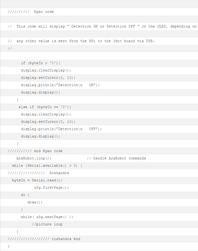
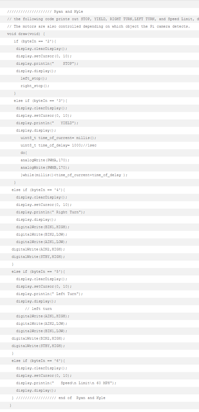
While a serial connection is established between the Raspberry Pi (RPi) and the 3DoT board via the USB; the code at the end of the main loop, the “while (Serial.available () > 0)” code, will determine if there is any information stored in the serial buffer. If the Raspberry Pi detects an image it will send a certain value to the 3DoT board. The 3DoT board will store that value in the variable “byteIn” when the Serial.read() function is called. Next the “Draw” function will be called from the main loop. Based on the value of “byteIn” that gets sent to the 3DoT board by the RPi the draw function will display an image on the 3DoT board’s OLED. In addition, the draw function changes the motors’ settings based on the value of the “byteIn.”
Mechanical/Hardware Design
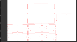
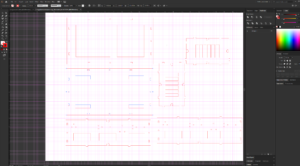
Prototyping for MicroSpot started with laser cut parts that included polypropylene legs and a birchwood laser cut chassis. The designs were created and maintained using Adobe Illustrator.
Chassis was updated to support 4 legs and 4 motors.
When change was made in the project plan to include Mark Plecnik’s 3 leg module, the legs and the chassis went for another redesign in Illustrator. Then the new vector files were sent for laser cutting.
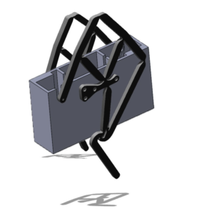
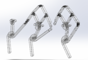
Upon successful prototyping of the 6-legged design with polypropylene and wooden chassis, designs were translated into Solidworks for 3D printing.
The first leg design to confirm a dual material print, featuring Tango, was fit for future usability for the model.
Next, we created a design that used dual extrusion to create flexible joints while using the hard material to provide structure.
The final leg prototype included sleeves for side support to prevent bowing of the legs.
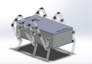
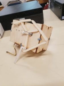
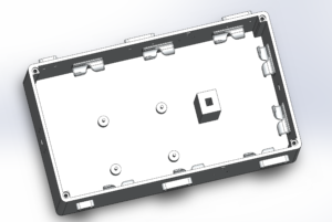
This SolidWorks Chassis was designed to support a pair of legs on each side and one motor one motor on each side of the wall. Since we also had a Raspberry Pi with a camera, holes were made to support an RPi camera-insertion point in the front wall of the chassis. The Chassis also featured a platform for the 3DoT board, to keep it high in the chassis for the sake of seperating it from the RPi.
To top it off, we designed a lid that fit onto the chassis using magnets embedded in its corners for easy-access. The lid has an inlet, or better described as a window, allowing for viewing of the integrated OLED display on a custom shield designed for the 3DoT.
For more in-depth info regarding the design process and various iterations of the prototypes please defer to the design blog-post.
Verification & Validation Test Plan
By Kyle Gee and Ryan Vega:
Our verification plan was to make sure the leg design could provide stability so we started our verification test plan by showing off that MicroSpot is stable even with all of the electrical components. Then we move on to show that our Raspberry Pi recognition software was working and could display the detected signs on the OLED display symbolically. Once that was done, we then connect to the robot via the ArxRobot app through Bluetooth to start controlling MicroSpot. The first action we take is to move it forwards to validate MicroSpot can in fact move forward. Then we start showing the streets signs and the corresponding actions correlated to those signs. For example, when MicroSpot move forwards and is show a stop sign, MicroSpot will stop upon recognition of said sign. Then we show that MicroSpot’s recognition system does turn on and turn off via the app. Lastly, we then take apart and reassemble MicroSpot to show the efficiency of its design.
Concluding Thoughts and Future Work
Kyle Gee:
If I could go back in time and do this differently I would have assigned someone to start learning Solidworks because the legs were a big problem throughout the semester. The joints on the polypropylene were extremely thin and finicky if it did not get cut right. The new 3D printed versions of the legs are a lot more reliable, but the material still seems to tear. I would have really wanted someone to figure out the stress all along the leg to see if it’s just the material that won’t handle the stress or if we needed to move the legs closer together. The coding was not too difficult except for the communication between the Raspberry Pi and the 3DoT. It would have been nice to know that the interrupt pins on the 3DoT top headers are only I2C compatible. You would need to configure other pins if you want interrupts. Another thing is to look ahead in the schedule because the PDR, CDR, and demos come up fast and you want to start working on them early.
Roshandra Scott:
MicroSpot F’19 from day one we all knew it was going to be a difficult project, although we were working off the design on Biped barbEE from previous generation with the leg design coming from University of Irvine: By Mark Plecnik, Veronica Swanson and J. Michael McCarthy. MicroSpot is still a first generation bot, going from four legs with four different motors which after thinking about it was going to be extremely difficult in such a short amount of time. Then we decided to go back to the six linkage leg design (include UCI video from YouTube). With working on MicroSpot you will notice that the leg design is very complex and without the right material it will not even stand. Luckily, we were able to discover Tango material which gave MicroSpot the ability to stand and walk. For the future generations of MicroSpot, I would advise to complete one task and once it is working then improve it; DO NOT IMPROVE AS YOU GO! Also I would start working on the PCB design as early as possible because even with approval for fabrication does not mean it will work after all the components are connected. Good luck with everything looking forward to seeing how MIcroSpot will evolve over time.
Ryan Vega:
I used OpenCV because it was easier to learn than TensorFlow, and it was easier to optimize for the Raspberry Pi. I would recommend anyone who would build off our project to opt for a newer single board computer, and for TensorFlow; although, arguably the next person in my place would be learning TensorFlow from the ground up.
I think a lot of the problems my team endured happened because of a lack of team cohesion, cooperation, and communication. I would advise my future peers to find like minded individuals with similar levels of discipline and effort to themselves, with a desire to earn a similar grade.Future students should strive to find people they can communicate well with; in a way
I am proud of my team and what we have managed to achieve but in many ways were we bottle-necked by our inability to orient ourselves toward the same level of achievement, toward common goals, toward sharing project labors, but most importantly wew were limited by our inability to even think similarly. As we all valued things differently, we all approached target objectives with different levels of energy. Compromise is fundamental to working with others.
Surdeep Singh:
MicroSpot has been a very challenging but very interesting project. It has pushed us to literally take a box and think outside of it. If you review the prototyping and design of this project, it is one of the most revised and updated projects in terms of iterations for a single semester. We started out with laser cut method for both the leg and the chassis. And through trial and error, and constant updates to the design, we were able to create a leg design that took the original concept and improved upon it, making it easier for future generations to evolve and update the project. The biggest challenge with 3D printing was finding the right material. Although we did find a material that works (Tango), it might not have been the best choice. The current filament of tango gets very crusty. The rubber part is not very reliable in the long run as it is not very cohesive for long. It dries up and starts separating from itself, introducing cracks in the joints. We used white gorilla glue that sponges up in the joints that were separating in order to introduce better strength. Future generations should do more research on finding better dual extrusion material or a stronger tango-PolyJet resin prints. There is also a lot that can be done with the chassis. The final chassis we produced was big and heavy due to MicroSpot requiring all the additional components. It can definitely be improved upon by reducing the volume and introducing some cutouts to remove extra bulk and weight. We did something similar while updating our wooden chassis iterations. This can have huge implications on weight of the bot leading to reductions in power consumption overall. MicroSpot truly walks along the engineering method guidelines, pushing one to follow it in order to ensure success. It has great potential to improve and perform interesting feats with future generations.
References/Resources
These are the starting resource files for the next generation of robots. All documentation shall be uploaded, linked to, and archived in to the Arxterra Google Drive. The “Resource” section includes links to the following material.
- Project Video YouTube
- CDR
- PDR
- Verification and Validation Plan
- Solidworks File
- EagleCAD files
- Arduino and/or C++ Code
- Complete Bill of Materials
- Brandon Nguyen’s Github for the original code
- https://learn.adafruit.com/monochrome-oled-breakouts/downloads
- https://www.youtube.com/watch?v=cURh2-dTuI0
- https://www.instructables.com/id/Monochrome-096-i2c-OLED-display-with-arduino-SSD13/
- https://randomnerdtutorials.com/guide-for-oled-display-with-arduino/
- https://www.arxterra.com/getting-started/electronics-and-control-resources/#part15
- https://www.arxterra.com/getting-started/
- https://www.arxterra.com/programming-your-robot-custom-telemetry/
- https://www.youtube.com/watch?v=U36_et5UnxI
- https://www.robot-electronics.co.uk/i2c-tutorial
- https://i2c.info/i2c-bus-specification

