MicroSpot Generation 1 Fall 2019
MicroSpot: Using Shaft Encoder with 3DoT
Author/s: Kyle Gee
Verification: Kyle Gee
Approval: Kyle Gee
Table of Contents
What Are Shaft Encoders
Shaft encoders are device that are attached to the “shaft” of a motor. They are used to monitor the rotation of the shaft. There are several different types of shaft enncoder like one’s that uses optical means, magnet, or conductive. Absolute encoder gives very fine accuracy to what position the shaft is in. It uses gray code on a littld disc to count the position it’s in. Although they are very accurate, they are also expensive. Magnetic shaft encoders will sense either a North Pole or a South Pole of a magnetic field.
Using Quadrature Encoders
For MicroSpot, we are using quadrature encoders from Pololu that attaches to the extended shaft of 120:1 Mini Plastic Gearmotor also from Pololu. On the quadrature encoder PCB are M1, M2, VCC, A, B, and GND pin holes. M1 and M2 are to power the motor, VCC and GRD are power and ground for the components of the PCB. Lastly, A and B are signal outputs for when certain points of the little black disk seen in Figure 1 pass the sensor on the encoder PCB. We needed the quadrature encoders to give us the relative position of the shaft and to give us the speed for each motor. More specifically as the shaft turns we can keep track of the amount of time the encoders are pinged using an interrupt. By comparing the amount of ticks we can adjust motor speeds to get the speeds on each side equal.
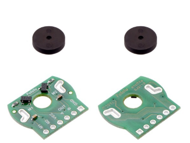
Figure 1. Quadrature Encoder
As mentioned before, pins A and B are signal outputs for the encoders but the main difference between the two is that one of the output is 90o out of phase. In some cases a project would only require only one of the output, but if the project require more accuracy one would want to utilize both outputs. One down side to take into consideration, is by using both outputs results in more interrupts from the pin change interrupt vector which could slow down the overall performance of the project.
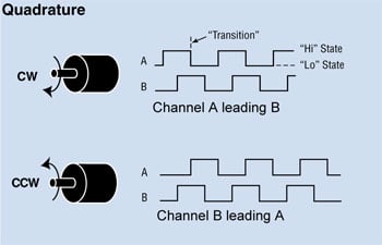
Figure 2. Signal Outputs
Another method one could apply is to lessen the amount of pin change interrupts to the microprocessor. For example if you only wanted the interrupt to occur at the rising edge of the signal, you would want to use the 74HC74 IC chip. The implementation of the chip is shown in Figure 3.

Figure 3. Block Diagram Implementation
How to Set Up ISR
If you did not know the interrupt pins on SDA and SCL are being occupied and cannot be used as an interrupt. That’s why we need to initialize pin change interrupt on either MOSI, MISO, SCK, or SS. By looking at the 3DoT Block Diagram, MISO, MOSI, SCK, and SS are located on PortB and if you remember anything from EE346 Interrupts lecture one need to enable the pins, then enable locally, and lastly globally. (Reference External Interrrupt Lecture) Once the interrupts are enable you can write the code that will be done when the ISR is called. It is important to place the code inside the correct interrupt vector (refer to Figure 4)
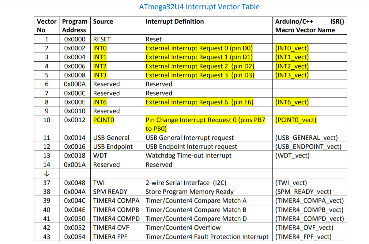
Figure 4. AtMega32U4 Interrupt Vector Table
MicroSpot Code:
ISR(PCINT0_vect){
uint8_t pinStatus= PINB & (_BV(PB2)|_BV(PB0));
uint8_t pinChange= pinLast^pinStatus;
pinLast=pinStatus;
if(pinChange==_BV(PB0))ticksR++;
if(pinChange==_BV(PB2))ticksL++;

}

void setup() {
Wire.begin();
Wire.beginTransmission(0x2F);
Wire.write(53);
Wire.endTransmission();
//pinMode(A4, OUTPUT);
//i2cDP.setSteps(115);

Init3DoT();
//Setting Pin change interrupts
PCMSK0=0x05; //Pins enable// _BV(PB0)|_BV(PB2)// enables SS and MOSI
PCICR=0x01; // Local enable// setting pinchange interrupt enable
sei(); //Global enable
Conclusion
Once I found out that the interrupt pins on SDA and SCL were not available the overall code to make interrupts is pretty straight forward because Professor Hill helped a lot with the code. Using shaft encoders for your project will help you immensly because it provides you a sure way to maintain motor speeds and know a relative position.