Midterm 2 Design Example
In this design example, we are going to design a Slot Machine
Assume Port D is wired as shown in the table below.
|
Direction
|
DDRD bit(s)
|
Type / Initialization
|
PORTD
|
||
|
PD bits 3-0
|
switches
|
Input
|
000
|
Passive Input
|
1
|
|
PD bit 4
|
Win light
|
Output
|
1
|
Initially Off
|
0
|
|
PD bit 5
|
new Account button
|
Input
|
0
|
Active output of a DFF
|
0
|
|
PD bit 6
|
add Account button
|
Input
|
0
|
Active output of a DFF
|
0
|
|
PD bit 7
|
Lose light
|
Output
|
1
|
Initially Off
|
0
|
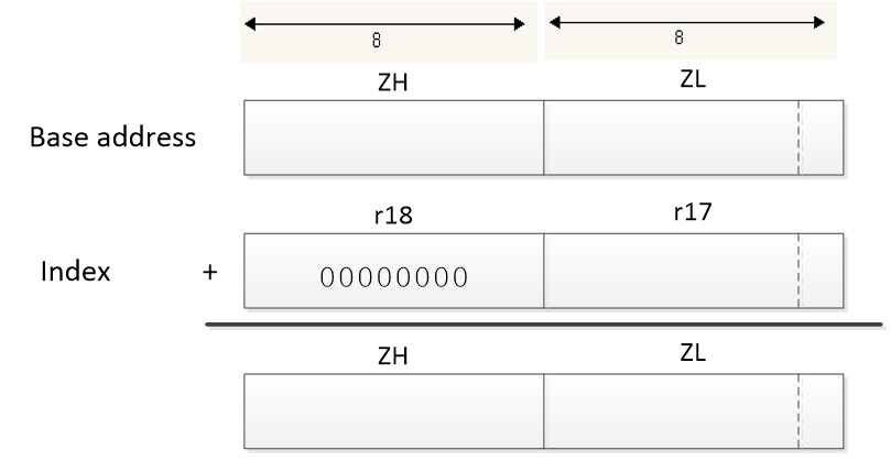
We begin by defining SRAM variable account and initializing Port D as defined in the table.
Now let’s generate a clock to the two D flip-flops so we can read our new and add account button.
Given clock is 20 Mhz. I want to clock the DFF at a Frequency is 20Khz.
Alternative wording: I want to cycle and test if the button is pressed every 50 microseconds.
If I want to use timer 2, what divide frequency will I need to do that? What would you need to load into Timer 2 to generate this delay?

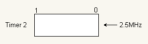
Calculate Max delay given the following information. You are using Timer 2, a clock frequency of fclk = 20 MHz, and a clock divider of ÷8. Timer 2 is an 8-bit timer so the maximum number of tics is 28 = 256 tics. To convert to time we need to equate tics to time.
f1/0 = fclk /8 = 2.5MHz t1/0=1/f1/0 =0.4 µsec/tic
tmax = 0.4µsec/tic × 256 tics = 102.4 µsec
So our timer with given conditions can generate a 25 microseconds delay, now let’s look at what we need to preload our counter with to get a delay of 25 microseconds.
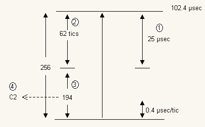
25 µsec ÷ 0.4 µsec/tics = 62.5 tics (Rounding down we leave it at 62). So we would need to preload timer 2 with a value of 256 – 62 = 19410 = 0xC2
We can now use polling or an interrupt service routine to generate our clock.
Now let’s generate the subroutines to be called when the user sets a dollar amount into 4-switches and presses the new account or add account button.
The Slot Machine Wheel
The strange characters to be generated by our slot machine are shown at left. In the table are the segments to be turned on/off to create the strange symbols.
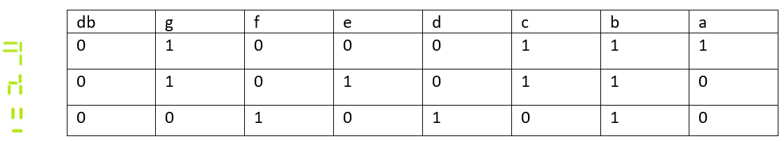
Converting this table into bytes to be saved in Flash.
0x0123 wheel: .DB 0x47, 0x56, …..0x2A