Mini-Rosco Generation 1 Summary Blog Post
Author/s: Alexander Margaris (Project Manager) , Darren Chan (Design and Manufacturing) , Giann Bullo (Electronics and Control)
Table of Contents
Executive Summary
Written by: Alex Margaris (PM/MST)
Quite often, people require the need to view an environment or perform reconnaissance on a particular person or object. Mini-Rosco will accomplish all simple reconnaissance needs by locating its target and following its target while continuously relaying information about how far away the target is. Once its target is found, a video feed of the target will be captured via a smartphone camera.
Program and Project Objectives
Written by: Alex Margaris (PM/MST)
Program Objectives
The national robot trade show is approaching in May 2020 and many robot companies will be showcasing their new products. The TRC company will have its own demonstration area where it will show the many capabilities of the 3DoT board through the use of innovative robots. Our current filming robot Rosco, has the ability to mount a smartphone on it to record footage of the other robots. However, its large form factor will distract viewers from the other robots we are showcasing. Additionally, it does not have the capabilities required to autonomously locate and follow other robots. Your team’s objective is to design and 3D print / laser-cut a miniaturized prototype of Rosco to unveil at the convention. The Mini-Rosco will feature autonomous following so that it may capture footage of other robots of similar size via a mounted smartphone’s camera linked to the ArxRobot application and Arxterra application, enabling the TRC company to use any captured footage as marketing material. Mini-Rosco must have the ability to locate and go to another robot so that the trade show specialist can easily and autonomously control Rosco. This project is limited to using a single 3DoT shield to implement any pertinent features. Similarly, this project is also limited to software use of the Arxterra application and ArxRobot mobile application. In order to achieve maximum cost efficiency as well as power efficiency, Mini-Rosco must maintain as small of a size as possible. Please be cognizant of the fact that this project will be used to film other robots, therefore stability and maneuverability are key underlying features.
Project Objectives
The Mini-Rosco is the first generation Mini-Rosco and will enable trade show specialists to capture footage of Arxterra, Humans for Robots, and EE 400D robots. To meet our Program Objectives the first generation of Mini-Rosco will introduce new design features such as autonomous locating features, autonomous following features, and a miniaturized form factor than that of Rosco. The objective of the Mini-Rosco project is to create a robot that can assist the TRC company in trade shows in order to capture footage showcasing the capabilities of the 3DoT board. There will be Arxterra and ArxRobot controls integrated into the overall design.
Mission Profile
Written by: Alex Margaris (PM/MST)
The prototype Mini-Rosco is designed for robot enthusiasts to use for footage of other robots. Footage captured via a smartphone’s camera mounted on Mini-Rosco can be viewed in a real-time stream and by everyone logged into our telepresent application.
Another robot’s location will be acquired by Mini-Rosco via the Arxterra and ArxRobot applications. Mini-Rosco’s position will be acquired, in addition to another robot’s position. Mini-Rosco will then make any necessary calculations in order to move to the other robot’s location within a maze. The other robot’s location will be transmitted to the user through the use of a custom GPS PCB.
Once Mini-Rosco reaches the other robot’s location, Mini-Rosco will demonstrate fully autonomous following of another robot through a maze in order to capture video footage at different angles. Mini-Rosco’s handheld size allows it to maintain speeds faster than or equal to that of other robots, while maintaining stability required to securely hold a smartphone and maneuverability required to follow the TRC robots at the convention (built in class).
Project Features
Written by: Alex Margaris (PM/MST)
Solidworks Design by: Darren Chan (Design and Manufacturing)
The detailed design features of Mini-Rosco are stated below. For the sake of clarity, these features have been segmented into two different subsections: Physical and Software.
Physical:
- Mini-Rosco utilizes two plastic gear motors. One is placed such that it connects to the right track and the other is placed such that it connects to the left track.
- Mini-Rosco features a chassis that is approximately 75% smaller than the chassis of Rosco.
- Mini-Rosco features four wheels and two treads. There are two wheels per tread.
- Mini-Rosco features a front wheel drive, drive train.
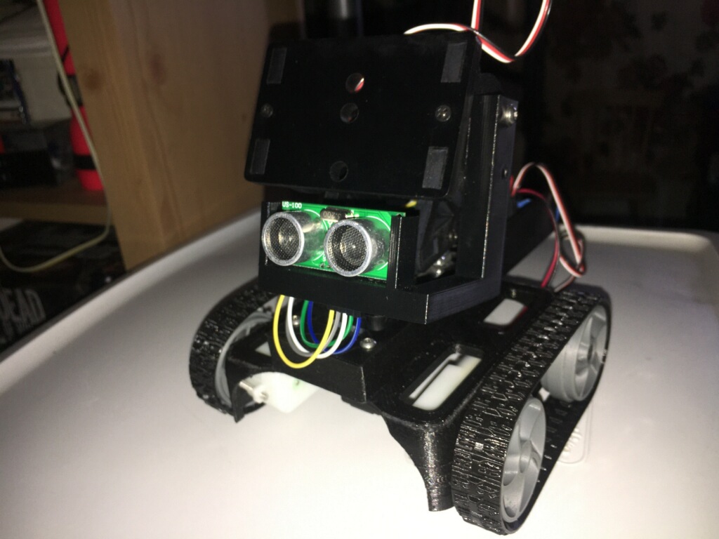
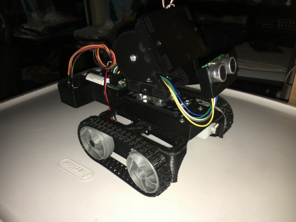
- Mini-Rosco features a pan and tilt platform with a secure cellphone mount.
- Mini-Rosco features a ultrasonic sensor mount on the pan and tilt platform.
- A PCB is placed behind the pan and tilt platform, on the rear of the chassis.
Software:
- GPS navigation using a singular way point.
- Mini-Rosco will feature an obstacle detection and avoidance algorithm.
- Autonomous driving mode.
- The ability to follow other objects, mainly Arxterra robots.
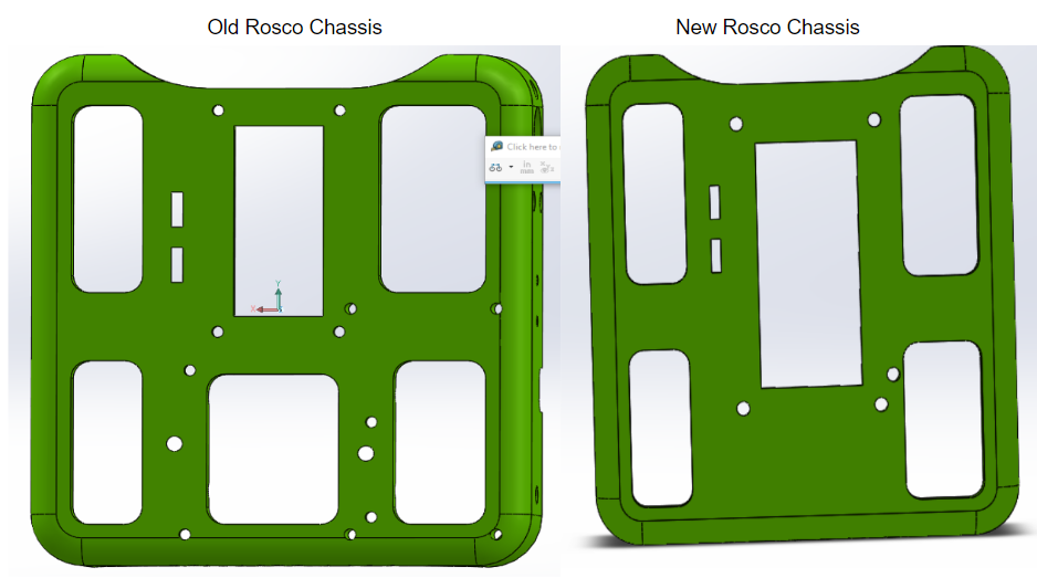
The figure below demonstrates the re-design of Rosco’s chassis. While these images only serve as a surface view of the features added to Mini-Rosco, the complete list of them are discussed in the Mechanical and Hardware design portion of this report.
Requirements
Written by: Alex Margaris (PM/MST)
It should be noted that due to limitations placed on this project by “stay at home” conditions enforced by California State University Long Beach, this project will not include the implementation of L2 Performance Requirements. Therefore upon inspection of this project it is impossible to say whether a certain parameter was under designed or over designed.
Engineering Standards and Constraints
Written by: Alex Margaris (PM/MST)
Applicable Engineering Standards
- IEEE 29148-2018 – ISO/IEC/IEEE Approved Draft International Standard – Systems and Software Engineering — Life Cycle Processes –Requirements Engineering.
- NASA/SP-2007-6105 Rev1 – Systems Engineering Handbook
- Bluetooth Special Interest Group (SIG) Standard (supersedes IEEE 802.15.1)
- C++ standard (ISO/IEC 14882:1998)
- Federal Communications Commission (FCC) Relevant standards for a product implementing a 2.4GHz radio, FCC Intentional Radiators (Radio) Part 15C, and Unintentional Radiators FCC Part 15B for CPU, memories etc.
- NXP Semiconductor, UM10204, I2C-bus specification and user manual.
- ATmega16U4/ATmega32U4, 8-bit Microcontroller with 16/32K bytes of ISP Flash and USB Controller datasheet section datasheet, Section 18, USART.
- USB 2.0 Specification released on April 27, 2000, usb_20_20180904.zip
- Motorola’s SPI Block Guide V03.06
Environmental, Health, and Safety (EH&S) Standards
- All Lithium (Li-ion, Li-polymer) batteries shall be purchased with and stored, when not in use, in a fire and explosion proof battery bag.
- CSULB COE Lab Safety
- CSULB Environmental Health & Safety
- IEEE National Electrical Safety Code
Project Level 1 Functional Requirements
Written by: Alex Margaris (PM/MST)
The Level 1 Functional Requirements seen in Mini-Rosco generation one stemmed from the need to complete a specific mission of locating and following other robots at a trade show. Thus the requirements listed below pertain the the electrical, mechanical, and software design of Mini-Rosco. It can clearly be seen below that all L1 Functional Requirements meet the criteria of being: quantifiable, verifiable, and realizable.
Movement Requirements
L.1.1-Mini-Rosco shall operate for a maximum of 30 minutes. It should be noted that this 30 minute timeframe begins only after the GPS PCB has acquired a signal. This may take an average of 10 minutes.
L.1.2- Mini-Rosco shall be able to articulate the camera feed using a pan angle of 360 degrees and a tilt angle of 135 degrees using the mounted iOS/Android smartphone. These are the optimal camera degree field of views due to the fact that Mini-Rosco will be filming other moving robots. The tallest robot is 2 feet, the booth is 10 feet wide and the mini-rosco will be located inside the booth.
L.1.3-Mini-Rosco shall have the ability to make turns to the left and to the right within the range of 0-360 degrees with an accuracy of +/-10 degrees. This is necessary for navigating tight turns within the booth as other robots may
L.1.4-Mini-Rosco shall have the option of being controlled in Remote Control mode. All movement requirements shall be demonstrated remotely. This will be done through the ArxRobot application.
L.1.5- Mini-Rosco shall be controlled for the duration of the mission through the Arxterra control panel. Mini-Rosco is operated from our video booth.
GPS Navigation Requirements
L.1.6- Mini-Rosco will be able to accept user input through a waypoint for a specific destination to travel to.
L.1.7- Mini Rosco shall be able to navigate to specific locations based on GPS coordinates within an accuracy of a minimum of 4 ft.
Acquisition Requirements
L.1.8- Mini-Rosco shall recognize another robot within a 4 feet radius using an ultrasonic sensor after arriving at the specified destination. The other robot that is being followed is 1 foot in height.
Following Requirements
L.1.9- Mini-Rosco shall maintain a following distance of 1 to 2 feet after locating another robot. The other robot’s speed is within the range of 1 to 3 miles per hour.
Software Requirements
L.1.10 – Mini-Rosco shall have an autonomous navigation mode in order to travel to desired destination.
L.1.11-Mini-Rosco shall avoid obstacles up to 70cm away while in autonomous mode.
L.1.12-Mini-Rosco shall execute its mission in three stages. The first stage will be the the Locating stage seen in requirement L.1.7. The second stage will be the Acquisition stage see in requirement L.1.8. The third stage will be the Following stage seen in requirement L.1.9.
Custom Shield Requirements
L.1.13 – Mini-Rosco shall employ a custom PCB to extend the functions of the 3DoT by allowing control over where Mini-Rosco travels via a set of coordinates
3D Modeling Requirements
L.1.14 – Mini-Rosco will be a smaller scale model of 70% to 80% the size of Rosco for storage purposes.
L.1.15- Mini-Rosco will be designed such that the 3DoT board fits onto the chassis.
Cost Requirements
L.1.16- Mini-Rosco’s expenditures shall not exceed $500.
Hardware Requirements
L.1.17 – Mini-Rosco will be designed such that the same number of motors and servos are equal to that of the original Rosco.
L.1.18– Mini-Rosco will utilize the 3DoT board to control the robot.
Control Panel/App Requirements
L.1.19- Mini-Rosco shall provide a live stream video feed via the Arxterra control panel throughout the duration of its mission.
Constraints
- Mini-Rosco shall be constrained to a cost not to exceed $500
- Mini-Rosco shall be constrained to a completion date of May 15, 2020.
- Mini-Rosco shall contain a custom 3DoT shield incorporating interface electronics between the 3DoT board and sensors and/or actuators unique to the robot.
- Mini-Rosco shall be disassembled and reassembled in 20 minutes or less.
- Mini-Rosco shall be designed such that there are no dangling wires.
- Mini-Rosco shall incorporate the 3DoT v9.05 or later series of boards.
- Software shall be written in the Arduino De facto Standard scripting language and/or using the GCC C++ programming language, which is implements the ISO C++ standard (ISO/IEC 14882:1998) published in 1998, and the 2011 and 2014 revisions.
- Mini-Rosco shall be controlled via Bluetooth 4.0 in compliance with the Bluetooth Special Interest Group (SIG) Standard (supersedes IEEE 802.15.1).
- Manufacturability of 3D printed robots shall utilize as few files as possible when 3D Printing the Robot and its parts.
System/Subsystem/Specifications Level 2 Requirements
Written by: Alex Margaris (PM/MST)
As previously stated, due to “stay at home” constraints placed on our group due to COVID-19, L2 Performance Requirements were not attempted. However, for the sake of completeness, some will be included in this Final Blog Post.
Movement Requirements
L.2.3.1 – Mini-Rosco will execute turns at a speed of 1.5 miles per hour.
L.2.3.2 – Mini-Rosco will be able to travel up a 15 degree incline at a speed of at least 1 mile per hour.
L.2.3.3 – Mini-Rosco will travel down an incline of 15 degrees at a speed of no greater than 1 mile per hour.
L.2.9.1 – Mini-Rosco will actively speed up or slow down by 2 miles per hour in order to say within 1 to 2 feet of the other robot it is following.
L.2.11.1 – Mini-Rosco will change direction in less than 2 seconds after detecting an obstacle.
L.2.13.1 – Mini-Rosco will employ a custom PCB that does not cost more than $20 to produce.
Allocated Requirements / System Resource Reports
Written by: Darren Chan (Design and Manufacturing)
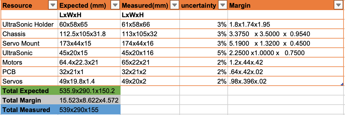
The estimated weight for various pieces that we made for our project was calculated mainly through solid works. Solid works allows one to select the type of material a piece will be made out of and from there check the amount of mass that it will take up. This is done by first selecting the material value of the individual piece. Generally pieces are not assigned a material, so in order to do you need to navigate to the left side of the screen where it shows material. From there we can select our material from a variety of options that solid works has available. Once the material is set, we go into tools where we find the option for mass. In this page we can see certain parameters such as density, but in this case we are focused on mass. This value was then recorded for our table. As solid works also has options to select plastic materials, we expected that the weight would not change much once the parts had been printed. Other pieces that were not created in solid works such as the electrical components which were the ultrasonic, motors, and servos, the estimated weight was taken from the website from which they were acquired. As most websites had this information easily accessible, the electrical components had the easiest mass value to estimate. All values had low uncertainty percentages due to the fact that there were solid sources from where the estimated measurements were taken from. In order to measure the weight the student used a scale for individual pieces.
Written by: Giann Bullo (Electronics and Control)
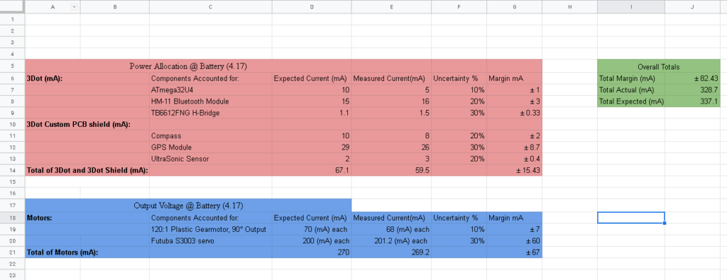
The power allocation came from testing each component of the project individually at the same voltage to estimate the max power drawn from every motor, servo, and electric part of the robot. It should be noted that due to “stay at home” constraints placed on us by the school I was unable to obtain accurate readings. This means that the current measured was used by tools that would not specifically determine the correct currents. We can see how much current each electronic device of the 3Dot would use and compare them to the expected value from the manufactures website. Our actual measured current was either smaller or close to the expected current, with the majority of the resources using below the expected. The only problem was the servos being used. When working with the robot, we noticed that the servos took the most current when trying to move the pan and tilt system of the Mini-Rosco. This is due to the fact that the servos are standard where the 3Dot can only supply micro servos. The robot was not able to control both pan and tilt systems at the same time when both servos were connected. This has led the group to employ the current limiter of the 3Dot.
Our first solution to allow the use of both servos was to limit the current of each device being connected to the 3Dot. This will ensure that the minimum amount current needed for the servos are met. To increase the amount of current we can provide to our servos we lowered the limiter value, but setting this value too low causes the other devices to fail. As a result we would approach the problem in a different way where instead on controlling both for autonomous mode we would only employ the pan system to search for objects in front of the robot. This insures that at least one servo is meeting the current requirements and are fully functional.
Written by: Darren Chan (Design and Manufacturing)
Size
The size for the multiple pieces of the project was calculated in a similar way to the weight. For pieces that were created in solid works, the student was able to use solid work tools in order to get a measurement on individual pieces. This was done using the measure tool and by selecting either the opposing points for non straight figures or the boundaries if the figure had straight flat surfaces. Solid works also provides a tool to allow for one to acquire the surface area, however since this was not what the group needed this tool was not used. For the electronic components just like with the weights, the manufacturer’s data was recorded as an estimate. As the printed parts may have slightly altered during the printing process, the uncertainty was higher than those produced by a large manufacturer. In order to measure the pieces, a ruler was used measuring in millimetres.
Project Report
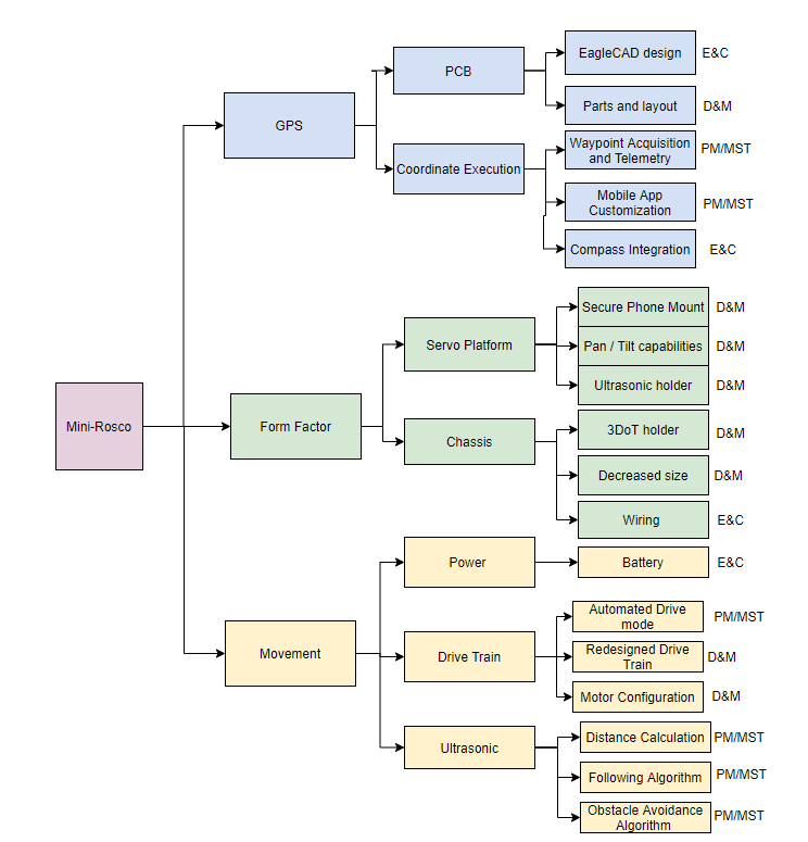
In order to effectively define and organize tasks that needed to be done and who needed to do them, two different reports were created. The first report that was created was the Work Breakdown Structure, which organizes the project by allocating certain work to team members. The second report that was created was the Product Breakdown Structure, which organizes the project by product features that need to be implemented.
Project WBS and PBS
Written by: Alex Margaris (PM/MST)
Work Breakdown Structure (WBS)
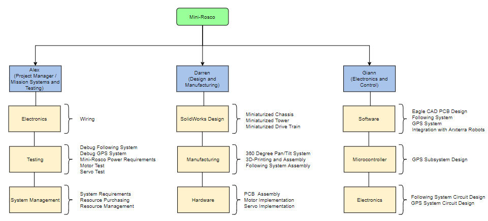
Mini-Rosco’s Work Breakdown Structure divides the work across each of the three group members. Each of the three categories under each group member are based on their title and role. Some categories, such as electronics and hardware can be seen across multiple team members. It should be noted that some tasks between team members may overlap. If this is the case, then those team members will collaborate on those specific tasks.
Product Breakdown Structure (PBS)
Mini-Rosco Generation 1 was segmented into three primary parts of the product: GPS, Form Factor, and Movement. The GPS further breaks down into multiple categories pertaining to the PCB and the coordinate execution that needs to be accomplished so that Mini-Rosco can complete its mission. The Form Factor breaks down into the Servo Platform and the Chassis. Because the drive train was not shrunk or completely overhauled and only slight modifications were made, it was not included in the Form Factor section. The final segment, Movement, was broken up into three subsections: Power, Drive Train, and Ultrasonic.
It should be noted that for reference:
E&C = Giann (Electronics and Control)
D&M = Darren (Design and Manufacturing)
PM/MST = Alex (Project Manager / Mission Systems Test)
Cost
Written by: Alex Margaris (PM/MST)
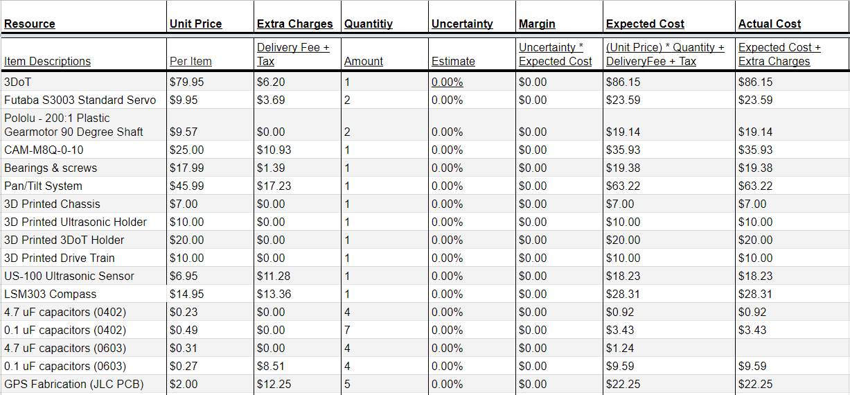
It can be seen below that Mini-Rosco did not exceed the total expected cost that was planned in the early stages of this project. Mini-Rosco also managed to go under budget by a total of $122.86. A reason that we were able to go so far under budget is due to the fact that 3D printing was limited due to constraints placed on our group by the school to “stay at home.” One unforeseen cost was the purchase of a digital compass which Mini-Rosco needs to orient itself.
Below is a list of all components and parts purchased to construct Mini-Rosco.
Schedule
Written by: Alex Margaris (PM/MST)
The first schedule show below was created on Draw.io and is representative of how the project should progress on a week by week basis. The strength of this view is it clearly allows the reader of the schedule to follow the task flow and understand which parts of the project correlate or overlap.
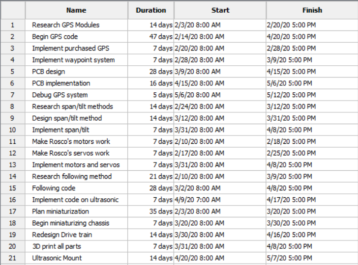
The second two schedules shown below were created on ProjectLibre. If they were lined up next to each other, each row in the duration breakdown corresponds to a row in the waterfall schedule. The strength of this is that it clearly gives the user insight as to how long each task should take. It should be noted that this schedule was created prior to the project’s start and is not indicative of progress made. For more information on progress made and percent completion please see the burn down section of this blog post. It should be noted that the full report is linked at the end of this blog post in the references section should more information be desired
Burndown and/or Percent Complete
Written by: Alex Margaris (PM/MST)
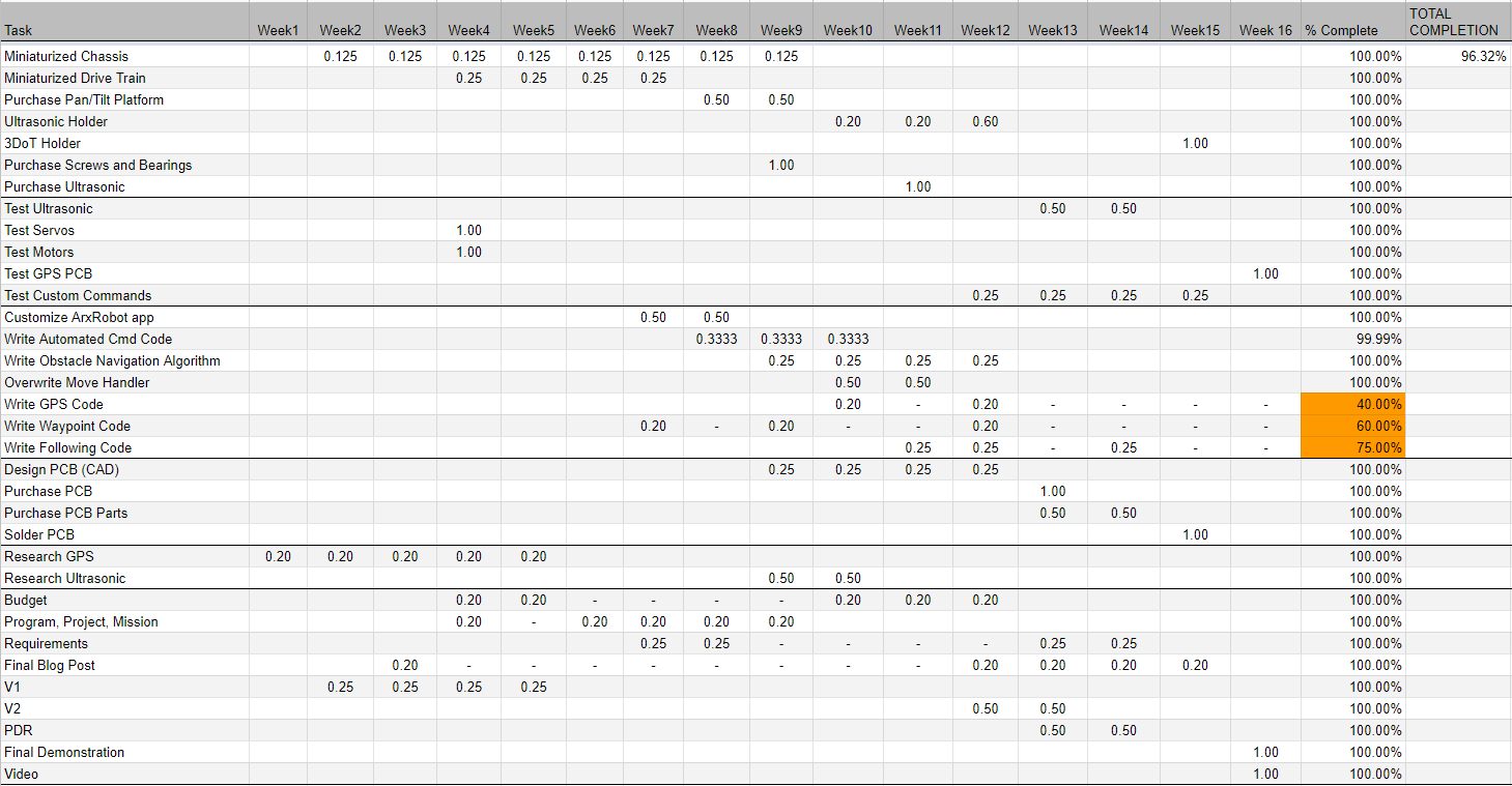
The Burn Down Schedule below is representative of the completion of Mini-Rosco generation 1. It can be seen in the top right hand corner that Mini-Rosco was approximately 96% complete. Aspects that we were not able to complete revolved around the GPS functionality of Mini-Rosco.
Concept and Preliminary Design
Written by: Alex Margaris (PM/MST)
In order to complete Mini-Rosco, research on how to execute certain methods needed to be completed. In addition to research, Mini-Rosco also employed the method of concept of operations (ConOps) such that fatal design error during the project’s operation of its mission was avoided.
Literature Review
Written by: Alex Margaris (PM/MST)
The two primary aspects of research that this project focused on was researching how GPS can integrate with Mini-Rosco and how to program the robot to to accomplish the mission.
Part of the challenge with understanding how the GPS could be integrated into our mission was determining to what extent we had the capacity and time to implement something. This meant brainstorming and conducting ConOps to determine if our original design contained any fatal design flaws that would hamper our progress during the project life cycle. Much of our research was conducted via analyzing various data sheets from companies such as SparkFun and Adafruit to determine what designs we could accomplish, as well as what designs were the best suited for our scenario and needs. For example, one of the primary features we considered when designing our own PCB included an internally integrated antenna to conserve space on the miniaturized chassis of Rosco. A complete set of references can be found in this blog post.
In order to understand how to program the robot such that we are able to execute our mission, Arxterra resources were extremely helpful for us. Namely the extensive tutorials on the 3DoT and how to use it. Another Arxterra resource we used however was studying the .cpp and .h files within the ArxRobot Library to familiarize ourselves with the syntax and functions used. Another incredibly useful resource was Professor Gary Hill, Christopher Hirunthanakorn, Jeff Gomes, and Jaap de Dood. These four individuals were instrumental in aiding our comprehension and execution of the programming of Mini-Rosco, as well as aid in understanding and executing the SolidWorks aspect of the project.
With the information gathered from the documents below, we were able to better understand how to implement a more well designed version of Mini-Rosco than we had originally planned.
Design Innovation
Written by: Darren Chan (Design and Manufacturing)
- UltraSonic Holder – Implementation of a device to allow for simultaneous movement of the pan and tilt platform and the ultrasonic. By creating a custom made ultrasonic holder, the group was able to implement an ultrasonic that moved in sync with the camera located on the front of the robot via phone. In addition, by utilizing the screws on the side of the phone holder, a cleaner design was able to be implemented for seamless integration.
- Servo mount – Due to printing restrictions, the robot used a mount for the servo in order to allow the robot to function as intended. As the pan and tilt servo was extended farther down than the height of the robot the robot was effectively stopped from moving. The servo mount worked to alleviate this problem by extending the height of the robot, while also giving the pan and tilt platform a stable spot to rest on the robot as the initial opening was made for a different servo combination. In addition, the servo mount also worked to allow the 3dot to fit on the chassis as a cutout was made in order to allow it to move with the robot.
Conceptual Design / Proposed Solution
Written by: Giann Bullo (Electronics and Control) and Darren Chan (Manufacturing and Design)
One of the biggest problems that the team faced when creating the project was implementation of the waypoint algorithm for the robot. At the beginning of the semester we believed that the GPS module would be sufficient enough in getting from point A to B. This, however, proved to unlikely due to the fact that without the a compass that can get the x, y, and z headings of the robot then it would be impossible for it to move to the specified location. This would pose design obstacles such as
- Complicated logarithm for waypoint without a compass
- Inaccurate movement of the robot
Instead of trying to figure out how to create these complicated algorithms on Arduino, the team decided to add on a magnetometer and configure it into a compass. This method would ultimately reduce the time to figure out the code and simplify it.
Another problem was the GPS module component that the team chose. When working on the PCB shield Giann found out that the PAM 7Q GPS module that was going to be used was already a PCB in itself. If chosen the team would only have to create pin connectors on the shield for it to be connected. This would defeat the whole purpose of building a shield for the 3Dot. Giann, instead, did research on new GPS modules that were SMD/SMT and similar to the PAM 7Q so that the work already done would not be a waste of time. He found a new module that was a surface mount and would satisfy the shield requirements.
A manufacturing problem that the group encountered involved the use of the new pan and tilt platform that the group purchased in order to replace the older model that was available with rosco. The old pan and tilt configuration of old rosco had the servo sit in a servo block evenly with the chassis with the servo block acting as a pressure relief for the servo. When the chassis was shrunk down as intended from our goals, the space that the servo block occupied was kept the same in order to utilize the space once a replacement servo platform was bought. The height of the mini-rosco was also re-extended as the walls of the chassis had been shrunk down when the entire robot was scaled. This had to be done in order to allow for the motors to fit within the new chassis. As the group was time constrained the print for the chassis of the 3dot was sent to the innovation space before a new pan and tilt platform could be acquired. This would later on lead to a problem as the new pan and tilt platform utilized a different method of relieving the pressure on the servo that caused the servo to sink much farther down then the older servo configuration. In addition the new platform was smaller than the servo block as it did not use the same method in keeping the servo suspended.
As reprinting the chassis was not an option the group decided to instead implement a new feature onto the chassis that would make up for both the overextending servo and the too wide opening. This method was the servo mount that would later on include a space for the 3dot and the compass. The mount was created to line up with the pre existing screw holes originally used for the servo block in order to limit the number of new additions and glue that would be used. After creation, the mount not only raised the servo to the correct height, but it also allowed a more stable platform for the servos, as the opening of the mount was designed to fit the base of the platform exactly. Because of this the platform no longer swayed when placed on the robot. The mount is attached using only 2 screws which screw into the front of the mount through the chassis.
System Design / Final Design and Results
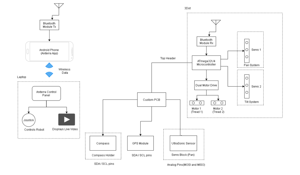
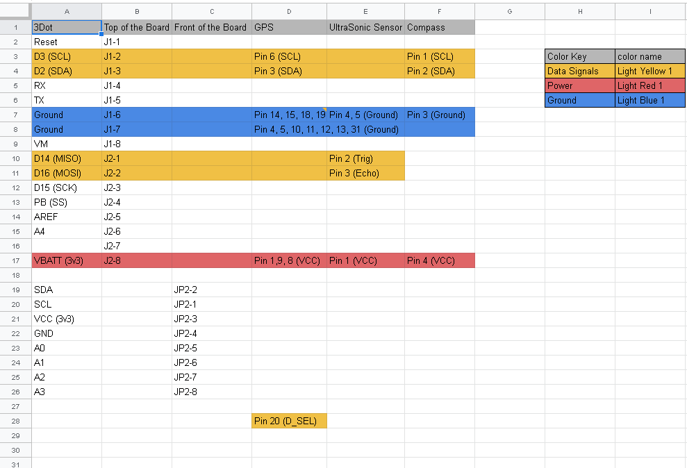
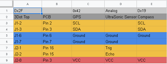
The following section represents the system block diagram, interface matrix, and cable tree of the project. In this portion of the project we have added a magnetometer to the project in order to get better results for the implementation of the waypoint aspect of the project. This has been the only notable change to the project in its final design process.
System Block Diagram
Written by: Giann Bullo (Electronics and Control)
The system block diagram that we created shows the various systems and subsystems of the Mini-Rosco. It details how each part of the robot is controlled and where it will be located. The left side shows how the robot will be controlled via the control panel on a laptop. A smartphone will be connected to the 3Dot’s UART serial communication which will then broadcast a live video of the robots point of view. It will then connect to the control panel in order for the user to have full control of the robots features and movement. The right side depicts the 3Dots different systems that it will be controlling. Its two servos will connect to the pan and tilt system of the robot while its dual motor drive will control the treads of the robot. In order to be able to connect to the GPS module, magnetometer, and compass, the 3Dot will connect to a custom PCB via its top connection header. This custom PCB will then have these different electronic parts connect via the different serial communications. The compass will be located right next to the 3Dot on a 3D printed holder while the ultrasonic sensor will have its own holder attached to the servo that controls the pan aspect of the robot.
Interface Definition
Written by: Giann Bullo (Electronics and Control)
For the interface matrix we are using only one header section on the top of the 3Dot. The front headers will not be used for this project. The matrix describes how we plan on utilizing and implementing each part of the robot to the 3Dot.
Modeling/Experimental Results
Written by: Giann Bullo (Electronics and Control) and Darren Chan (Manufacturing and Design)
GPS acquirement Experiment
In order to get the GPS coordinates via I2C code was written to understand how to acquire the information. At first the group attempted to learn how to code using the wire library. Upon further research into the subject they were able to find a spark fun library online that would simplify the code as it uses pre-made functions created by spark fun. So instead they used the code to experiment on how to implement these readings into the telemetry firmware. More on my GPS experiment can be found here.
UltraSonic Sensor Distance Experiment
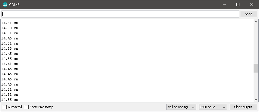
To utilize the ultrasonic sensor the team had to figure out how to acquire the distance of the object. This would be imperative in order to implement the following objective of the project. The basic principle of ultrasonic distance measurement is based on ECHO. When sound waves are transmitted in environment then waves are return back to origin as ECHO after striking on the obstacle. So we only need to calculate the travelling time of both sounds. So from outgoing time and returning time to origin after striking an obstacle. As speed of the sound is known to us, after some calculation we can calculate the distance. An in depth look at how the ultrasonic sensor will be implemented can be found here.
Modeling
Due to the limited printing capabilities for our project, before any file was sent for 3d printing, testing and modeling of the pieces had to be done in order to conserve our finite resources.In order to ensure the smallest margin of error for our prints, it was suggested that we use models of generic devices in order to test the designs in solid work. These general objects such as servos or ultrasonic can be found in forums where people post popular device shapes in order to test functionality using solid works . In order to do this the group found files close to our ultra sonic and servos and tested them against the new equipment that was to be printed.
The picture above shows how the test looks solid works. The pieces that corresponded with each other would be added to the same assembly file and from there the pieces would be mated together. This tool in assembly helps to line up objects and surfaces and makes it easier to test dimension parameters. In addition, one can still move the pieces while they are mated, which means it is possible to also test moving pieces to see if they conflict with designs. The first modeling that was done involved the use of the ultrasonic and the holder. By modeling the design with the model taken from online, we were able to avoid errors in our printing. The most noticeable was that the back panel of the holder used to be a wall instead of a cut while a hole was placed at the bottom. This was due to the fact that the image of the ultrasonic made it appear as if the pins would extend from the bottom and from the back. By using the model, the group was able to correct this mistake. In addition, the group was also able to better line up the indentation which would hold the ultrasonic since there was a visual reference which could be used to set a guideline. Originally the case was made with estimates as the ultrasonic had not arrived yet, however by using the model, a lot of errors in creating and printing the piece were avoided. A deeper look can be found in this blog post.
The picture above shows another piece which benefited from modeling which was the mount. Created in order to compensate for a low hanging servo the mount was made with the intention to use minimal tools in order to attach. Because of this, previous screw holes were recreated on the mount which would allow for a long screw to attach through the chassis. In addition, a snug fit would be designed for the servo in order to allow for stability. In order to meet these goals, the mount was modeled with the chassis and the screw holes were mated together in order to check for sameness. A servo piece was found from an online forum that resembled our current servo and thus used to check if the cut made for the servo would fit snug enough to stop movement. When all goals were met and checked off the pieces were finally printed. A deeper look can be found in this blog post.
Mission Command and Control
Written by: Alex Margaris (PM/MST)
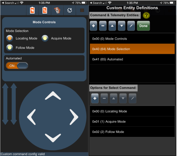
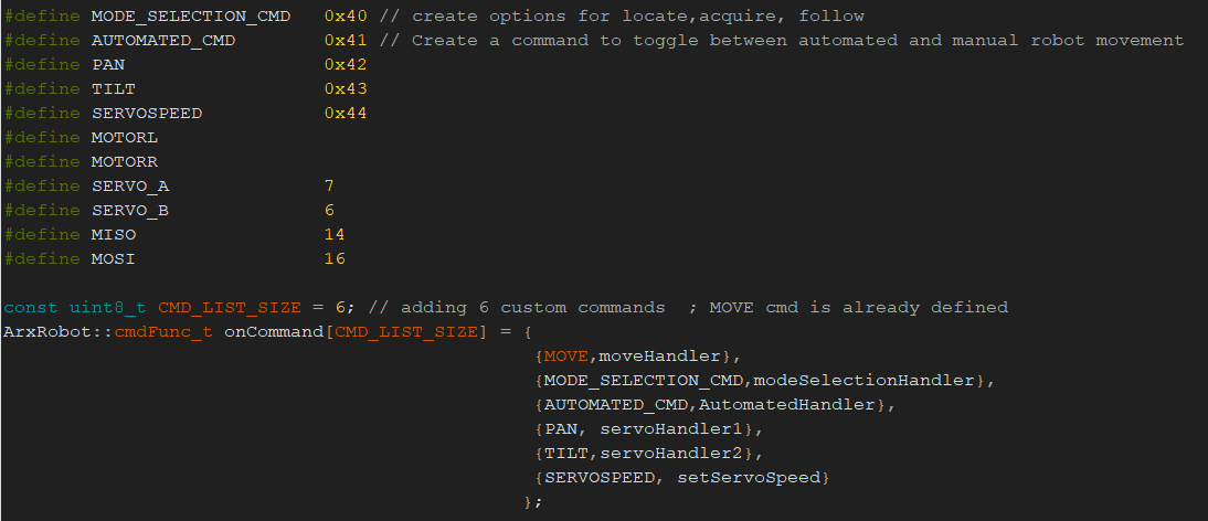
Below is a screenshot of the custom commands the Mini-Rosco generation 1 used in order to complete the mission. It should be noted that Mini-Rosco was primarily controlled through the Arxterra Control Panel. This section will include a brief overview as to what each command is, its address, and its purpose.
- Mode Selection – 0x40 (64) – This custom select variable controls which mode Mini-Rosco is in during each stage of the mission. Only one stage of the mission can be active at a time.
- Locating Mode – 0x00 (0) – This mode will only function if Automated mode is “ON.” It allows Mini-Rosco to automatically navigate to a way point, avoiding obstacles along the way.
- Acquire Mode – 0x01 (1) – This mode will only function if Automated mode is “OFF.” It will allow Mini-Rosco to be controlled in remote control (RC) Mode. Note that RC mode is a default mode in the Arxterra platform.
- Follow Mode – 0x02 (2) – This mode will only function if Automated Mode is “ON.” It will allow Mini-Rosco to follow an object in motion.
- Automated – 0x41 (65) – This custom boolean variable controls whether or not Mini-R0sco will drive in Automated Mode or Manual mode. If Automated is “ON,” Mini-Rosco’s motors will not need any direct input for the Locating and Following stages of the mission. If Automated is “OFF,” Mini-Rosco’s motors will require direct input as Mini-Rosco will be in RC mode.
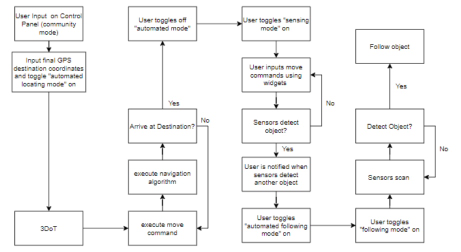
The block diagram below represents the software systems that Mini-Rosco uses. The first column of the block diagram is indicative of the user inputting a way point coordinate via the Arxterra control panel. The second column of the block diagram represents the logic that takes place as Mini-Rosco travels towards its destination. It should be noted that both the first and second column take place in the Locating stage of the mission. The third column represents the logic as Mini-Rosco is positioned in front of an object it will follow. The third column correlates to the Acquisition stage in the mission. The fourth column represents the following stage of the mission.
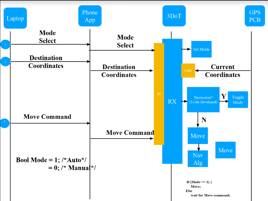
The final figure in this section is the sequence diagram representing the flow of commands between the Arxterra Control Panel, the Phone application, the 3DoT, and the GPS PCB during the locating stage of the mission.
Electronic Design
Our Electronic design consists of one custom PCB that would connect through the top header of the 3Dot. The PCB would be used to control the GPS module, magnetometer, and ultrasonic sensor.
PCB Design
Written by: Giann Bullo (Electronics and Control)
For our PCB, the aim was to create a board that was capable of being mounted onto the top of the 3Dot to control each electronic part being used in the project. This meant that we would need to create a board that would fit every component. Building each component on the board would not be possible since there is not enough space on the top of the board so the team decided to create pin connectors and connect them via jumper wires. This would save the team time and resources that can be used elsewhere. The design process of the PCB can be found here where it describes each iteration of the schematic and board.
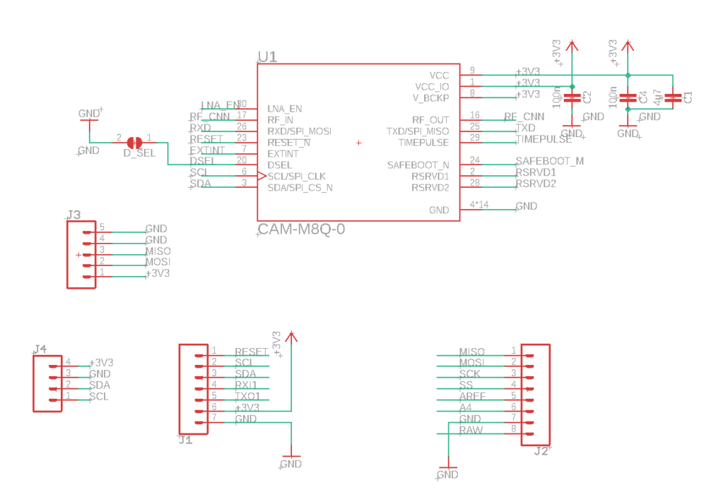
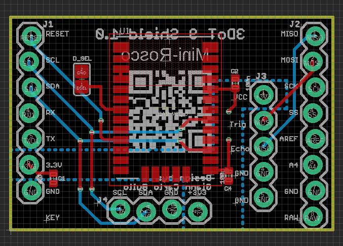
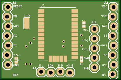
The schematic for the final iteration of the PCB board can be found below that utilizes I2C and SPI communication. The GPS module and the magnetometer will get its info via the I2C communications. Since the 3Dot will be utilizing the RX and TX communication for Bluetooth the only way for the GPS to get its info is through the I2C pins. The ultrasonic sensor would need to re purpose the SPI serial communication as UART communication since they will not be used in the project at all.
Below is the V3 (final design of the 3Dot sheild. It was changed quite a lot compared to the previous iteration in order to create a cleaner and more efficient board layout. The board dimensions are 32mm by 21mm which means it perfectly connects to the top of the header without taking any more space needed. Since our goal was to miniaturize the Rosco we were mindful of not adding any extra space. The shield has better traces, ground and power pours, and efficient spacing. The spacing allows the pours to reach every part of the board and allows traces to interfere with each other. The shield allowed for control of the GPS module, magnetometer and ultrasonic sensor.
Firmware
Written by: Alex Margaris (PM/MST)
Before the firmware is explained, it is important to understand each part of the mission and what is occurring in them. Below, each stage of Mini-Rosco’s three stage mission is defined. The goal is to be able to identify each part of the firmware with a specific stage in Mini-Rosco’s Mission.
- STAGE 1: Location Stage
-
-
- In this stage, Mini-Rosco will utilize its on board GPS PCB to autonomously navigate to a waypoint defined by the user.
- Along the way, if Mini-Rosco encounters an obstacle, it will utilize its ultrasonic sensor to navigate around the obstacle, and continue back on course.
-
- STAGE 2: Acquisition Stage
-
-
- This stage takes place once Mini-Rosco has reached its destination
- For this stage, Automated Mode will be switched off, leaving Mini-Rosco in RC Mode for the user to control.
- The user will position Mini-Rosco infront of an object for it to follow. This will be accomplished using the Arxterra Control Panel.
-
- STAGE 3: Following Stage
-
- In this stage, Mini-Rosco will be switched back into Automated Mode and will proceed to follow the object.
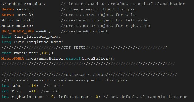
Now that all three stages have been defined, the first step in implementing Mini-Rosco’s firmware is to setup some basic variables and define some objects for motors and servos. This can be seen in the figure below. Since this step is preliminary, it will not be explained and is only being included for the sake of completeness. The only notable variables being created are the ones pertaining to the GPS coordinates and the Ultrasonic sensor.
The next step can be seen in the figure below. In this step we begin incorporating the custom commands that were defined in the ArxR0bot application. It can be seen below that the mode selection command and automated commands are defined using 0x40 and 0x41, respectively. These hex numbers represent their command ID’s that can be found within the ArxRobot application. Then, the command list size must be defined. This is important for identifying how many commands need to be processed.
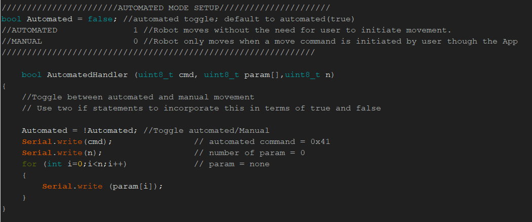
Now that the basic setup has been completed, the first custom command that handles the automated mode toggle can be seen below. While this code may seem simple, it is responsible for the success of two different parts of Mini-Rosco’s mission. As stated above, the automated handler is responsible for ensuring that the Locating mode of Mini-Rosco is done without any user input after GPS coordinates have been entered. It is also responsible for Mini-Rosco’s following capabilities.
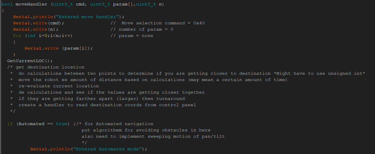
The next step in Mini-Rosco’s firmware is the movehandler shown in the image below. within the move handler, the function called GetCurrentLoc can be seen. This function is vital in the retrieval of the current destination location. It then does a calculation between the destination waypoint and the current location coordinates. If the subtraction of the current location from the destination location gets increasingly smaller as Mini-Rosco moves, then Mini-Rosco is moving in the right direction. If the difference yields a larger number then Mini-Rosco is heading in the wrong direction.
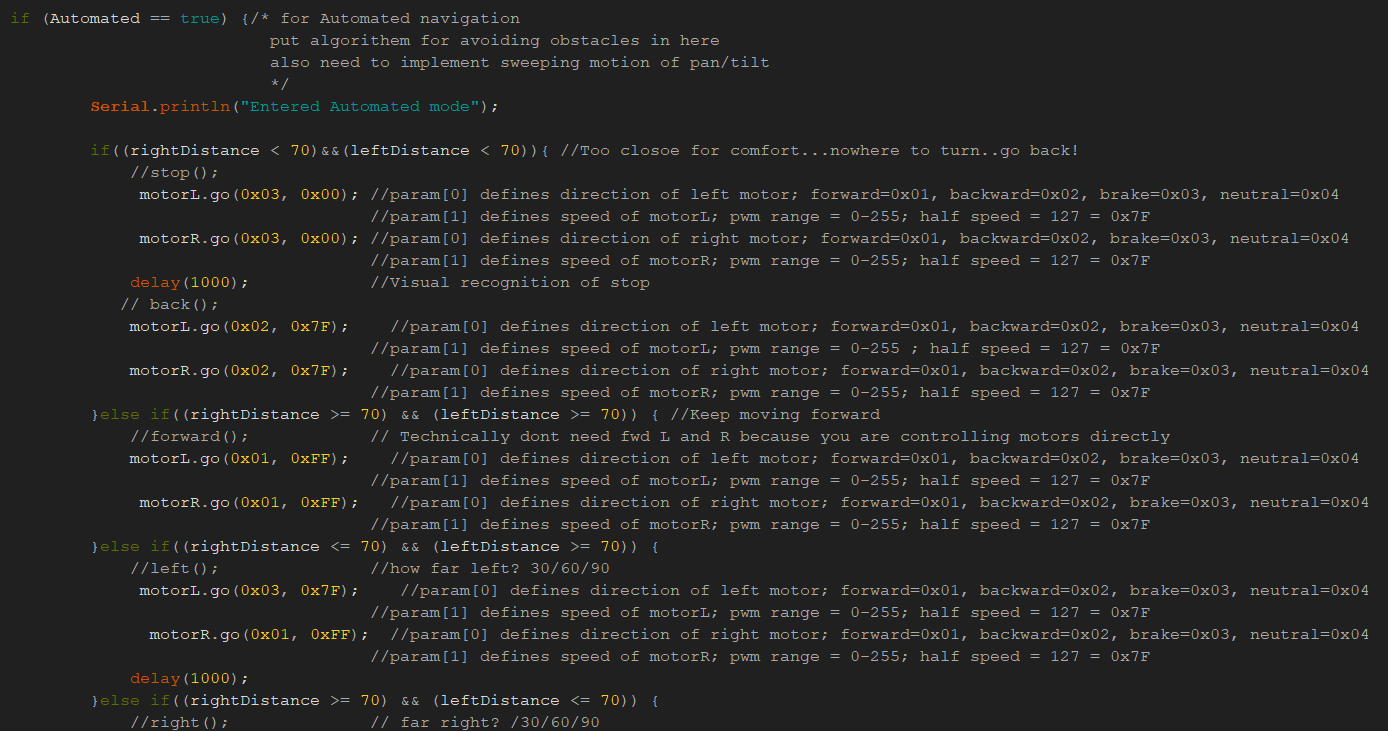
The figure below depicts the logic that occurs when Mini-Rosco attempts to move while in Automated mode. This custom algorithm functions in both the first and third stage of the mission and is explained in greater detail here. Not only does this algorithm cause Mini-Rosco to move towards its destination but it is also built in with obstacle avoidance so that Mini-Rosco can maneuver around obstacles in its path when navigating.
Finally, when automated is off, Mini-Rosco is able to be controlled in RC mode, or remote control mode. The code shown below allows this. Depending on the parameter that is entered through the movement D-pad on the Arxterra control panel, corresponding movements will occur with Mini-Rosco. This code is vital for the second stage of the mission.
Mechanical/Hardware Design
Written by: Darren Chan (Design and Manufacturing)
This section will go over the main parts of Mini-Rosco which are: the chassis, the servo mount, and the ultrasonic holder. The blog posts below will depict the processes and thoughts that went into the designs of each part of our robot. In addition, they will also cover some of the difficulties that we encountered when attempting to build mini-rosco.
Our first part of the robot is the chassis. One of the main goals of Mini-Rosco was to decrease the overall size of the robot while still maintaining the general form factor. In order to do this the main chassis was kept, and a servo tower that resembled the older Rosco servo tower was chosen. To shrink the body of our robot, the chassis was scaled down to around 75 percent of the original value. This value was chosen as a guideline so the group would be able to see how small the robot could be made while still allowing enough surface area to attach the tower and 3dot. As a guideline for how large of a space the new servo tower would need would be, the space originally designated for the servo block was reverted back to its original size. From there the sketch was realigned in order to place the tower position back on the robot. By doing this the group had to remove some of the existing cuts and underlying ridges in order to make room. Looking at the picture below we can see how exactly the sketch in solid works changed when the figure was scaled down and get a better idea of the compromise the group needed to make in order to keep the servo space. Later on the group would find out that the space provided to the servo block was too large for the new tower purchased and so an adjustment to the robot had to be made. The adjustments made were amplified when the group also noticed that the new tower held the servo lower than originally anticipated and so needed to be raised higher than the chassis allowed. The blog post below will go into greater detail on the calculations that went into creating the chassis and the extra piece that was needed in order to compensate for limited printing.
Mini-Rosco Form factor and Adjustment
Once the group decided that we intended to use an ultrasonic sensor in order to implement the following aspect of our robot, the next problem that arose was how to have an ultrasonic that would both be able to move while remaining safe from moving parts. Initially the idea that was proposed was to have a small handle in front of the robot which would hold the ultrasonic and this would be attached to the chassis. However, this idea was scrapped as the ultrasonic has a limited degree of range and having it too low to the ground would limit what it would be able to pick up. Because of this constraint, the group decided that it would be better to have the ultrasonic up higher in order to increase the range in which it would be able to transmit. This led to another hurdle as we now had to decide how to attach ultrasonic at an adequate height. The solution for this problem, was to develop a new attachment that would either hook on or glue to the pan and tilt platform. This would enable the ultrasonic to move when the servo panned which would help the following aspects of the robot. In order to improve aesthetics, screw holes were created for the solid works model to allow easy integration with the pan and tilt model by suing the already existing screw openings on the top art of the tower. The second link goes over the creation and use of the ultrasonic holder. The blog posts cover what went into the creation of our holder such as the measurements which constrained its size, the purpose of the holder, and how to best implement the holder in order to accomplish this purpose. The solid work images of the ultrasonic holder is also included in the blog posts in order to help visualize each change.
Link to Solidworks File
Verification & Validation Test Plan
Written by: Alex Margaris (PM/MST)
Mini-Rosco generation 1 will verify that the implemented design meets all of the functional L1 requirements using the Verification Test Plan. Our execution of the Verification and Validation 0f Mini-Rosco will involve four separate test cases. Each test plan is segmented into steps such that the tester is able to systematically verify each related requirement. In addition, each test case contains detailed success criteria and pre-requisites that aid in determining whether a requirement passes verification. The test cases are labeled: TC-01, TC-02, TC-03, and TC-04. All test cases were performed in Giann’s living room in his apartment.
Test case 1 is a sequence used to verify whether Mini-Rosco’s basic operations meet the requirements. It is important to note that this test case is unrelated to the mission statement and only aims to verify things such as basic movement and functionality.
Test case 2 is a sequence designed to verify requirements related to the assembly, disassembly, and over all visual inspection of Mini-Rosco. Test case 2 also does not relate to the mission.
Test case 3 is a sequence that is used to test the mission operation of Mini-Rosco. Here, Mini-Rosco will execute its mission in steps that have been designed such that multiple requirements can be proven with as few steps as possible.
Test case 4 is unrelated to the physical bot of Mini-Rosco entirely, as Mini-Rosco itself does not need to be present to execute this test case. This test case is used to verify the logistical parameters of Mini-Rosco such as cost and deadline.
Concluding Thoughts and Future Work
Written by: Alex Margaris (PM/MST)
The primary takeaway that our group had with this project is understanding how to generate reasonable requirements in order to complete our mission. Originally, we planned on having Mini-Rosco get another Arxterra robot’s GPS coordinates location, and do calculations to navigate to it. We quickly realized after doing research that this was extremely unreasonable and over complicated to complete in a semester. Unfortunately, we did not realize this until about halfway through the semester, leaving us to scramble (working with Professor Hill and Chris) to come up with another method to implement the GPS PCB that we had already started creating. Some advice for future generations of Mini-Rosco, as well as future generations of other projects, that we would give is to begin planning and ConOps immediately as the semester begins. This will ensure that no design errors or unforeseen constraints and limitations are placed upon your project in later stages of its life cycle.
Some improvements that can be made to Mini-Rosco can be a more complete design of its pan and tilt platform. The current pan and tilt platform is sized for standard servos, while the 3DoT was never intended to power two standard servos at once. One possible solution to this problem is to either redesign the pan and tilt platform to suit micro-servos or to use an external power source other than the 3DoT to power the servos.
Another improvement that can be made to Mini-Rosco is to design a better method of implementing the GPS PCB so that it does not have to utilize the way point system built into the Arxterra platform.
References/Resources
These are the starting resource files for the next generation of robots. All documentation shall be uploaded, linked to, and archived in to the Arxterra Google Drive. The “Resource” section includes links to the following material.
- Project Video
- CDR (N/A)
- PDR
- ProjectLibre Schedule
- Mini-Rosco Verification Test Plan
- Solidworks File
- Fritzing Files Linked to in Electronics Design Blog Post
- EagleCAD files (zip folder) Linked to in Electronics Design Blog Post
- Arduino and/or C++ Code (zip folder) Linked to in Software Design Blog Post
- Mini-Rosco Bill of Materials
- Mechanical Bill of Materials

