Mini-Rosco/Spring/2020
Mini-Rosco: Magnetometer Testing
Author: Giann Carlo C. Bullo
Table of Contents
Introduction
In order for Mini-Rosco to travel to a designated waypoint, it needs to have accurate headings in the x, y, and z coordinates. Without these headings it will be hard for the robot to figure out how to travel to the waypoints made by the user. If the robot does not know which direction it’s pointed, then it will be very difficult for it to know which way to start it’s journey. The robot needs a constant update on its direction so that we can create the quickest route to the waypoint. This has caused the team to test the LSM303DLHC and configure it to act as a compass.
Parts
- LSM303DLHC Accelerometer + Magnetometer Breakout Board
- 3Dot Board
- 4 Jumper Wires
Testing
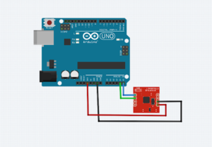
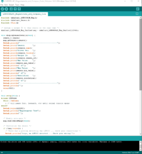
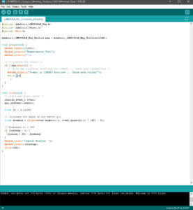
For testing I connected the LSM303DLHC board to the 3Dot using jumper wires. The fritzing above depicts an Uno since fritzing does not have a model for the 3Dot. I then uploaded code to the 3Dot that would calculate the headings based on its orientation. Please note that the method used for calculating the x, y, and z headings was NOT created by Mini-Rosco and all credit goes to Adafruit and as such will not be listed in this blog post to avoid taking credit for another person’s original work. However, the method and algorithm used for waypoints navigation is created by Mini-Rosco. The code in use did not need any changes due to the fact that it was designed specifically for this product. This means that every specification for the board was accounted for so it can be used immediately. Figure 2 represents the code that acquires the x, y, and z values of the board. Figure 3 represents the code that configures these x, y, and z values to compass headings.
Results
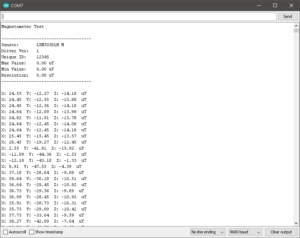
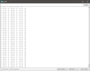
The code needed to be operated in 115200 baud. The values for the current configuration settings are printed on startup, followed by magnetic field readings for the X, Y, and Z axes. The sensor class that was being used from the Adafruit library reports X, Y and Z axis magnetometer readings directly in micro-Teslas. Tesla is the unit of the magnetic induction. The sensor readings reflected the magnetic field of the earth (between 20 and 60 micro-Teslas). By calculating the angle of the magnetic field with respect to the X and Y axis, the device can be used as a compass.
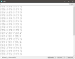
When testing the magnetometer I found that the readings of the axes were heavily skewed when near any strong local magnetic fields. For example, lets look at the two figures below. The first code is a normal reading without any magnetic fields present in the local area. The second however is when I had my phone next to the board and as you can see it affects the boards readings. It starts off at around 13/14 uT in the x axes. As my phone approaches the board the x axes drops all the way to 9 uT and goes back up after my phone leaves its vicinity. This test has confirmed that the board should not be close to the GPS module or its readings will get affected which will ultimately affect our waypoint navigation. The teams needs to find a place for the compass on the robot where it will not be affected by the ultrasonic sensor, 3Dot, or customized PCB.
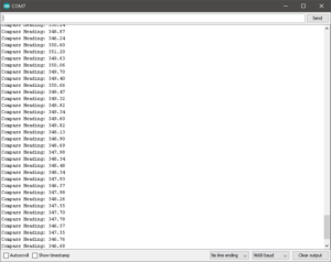
Finally we convert the micro-Tesla readings into a 0-360 degree compass heading by using the atan2() function to compute the angle of the vector defined by the Y and X axis readings. The result will be in radians, so we multiply by 180 degrees and divide by Pi to convert that to degrees. I compared the readings to my phone’s compass which was pretty accurate in its readings.
Conclusion
In conclusion, Mini-Rosco utilizes a magnetometer that will be configured into a compass to give accurate readings of Mini-Rosco’s headings as it moves. The testing of the magnetometer has proven to be successful and gives us insight as to the placing of components on the robot and in the completion of Mini-Rosco’s Mission.

