MiniRosco/Spring/2020
Mini-Rosco Ultrasonic Mount
Author/s: Darren Chan – Manufacturing
Table of Contents
Introduction
It was proposed that instead of the ultrasonic (Us 100 ultrasonic) being stationary and fixed to the front of the robot, we would instead have the ultrasonic be able to turn when the servos moved. In order to accomplish this a new addition had to be made to the robot in order to attach this new mount to the moving portion of the servo.
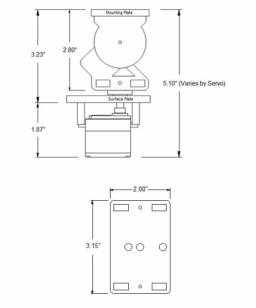
The area that I decided to attach this new piece to is the circular plate which holds the mounting plate that would be used to hold our phones. This region was selected as this piece would be able to both rotate and rise should the movement of the servo require it. In addition, the area on top of the servo mounting plate was also considered, however due to the dimensions of the phone that would need to sit on top of the upper mounting plate this idea was scrapped as it left no room for an arm to be created.
Measurements
As the website for the pan and tilt platform did not have more specific dimensions on the circular plate, hand measurements had to be taken in order to ensure that the new addition to the piece would be able to fit while still carrying our ultrasonic. In addition, this piece would need to go low enough to clear an average-sized phone which would be attached to the front of the mounting plate.
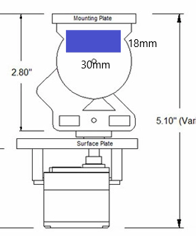
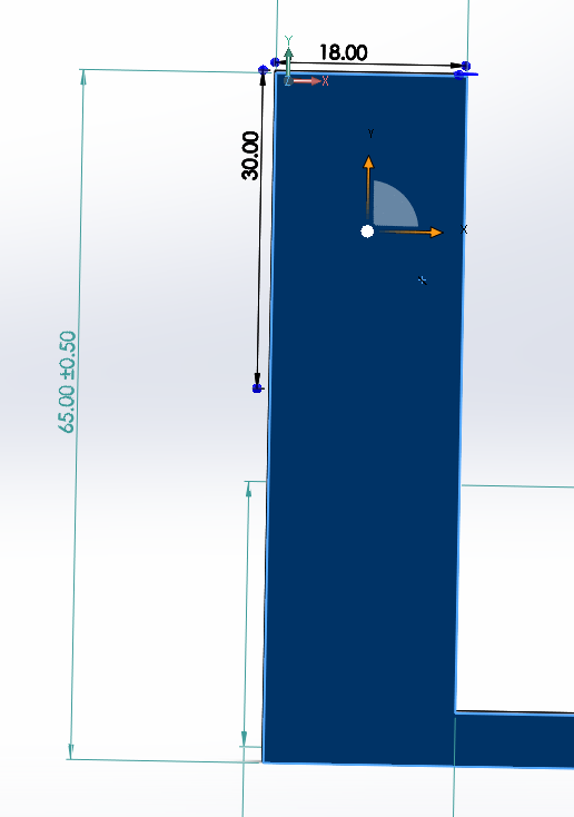
Shown below are the measurements that were decided for the base that would up our ultrasonic. This region was chosen as it would be allowed for the most surface area free from the screws. As this pan and tilt model was purchased instead of built, it was not possible to edit the design and so I had to work around it. The side is shown in the picture above also only possessed one screw while the other side possessed 4 which took up more surface area which would have given us less space to apply and adhesive. As I was unsure of the final weight of the ultrasonic I attempted to give a larger area for our adhesive to stick onto. The area chosen was an 18mm by 30mm surface area.
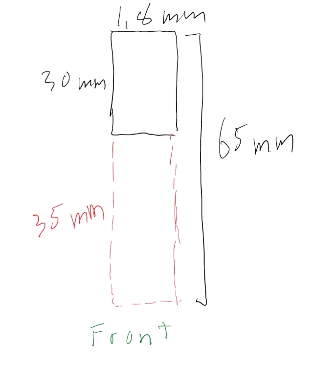
Once our adhesion point was created, the next part that had to be accounted for was how far down the arm needed to go in order to clear the phone, while also remaining above our surface plate level. As we can see from the above picture, we have a space of around 3.23 inches (82 millimeters) to work with. Based on this space I decided for a length extension of 35mm (65mm total) as it will be able to clear our mounting plate, while also giving the ultrasonic the ability to tilt down without pushing against the surface plate should the servo tilt down. Shown below is the drawing with measurements of what will be implemented into solid works.
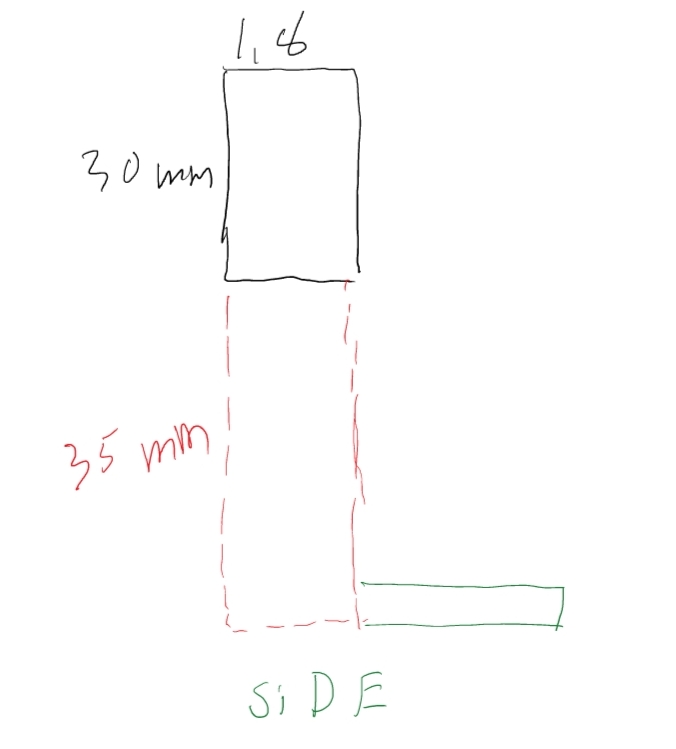
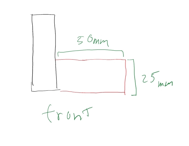
Once the arm portion of the servo was calculated for, the next measurement involved the connecting region of the platform that the ultrasonic would sit on. Measuring by hand I determined that an optimal extension distance would be around 35mm as it would allow for the ultrasonic to sit in front of the phone plate. This region is marked in green below. A longer region wasn’t selected as one of the goals of this project was to decrease the size of the Rosco, and having a portion of the robot extend to much to the front would defeat this goal. The reason why a closer range wasn’t chosen, was due to the fact that some room for errors had to be taken into account should the attachment of the arm prove to be to close to the phone.
Once the extension was measured out we needed the actual dock that the ultrasonic would sit on. Our ultrasonic has a size of 20mm by 45 mm, so the dock was measured to fit this distance. In addition, part of the 25mm would be taken up by the “seat” which is shown above. This would mean I would only need to create a rise of 20mm instead of 25mm. These values were chosen based on the ultrasonic specification, and also so that I could create a little holder for the board to just slide into.
Solid Works
Once the measurements of the arm were completed the next part involved creating the model in solid works. As I was not editing a model but creating it from scratch I was able to design it in a way I decided was the easiest. More specifically I used multiple sketches of rectangles and squares in order to create the sketches I wanted with the set parameters.
The first part that needed to be created was the base for the adhesive. As stated before this piece would be 18mm by 30mm. A rectangle was created, and by using the ‘smart dimension’ tool in solid works the lengths were adjusted in order to create the desired perimeter. Once this was accomplished, I extruded the piece in order to make it more than a plane. I chose an extrusion value of 10mm. This was done by selecting the sketch of the rectangle and then extruding it outwards. Using this extrusion as a base, I made a new sketch on the bottom of the piece and extruded the arm downwards. Since our adhesive peice was already at 30mm I needed to only extrude an additional 35mm. This is shown below. In addition, once these pieces were extruded I needed to add the part that would extend outwards. Using the measurements I made, I created a new sketch along the base of the previous extrusion, with length at 10mm and height at 5mm. Then I pulled this area out 35mm from the previous piece. Once this was finished I had the completed arm for my holder.
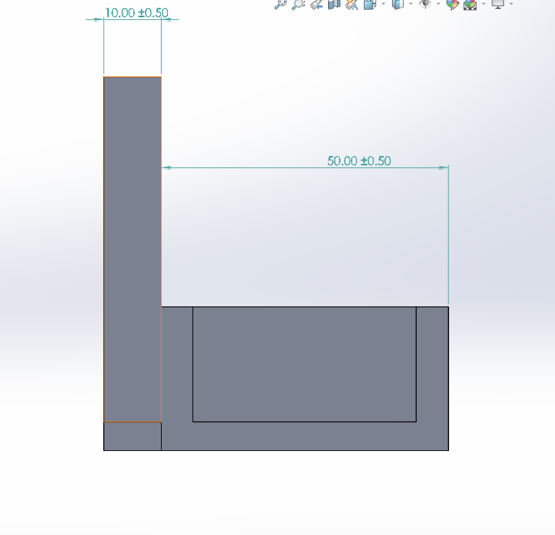
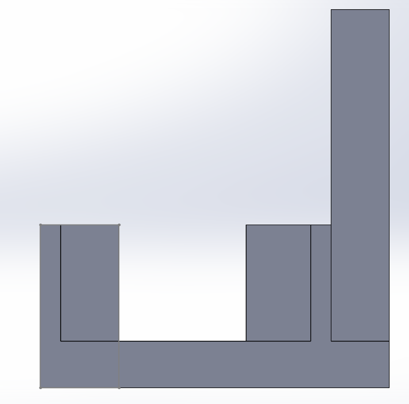
The next part of this piece involved the holder that the ultrasonic would lay upon. A new sketch was made with a length of 50mm and a width of 25mm including the base of the arm extension. As I did not want to apply an adhesive to the ultrasonic, I designed a way for the electronic to just slide into the new piece that I made. In order to accomplish this, I used the previous sketch and extruded it 10mm forward in order to create a block that I would be able to work with. The next portion involves cutting away pieces of this block in order to create a space for the ultrasonic to slide into. From the front, I used the cut tool available in solid works and cut out a sketch I had created. This cut would cut 5mm into our 10mm rectangle while leaving the sides intact. This cut is needed in order to fit the devices that are present in front of the ultrasonic. As I did not have the ultrasonic on hand, I had to give a lot of error room to how much space these pieces would take up.
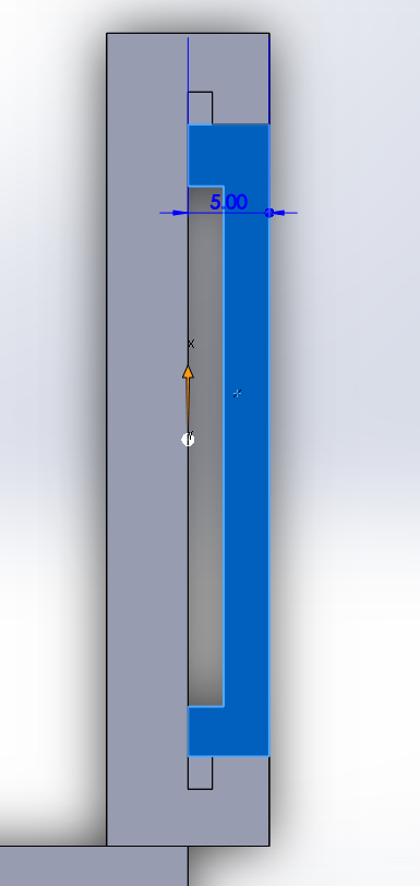
Once the main cut was done, what was required was a variety of smaller cuts that would be used to house the board along with making room for the pins that need to be attached. Shown below is the first draft of what was created in order to house the board. The main cut created in the center was originally for the pins as I believed that they extended from the bottom of the board. A sketch was made with a cut that extended out of the board. While the width of the sketch was 5mm, the value of the cut is irrelevant as long as there is an opening. The smaller squares on the side were created in order to allow the board to slide into the opening. As the board is 20mm downwards, these cuts needed to reflect this in order to allow the board to reach the bottom so the cut for the pins could be used.
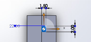
The smaller cuts for sliding the board into place were created based on estimations from the dimensions of our board. As the thickness of the board wasn’t specified an estimation was made with some room for error. The reason being is that if the opening was a little big the board would still be able to sit, however, if the opening was too small then the board would not be able to enter. The sketch for this was two identical rectangles at 1.5mm (w) and 2mm (L). The reason why two smaller squares needed to be made was due to the fact that when I created the first major cut I was unable to extend the back portion so I had to add on a new sketch. These little cuts which would extend downwards 20mm would be used to hold our board in place.
In Assembly
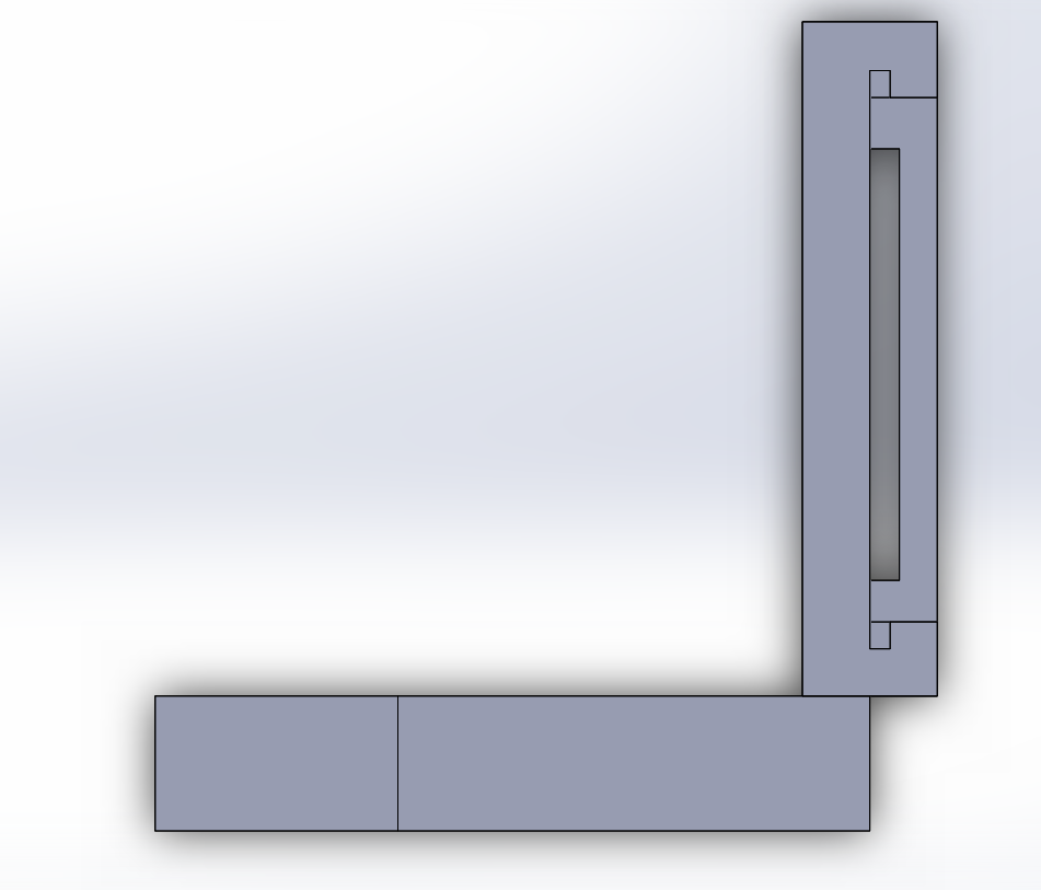
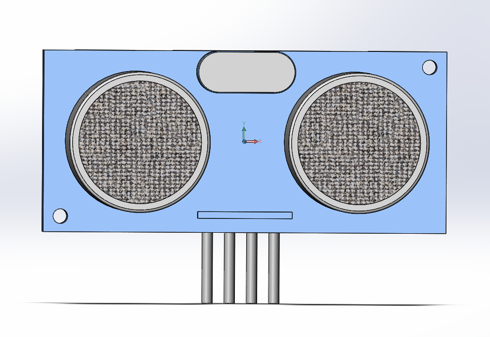
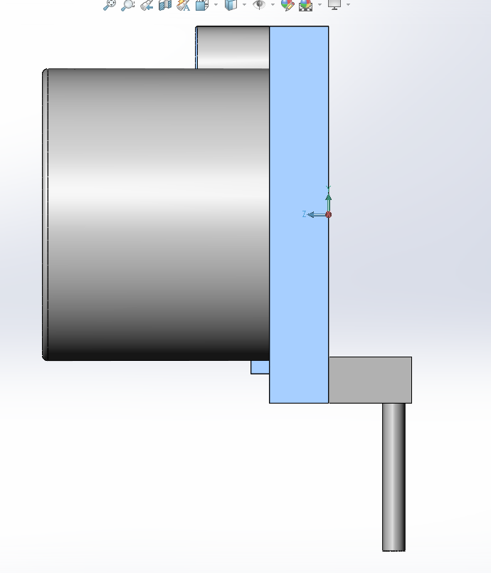
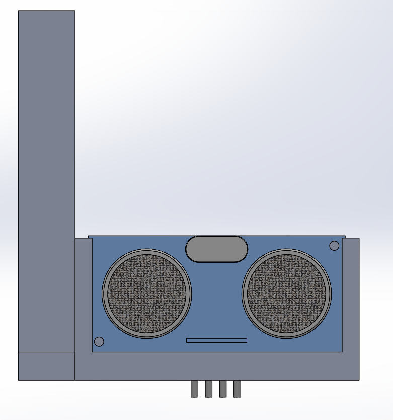
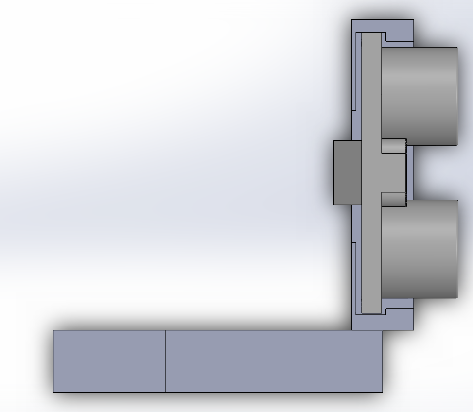
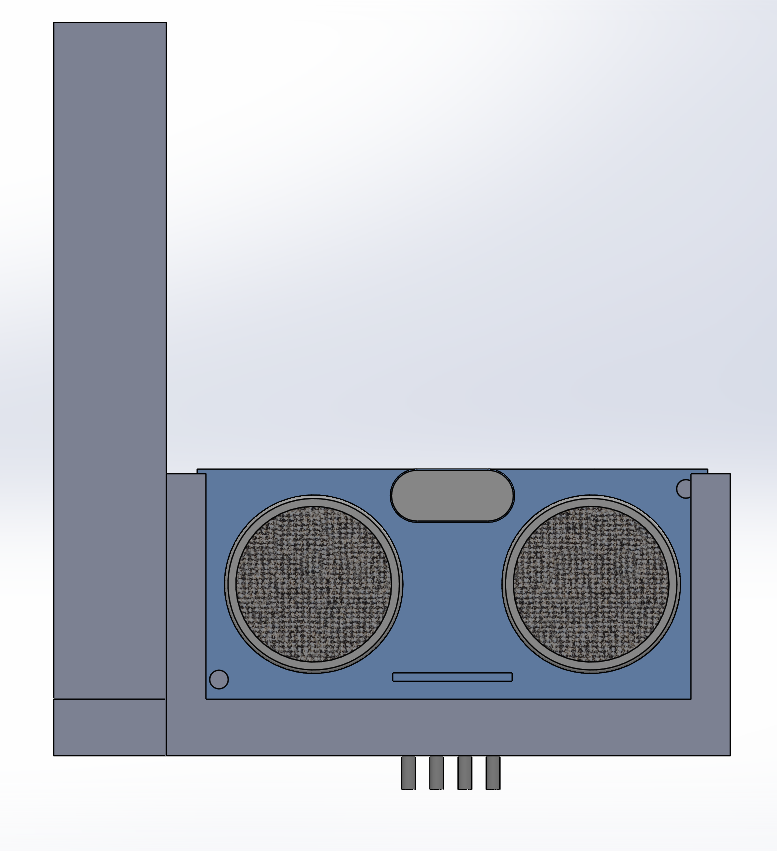
Once the solid works files had been completed there were converted into an assembly in order to test how they would work once a virtual ultrasonic was place inside. As I was using the dimensions of an ultrasonic, it was possible to have miscalculated a parameter when making my holder. In order to combat this, an “ultrasonic” was downloaded off a public website. This would allow me to place this ultrasonic in the holder and see if what I envisioned was correct. This was actually very useful for testing as they allowed me to see the errors with my previous design. The link for the solid works file of the ultrasonic is placed below.
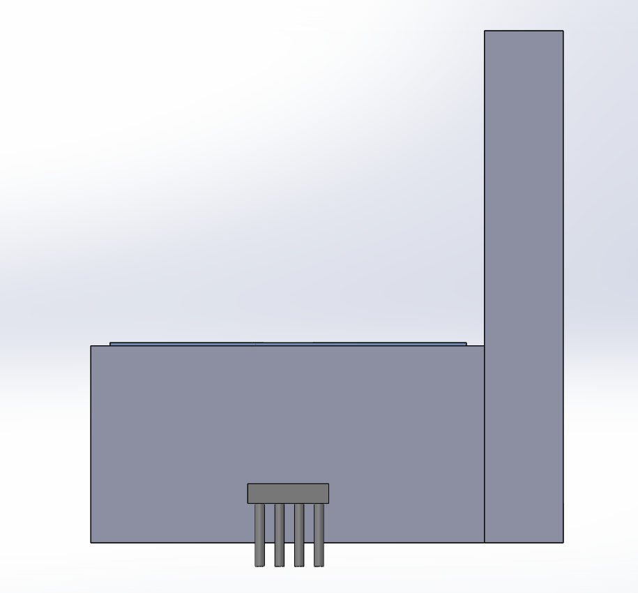
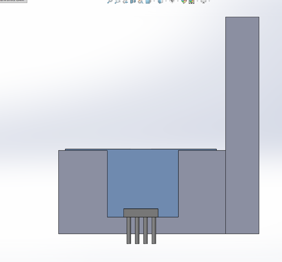
Looking at the assembly file we can see that there was an error in where I believed the pins would go, and so this would need to be corrected in the next version. More specifically a cut would need to be made in the back panel that would allow for the pins to clear the space.
Corrections
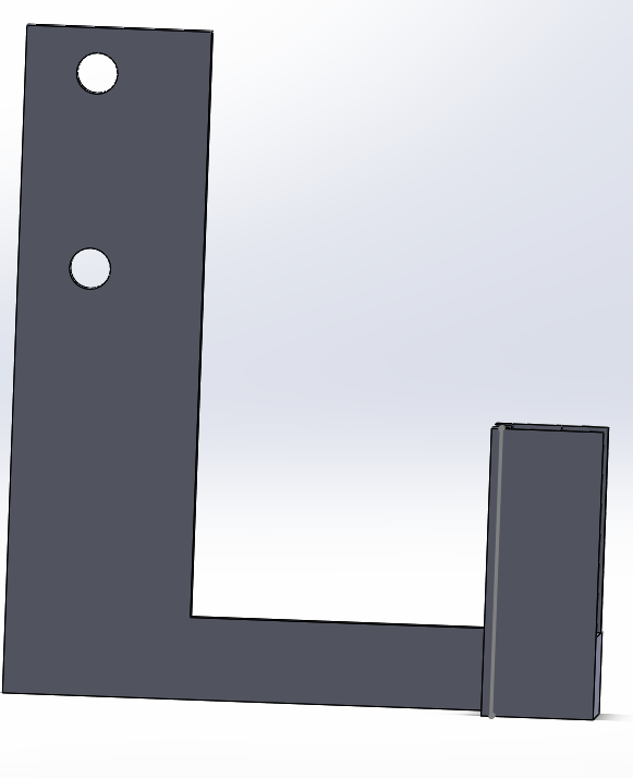
For the corrections, instead of a cut made in the base of the holder, a new cut was created in the back in order for the pins to rest outside of the mount. In addition, the walls of the holder were also extended in order to account for the 3d printer that was being used. More specifically the back walls were extended to be 4mm.
In addition, in order to allow more seamless integration of the ultrasonic holder, cut extrudes were made on the side of the arm that would attach to the pan and tilt. The arm was then moved to the adjacent side in order to make use of the screws that were available on the side of the pan and tilt platform. As we would be using the same screws as those provided for the pan and tilt, I measured out the diameter of the screws which amounted to 4mm. Using this measurement I made two cuts into the side of the holder. As the measurements all had to be done by hand the distance of the two holes did not perfectly align with the hole locations. However, this was not a major issue as only one screw was needed to apply the design. It should be noted that some leeway should be given when designing the cuts in order to account for errors. Too large of screw holes can be fixed by implementing a washer.
Conclusion
The ultrasonic holder was made to serve the purpose of allowing the ultrasonic to move with the camera. As there was no object on the robot with the ability to move besides the servo, this is were the holder would find itself. Utilizing the screws on the side of the pan/tilt platform the holder would be able to rotate when the phone was moved. By allowing the ultrasonic holder to be screwed into the side of the pan and tilt allowed for a more seamless integration.

