ModWheels #3 modeling our system and electric differential slip system
Modwheels/spring/2020
modeling our system and electric differential slip
Author/s: Israel Mejia (mission, systems and test)
Table of Contents
Introduction
Mod Wheels #3 is the next generation in which a turbo boost will be implemented to make our car make a loop de loop. Mod wheels will also contain an electrical differential slip system in order to correctly maneuver our vehicle. In order to achieve these two objectives we must find a way to model our system. Once we get a model of our system we will have a better idea of how these objectives will be achieved.
Rpm and torque
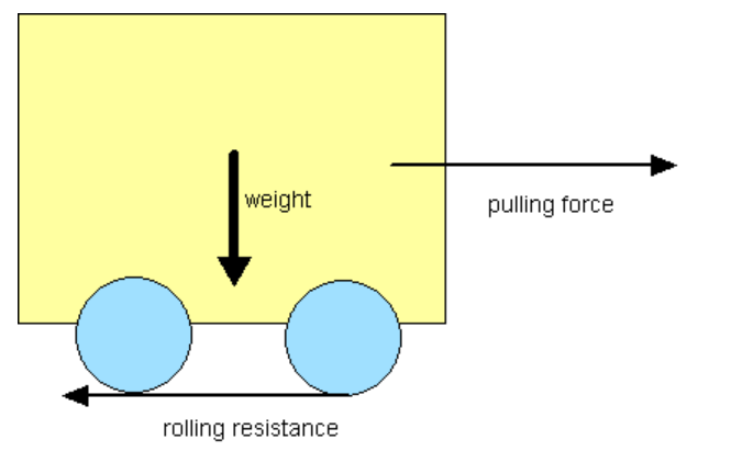
We need to set up a coefficient of friction in order to correctly model our problem. From what we know Newton’s first law an object will not change in its velocity unless there is an external force acting on it. We need this or else the model will seem to go forever. This can be very difficult though we can look up a list of possible coefficients. The coefficients above have satisfactory values that can apply to our model. As we can see, hard rubber on concrete coefficient of Friction for a wheel size 5CM in radius is in between 0.2- 0.4 . In our first model we have a 2.1cm radius wheel and in our final model we have 3cm radius wheels. We will go for the worst case scenario for our friction.
So C=.4 M=200g D1=4.2cm D2=6cm
Rolling friction
Fr=C*N where C is the coefficient of friction and N is the normal force(weight)
N=M*g where M is the total mass and g is acceleration of gravity
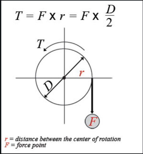
If we want to know the Torque needed to move against this force of friction. We take the radius of the wheel and multiply by force.
T=Fr*D/2
Torque will then be divided by 2 since we will have two motors that will handle this torque
T/2=Torque per motor
In order to find the appropriate motor Rpm we need to know what speed we need to achieve. We are looking at a one foot loop. This can be done at a speed of 1.2m/s. Now what is the RMP?
V=r*w velocity equal to radius times angular velocity
1rad/s=60/(2*pi)rpm rad to rpm
r=D/2
(V*2/D)*(60/(2*pi))=rpm
60*V/(pi*D)=rpm
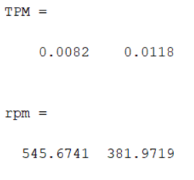
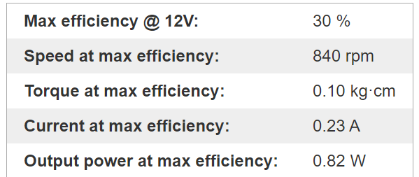
TPM is torque per motor as we can see the torque needed to move our car with our old tires and new tires. As well as the rpms needed to achieve the desired loop. Since our new tires are larger in diameter they need more torque but the trade off is that we need a lower rpm. Another thing we can consider if we take a look at the coefficient of rolling friction as the wheel diameter grows the coefficient of rolling friction goes down as well which is another benefit of going with larger wheels. Our new motors can reach speed of 840 rpm with a torque of .009N*m (.1kg*cm) at 12 v slightly lower than the desired .0118N*m but we make up for it in speed.
RPM measurments
For this lab we need to have the following
Equipment:
- Matlab
- Excel
- Tachometer
- Multimeter
- 30:1 motors + wheel
- 3dot
- Arxterrra app
- Measuring tape
We can measure the rpm values of the motors using our tachometer. The motor speed can easily be changed by making a custom Arxterra command using an unsigned byte and adjusting the motor speed at will. we can then measure the output voltage using a multimeter.
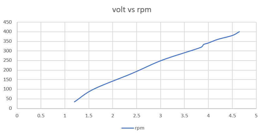
This is a graph of voltage vs rpm. From the chart, we can see the command sent the voltage and rpm value related to it. We need a minimum of 1.2v in order not to stall our motors. We can see that it is basically linear for these low voltage values and increases 100rpms per volt.
Differential drive
This is the model used in order to find the differential drive rpm values. This model is used for values in the hundreds of rpm’s so it is a good fit to model our system .
Matlab is used to map out the rpms of the inner and outer wheel depending on steering angle and desired rpm outcome. It can be kept in mind only one side needs to be calculated and calculations can be mirrored for negative steering angle (left). The values needed to be measured are L=8.5cm distance from front to back wheels. dr=10.5cm distance rear wheels are from each other and Lr=3cm distance from rear wheel and the center of gravity.
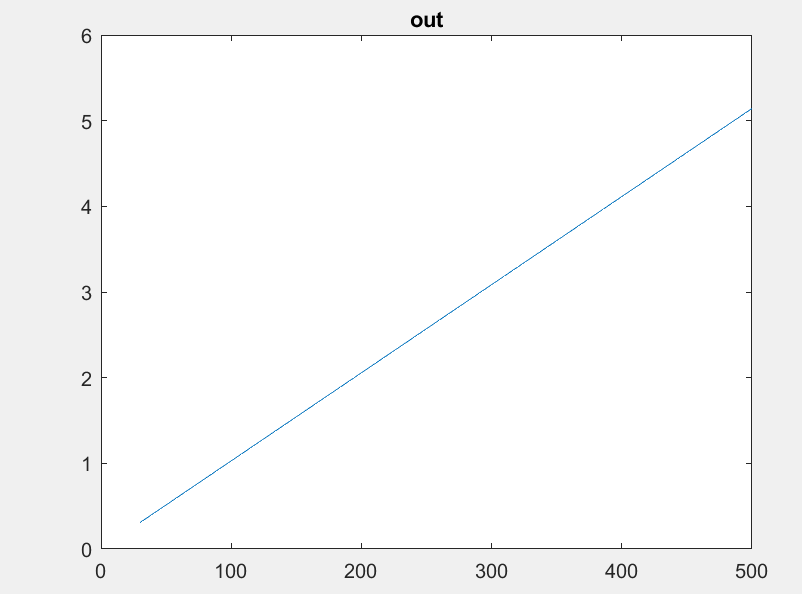
I range our rpm from 0 to 500 at a steering angle or 1. Here we see the change in rpm depending on rpm so as we can see increasing our speed the outer wheel will need to go faster while the inner wheel starts to decrease so at a desired 500rpm speed at an angle of 1 we will need the outer wheel at 505rpm and inner wheel at 495rpm .
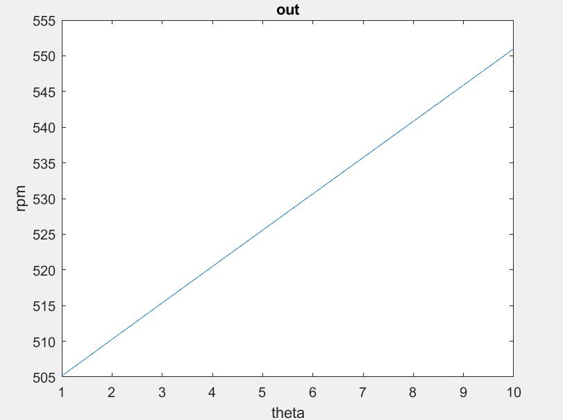
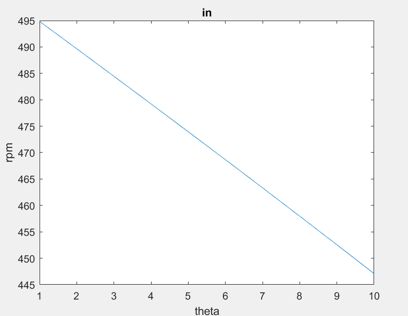
Similarly, we can see how the angle of theta will affect rpm values. As we increase the angle of theta our outer wheel will need to spin faster as our inner wheel will decrease in speed. Desired rpm and angle of theta will be the two variables that will govern the differential drive system.
Encoders
Now that we have a good model for our system we can look at the hardware to be used in order to get the differential drive working. In order to have a working differential drive we need to get come shaft encoders. For this we have a couple options.
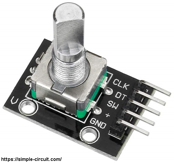
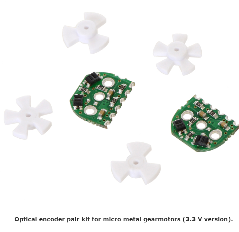
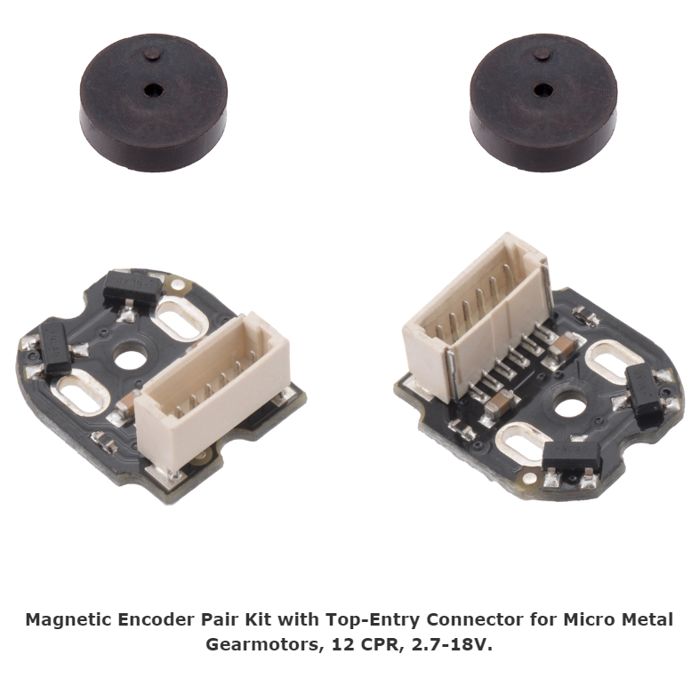
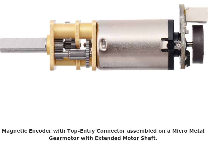
We have an option of a rotary encoder, optical encoder, and hall effect encoder. The rotary encoder is alot bigger and takes up more space in the pcb. So our options are the optical or magnetic hall effect encoders. For our application we went with the hall encoder due to the smaller size and more accurate reading compared to the optical encoder that has been known to have error the hall effect sensor can more accurately sense change in magnets’ polarity
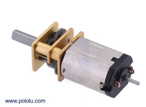
These encoders are to be soldered on to micro gearmotors with dual shaft.
With these encoders we can now read each motor’s rpm and adjust the values accordingly. In order to make the slip part of our differential and make best of our encoder we can make a feedback loop and use a PID controller to make sure the rpm values are set at the correct values.
Conclusion
Now that we have modeled our system the objective seems more realizable. We can now take the model we have created and implement it into the hardware and software of the system
References/Resources
LINK to mod wheels code
https://drive.google.com/drive/folders/1xGkU_L00A8Xeqk3eG99_HixW185z2VP9
References
1.https://www.engineeringtoolbox.com/rolling-friction-resistance-d_1303.html
2.https://www.google.com/url?sa=i&url=https%3A%2F%2Faisdblend.instructure.com%2Fcourses%2F60856%2Ffiles%2F1800002%2Fdownload%3Fwrap%3D1&psig=AOvVaw1ILKsLwjsSlKWphM7Kf9oR&ust=1589131522970000&source=images&cd=vfe&ved=0CAMQjB1qFwoTCKC5-rKmp-kCFQAAAAAdAAAAABAD
3.https://www.orientalmotor.com/technology/motor-sizing-calculations.html
4.https://www.researchgate.net/publication/304413848_Electronic_differential_system_for_an_electric_vehicle_with_in-wheel_motorhttps://
5.www.addicore.com/rotary-encoder-knob-p/ad267.htmhttps://
6,www.pololu.com/


