ModWheels Fall 2019
Custom PCB
Author/s: David Zhou
Verification:
Approval:
Table of Contents
Introduction
The custom PCB for the second generation of ModWheels will incorporate a LM386 audio amplifier as well as a TCA9534A 8-bit I2C I/O expander chip that will control the LEDs used for the headlights and turn signals as well as the inputs from the shaft encoders of the metal gear motors used.
Schematic
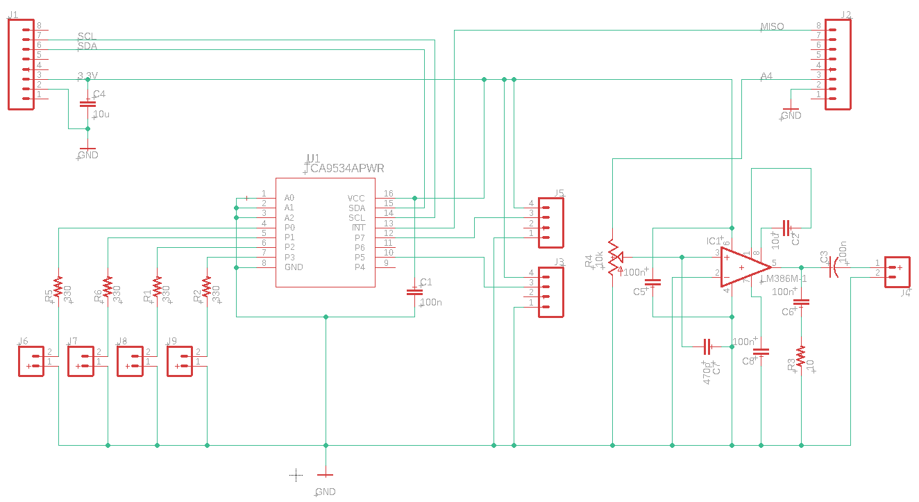
This is the schematic of the printed circuit board that was created using EagleCAD. The PCB uses two 8-pin headers found from the sparkfun EagleCAD library. The only pins we will be usng for the PCB are SDA, SCL, GND, 3.3v, MISO, and A4. There is a 10 uF capacitor denoted as C4 across the 3.3V and GND in order to reduce the about of noise. Similarly, there are 100 nF decoupling capacitors across the voltage source input of each IC chip. These resistors are denoted as C1 and C5.
Audio Amplifier Circuit
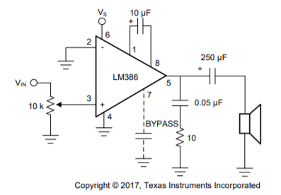
The audio amplifier used is based on the circuit provided by the Texas Instrument data sheet. This audio amplifier was chosen since it can produce a gain of up to 200. Some changes to the circuit that was made is the capacitor at pin 5. The .05 uF capacitor as well as the 250 uF were changed to a 100 nF capacitor. The 250 uF was able to be reduced to a 100 nF since the 3DoT does not produce a lot of current. The use of the 100 nF capacitor has been verified through breadboard testing. Another change that was added to the circuit was a 470 pF capacitor across the pin 3 input and ground. This resistor was added to prevent radio interference to the circuit. The idea of adding this resistor is based on the circuit used by Circuit Basics.
I2C Implementation
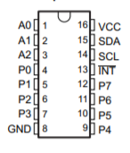
The I2C chip is used to create more I/O ports for the circuit. The SDA and SCL pins are connected to the SDA and SCL pins of the 3DoT. The LEDs are connected to pins P0, P1, P2, and P3 and are configured as outputs. P7 and P5 are configured as the inputs for the encoder and the output interrupt pin is connected to MISO of the 3DoT. The interrupt output pin will be triggered when there is a change from the encoders. A1, A2, and A3 are set to ground in order order to define the hex address to call the I2C.
When writing an input the hex address 0x38 is used. After calling the address, we need to define which pins to output to followed by the value that is being sent. We are able to read an input for the chip by following a similar procedure. In order to read an input we use hex address 0x39. After specifying that we will be reading an input, we define which pins we will be reading from.
Issues with the PCB
The initial print of the board also uses a different footprint for the potentiometer. The newer version of the PCB changes this footprint to match that of a trim pot. Another change made to the newer version of the PCB is the 1000 uF capacitor has been changed to a surface mount capacitor with a value of 100 nF. This is due to the fact that the 3DoT does not generate enough current for the use of a 1000 uF. Although the built in current limiter does protect the 3DoT board from damage due to surge currents, the use of a higher capacitor does present the possibility damage due to higher currents.
Conclusion
The purpose of the PCB is to fulfill the requirements of having a speaker and LEDs for the headlights and the turn signals. Testing of these circuits have been done through breadboarding before fabrication. The LEDs and speakers are functioning and working properly though the PCB using inputs from the 3DoT.


