ModWheels Mock-up with Motor Specific Testing
By: Matt Shellhammer (Electronics & Control Engineer)
Approved by: Lucas Gutierrez (Project Manager)
Table of Contents
Introduction
When working with a 3DoT board we need to know the amount of current and power that all peripheral devices will be drawing. This is something that is very important for mission success and if we do not have enough power to complete the mission we will have to come up with alternate solutions to developing a successful power budget.
Methodology
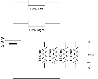
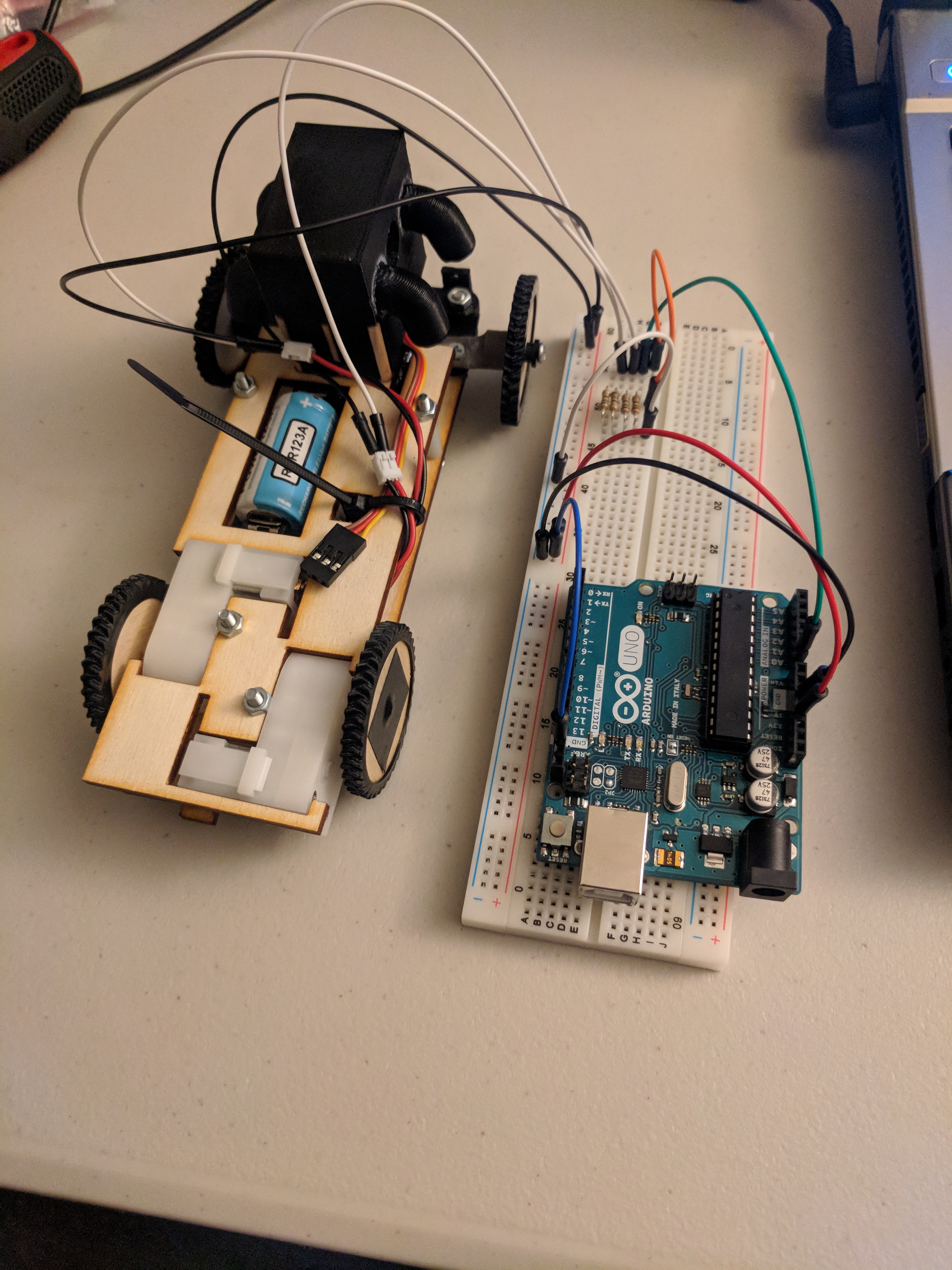
In this motor specific test I will be testing the current draw of the two GM6 motors for the ModWheels car. The way this test was performed was using an Arduino Uno as a power supply for the two GM6 motors as well as a device for recording the voltage drop across a parallel combination of resistors. To measure the current drawn by the two GM6 motors I used the configuration shown in Figure 1 with two GM6 motors in parallel and then four 15 Ω resistors in parallel to create a small resistance (3.75 Ω) to measure the voltage across. To record the voltage across the resistors an analog pin on the Arduino Uno was used to read the voltage and then print that voltage into the Arduino serial monitor. Once the samples were recorded in the serial monitor I then copied those samples into a MATLAB matrix to plot the results. I ran this test for two cases; the first case was with no load (rear wheels removed) shown in Figure 2, and the second case was the full ModWheels load shown in Figure 3. The second case with the full load was performed with the help of another person to assist holding the breadboard while the car is driving straight.
Figure 1. ModWheels motor current draw test setup
Figure 2. ModWheels motor current draw test setup for no load
Figure 3. ModWheels motor current draw test setup for full load
Results
Both tests were ran for thirty seconds recording approximately 6500 samples each. The results were plotted in MATLAB shown in Figures 4 & 5. The average current in case one with no load was 182.43 mA and the average current in case two with full load was 190.74 mA.
Figure 4. ModWheels unloaded current draw MATLAB plot
Figure 5. ModWheels loaded current draw MATLAB plot
Software
To convert the digital input from a quantized value to an analog value the following equation was used:
The reference voltage was 3.3 volts using the AREF external reference voltage pin on the Arduino Uno. The samples were then divided by the parallel resistance to obtain the current drawn by the two GM6 motors and plotted in MATLAB.
Arduino:
////////////////////////////////////////////////////////////////
//  Name     : Motor Test using Arduino Uno                   //
//  Author   : Matt Shellhammer                               //
//  Date     : 28 November, 2017                              //
//  Version  : 1.0                                            //
////////////////////////////////////////////////////////////////

void setup(){
  Serial.begin(9600);
  // Set the PIN Mode
  pinMode(A0, INPUT);
  // Set Analog reference to AREF
  analogReference(EXTERNAL);
  delay(5000);
}

void loop(){
  float V = 3.3*analogRead(A0)/1023;
  Serial.print(V);Serial.print("\t");
}
MATLAB:
%% Motor Test Plots
clear,clc,close all
%%% Resistance: Four 15 Ohms resistors in parallel = 3.75 Ohms (Measured:
%%% 4.7 Ohms)
R = 4.7;
load('motortestdata.mat')
% Unloaded current (recoreded over 30 second interval)
unloaded_I = (unloaded_V./R)*1000; % Result is in mA
AvgUnloaded_I = smooth(unloaded_I, 0.1,'loess')';
avg_unloadedI = mean(unloaded_I);
figure(1)
plot(unloaded_I,'o','MarkerSize',5)
grid on;hold on
plot(AvgUnloaded_I,'r','linewidth',4)
title('ModWheels unloaded current draw')
ylabel('Current (mA)')
xlabel('Sample')
axis([1 6353 0 300])

loaded_I = (loaded_V./R)*1000; % Result is in mA
AvgLoaded_I = smooth(loaded_I, 0.1,'loess')';
avg_loadedI = mean(loaded_I);
figure(2)
plot(loaded_I,'o','MarkerSize',5)
grid on;hold on
plot(AvgLoaded_I,'r','linewidth',4)
title('ModWheels loaded current draw')
ylabel('Current (mA)')
xlabel('Sample')
axis([1 6543 0 300])


