ModWheels Servo Test
By: Andrew Yi (Mission, Systems, & Test Engineer)
Approved by: Lucas Gutierrez (Project Manager)
Table of Contents
Introduction
Servos are notorious for drawing large amounts of current and needs to be taken into account when using the v5.03 3DoT Board. The servo pulls its power directly from the battery via the servo headers on the 3DoT Board. This test will measure the current draw of the servo in different settings:
- -45 degrees to +45 degrees constant turning (worst case scenario)
- -10 degrees to +10 degrees constant turning (average case scenario)
- Idle current
During its navigation within the maze, ModWheels will be performing small adjustments to keep itself within the confines of the maze hallways. This is the justification for test #2. This test should pull the most current because of how servos work. Servos encase a small DC motor that provides high RPM and low torque. The mini gears allow the servo arm to swing at a lower speed, but provide a higher amount of torque.
Test Setup
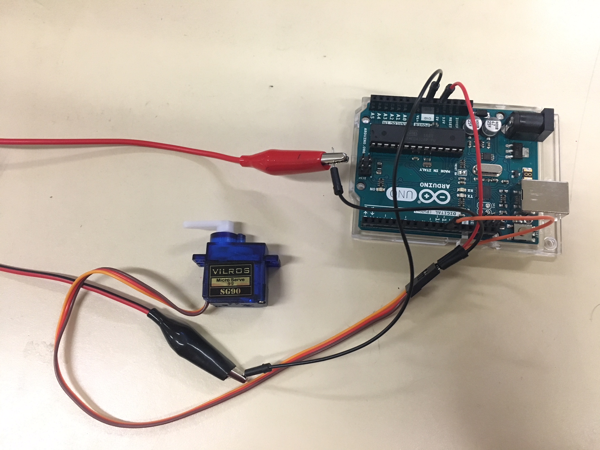
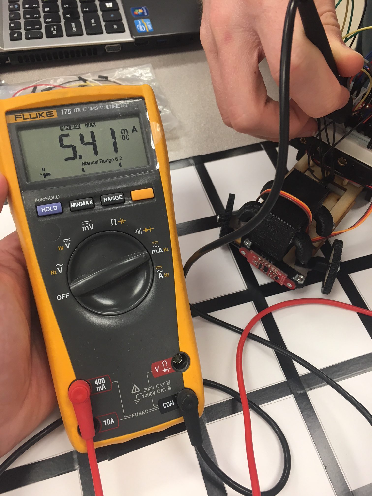
A handheld digital multi-meter (DMM) was connected in series with the ground wire to test the current draw during these tests. These tests give an overview of the current being drawn and allow us to have an idea of the amount of current being drawn. More in depth tests will follow.
Figure 1: Test Setup
Test Values
The following values are for each test with the DMML:
Test 1:
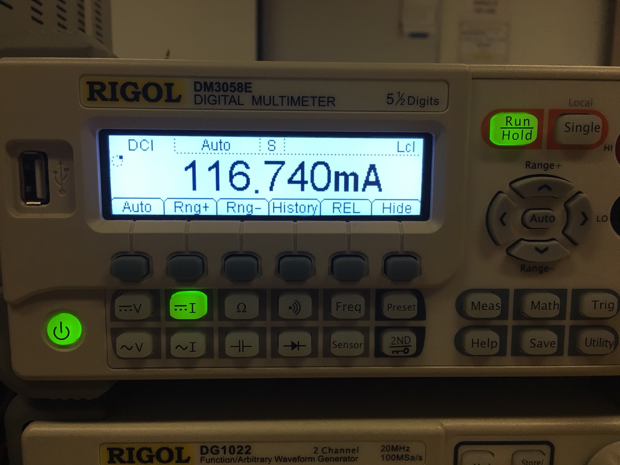
The servo was programmed to constantly shift from -45 degrees to +45 degrees. This test is to check that our power isn’t adversely affected if the ModWheels toy car were to find itself in this situation (constant turning). Wide turns should not pull as much current because of the rate of change being less frequent (compared to test #2).

Figure 2: Test 1
Test 2:
This is the test for the ModWheels’ “worst-case” current draw. Since ModWheels will spend most of its time within hallways, the servo will be making small adjustments to make sure the parameters (distance from hedges) are met. Since the servo arm will be going from -10 to +10 degrees at a rapid rate, the highest amount of current draw should be from this scenario.

Figure 3: Test 2
Test 3:
The idle current is tested to see how much current is drawn when there are no commands being sent to the servo. This test is to ensure that the servo does not have issues during idle mode. What we don’t want to see are sudden spikes in current draw when the servo isn’t receiving any commands.
Figure 4: Test 3
Conclusion:
Judging from the worst case scenario (Test #2), ModWheels should not have power issues with the servo, as it draws directly from the battery. The current draw from the servo was set at 250mA because of the addition of load in the final toy robot.


