Motor Selection
By: Electronics and Control – Kevin Armentrout
Table of Contents
Motor Selection
Motor Selection Criteria
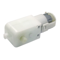
From our initial calculations in PDR, it was determined that a motor must be able to produce a minimum of 140 mN-m of torque to provide the necessary movement for the legs of the raptor. This requirement initially left us with only one option, the Tamiya 70168 gearbox motor. More research, however, uncovered another candidate for our motor selection, the GM-9 Right angle motor.
Side by side comparison with tested values:
| Motor | Speed | INL | IStall | IAve | Stall Torque | Weight |
| Tamiya 70168 | 36 RPM | 163 mA | 2056 mA | 763 mA | 223 mN-m | 160g |
| GM-9 RA | 40 RPM | 55 mA | 461 mA | 146 mA | 311 mN-m | 30g |
As seen by this comparison, the GM-9 Right Angle outclassed the Tamiya 70168 in every category. In addition to this, the GM-9 Right angle also supports a voltage range from 3-6V, which will allow for the entire voltage range of the battery from 3.6V to 4.2V
Graph of Current Versus Leg Position

Source Code
Battery Analysis
| legMaxTorque = .223
legMaxTorque2 = .311 legCurrent2 = .055 + (.461 – .055) * TorqueForCurrent/(legMaxTorque2) legCurrent = .15 + (2.1 – .15) * TorqueForCurrent/(legMaxTorque) legAveCurrent = mean(legCurrent) legAveCurrent2 = mean(legCurrent2) legCurrentPeak = .15 + (2.1 – .15) * (max(LegTorque)/legMaxTorque) leonardo = 14*.04 IMU = .000110 +.0061 + .00065 MotorShield = .010 ServoCurrent = 2*.400
CurrentDraw = 1000*(2*legAveCurrent + leonardo + IMU + MotorShield + ServoCurrent) plot(-w1, legCurrent, col = “black”, type = “l”, pch = NA, lty = 1, lwd = 2, ylim = c(0,2.2), ylab = “Current (A)”, xlab = “Primary Lever Arm Position (Radians)”, main = “Leg Motor Current Versus Lever Arm Position”) lines(-w1, legCurrent2, col = “red”, lwd=2) legend(“topleft”, cex =.75, lty =c(1,1), lwd = c(2,2), col = c(“black”,”red”), legend = c(“Tamiya 70168″,”GM-9 Right Angle”)) |
Servo and Motor
| # Radius in cm of the tail
Radius = 10 LegRadius = 10
source(‘~/EE400d/Analysis/HeadandTailServoAnalysis.R’)
TailPositionX10 = TailPositionX TailPositionY10 = TailPositionY HeadPositionX10 = HeadPositionX HeadPositionY10 = HeadPositionY X_Moment10 = X_Moment Y_Moment10 = Y_Moment Radius10 = 10 LegRadius10 = 10 MaxTorqueHeadX10 = MaxTorqueHeadX MaxTorquePlatform10 = MaxTorquePlatform LegTorque10 = LegTorque RealMaxLegTorque10 = RealMaxLegTorque MaxTurningTorque10 = MaxTurningTorque
##
Radius = 9 LegRadius = 9
source(‘~/EE400d/Analysis/HeadandTailServoAnalysis.R’)
TailPositionX9 = TailPositionX TailPositionY9 = TailPositionY HeadPositionX9 = HeadPositionX HeadPositionY9 = HeadPositionY X_Moment9 = X_Moment Y_Moment9 = Y_Moment Radius9 = 9 LegRadius9 = 9 MaxTorqueHeadX9 = MaxTorqueHeadX MaxTorquePlatform9 = MaxTorquePlatform LegTorque9 = LegTorque RealMaxLegTorque9 = RealMaxLegTorque MaxTurningTorque9 = MaxTurningTorque
##
Radius = 8 LegRadius = 8
source(‘~/EE400d/Analysis/HeadandTailServoAnalysis.R’)
TailPositionX8 = TailPositionX TailPositionY8 = TailPositionY HeadPositionX8 = HeadPositionX HeadPositionY8 = HeadPositionY X_Moment8 = X_Moment Y_Moment8 = Y_Moment Radius8 = 8 LegRadius8 = 8 MaxTorqueHeadX8 = MaxTorqueHeadX MaxTorquePlatform8 = MaxTorquePlatform LegTorque8 = LegTorque RealMaxLegTorque8 = RealMaxLegTorque MaxTurningTorque8 = MaxTurningTorque
## Radius = 7 LegRadius = 7
source(‘~/EE400d/Analysis/HeadandTailServoAnalysis.R’)
TailPositionX7 = TailPositionX TailPositionY7 = TailPositionY HeadPositionX7 = HeadPositionX HeadPositionY7 = HeadPositionY X_Moment7 = X_Moment Y_Moment7 = Y_Moment Radius7 = 7 LegRadius7 = 7 MaxTorqueHeadX7 = MaxTorqueHeadX MaxTorquePlatform7 = MaxTorquePlatform LegTorque7 = LegTorque RealMaxLegTorque7 = RealMaxLegTorque MaxTurningTorque7 = MaxTurningTorque
## Radius = 6 LegRadius = 6
source(‘~/EE400d/Analysis/HeadandTailServoAnalysis.R’)
TailPositionX6 = TailPositionX TailPositionY6 = TailPositionY HeadPositionX6 = HeadPositionX HeadPositionY6 = HeadPositionY X_Moment6 = X_Moment Y_Moment6 = Y_Moment Radius6 = 6 LegRadius6 = 6 MaxTorqueHeadX6 = MaxTorqueHeadX MaxTorquePlatform6 = MaxTorquePlatform LegTorque6 = LegTorque RealMaxLegTorque6 = RealMaxLegTorque MaxTurningTorque6 = MaxTurningTorque
plot(X_Moment10,Y_Moment10, col = “green”, lwd = 5, xlab = “X Shift (cm)”, ylab = “Y Shift (cm)”, main = “CoG Shift By H/T Motion” ) lines(X_Moment9,Y_Moment9, col = “red” , lwd = 5) lines(X_Moment8,Y_Moment8, col = “blue” , lwd = 5) lines(X_Moment7,Y_Moment7, col = “cyan” , lwd = 5) lines(X_Moment6,Y_Moment6, col = “purple” , lwd = 5)
legend(“topleft”, lty =c(1,1,1,1,1), lwd = c(1,1,1,1,1), col = c(“green”,”red”,”blue”,”cyan”,”purple”), legend = c(“R = 10cm”,”R = 9cm”,”R = 8cm”,”R = 7cm”,”R = 6cm”))
plot(MaxSpeed,2*MaxTorqueHeadX10, ylim = c(0,max(MaxTorqueHeadX10)), pch = “.”, col = “green”, xlab = “Servo Speed (RPM)”, ylab = “Servo Torque (N-m)”, main = ” H/T Servo Torque vs RPM at Differing Radii”) lines(MaxSpeed,2*MaxTorqueHeadX9, pch = “.”, col = “red”) lines(MaxSpeed,2*MaxTorqueHeadX8, pch = “.”, col = “blue”) lines(MaxSpeed,2*MaxTorqueHeadX7, pch = “.”, col = “cyan”) lines(MaxSpeed,2*MaxTorqueHeadX6, pch = “.”, col = “purple”)
legend(“topleft”, lty =c(1,1,1,1,1), lwd = c(1,1,1,1,1), col = c(“green”,”red”,”blue”,”cyan”,”purple”), legend = c(“R = 10cm”,”R = 9cm”,”R = 8cm”,”R = 7cm”,”R = 6cm”))
plot(MaxSpeed,MaxTorquePlatform10 , ylim = c(0,max(MaxTorquePlatform10)), pch = “.”, col = “green”, xlab = “Servo Speed (RPM)”, ylab = “Servo Torque (N-m)”, main = “Platform Servo Torque vs RPM at Differing Radii”) lines(MaxSpeed,MaxTorquePlatform9, pch = “.”, col = “red”) lines(MaxSpeed,MaxTorquePlatform8, pch = “.”, col = “blue”) lines(MaxSpeed,MaxTorquePlatform7, pch = “.”, col = “cyan”) lines(MaxSpeed,MaxTorquePlatform6, pch = “.”, col = “purple”) legend(“topleft”, lty =c(1,1,1,1,1), lwd = c(1,1,1,1,1), col = c(“green”,”red”,”blue”,”cyan”,”purple”), legend = c(“R = 10cm”,”R = 9cm”,”R = 8cm”,”R = 7cm”,”R = 6cm”))
#plot(thetaLeg, LegTorque10 , ylim = c(min(LegTorque10),max(LegTorque10) + .1), pch = “.”, col = “green”, xlab = “Theta (Radians)”, ylab = “Motor Torque (N-m)”, main = “Leg Torque Versus Lever-Arm Angle”) #lines(thetaLeg, rep(RealMaxLegTorque10, length(LegTorque)), col = “green”, lty = 2) #lines(thetaLeg, LegTorque9 , ylim = c(min(LegTorque10),max(LegTorque9)), col = “red”) #lines(thetaLeg, rep(RealMaxLegTorque9, length(LegTorque)), col = “red”, lty = 2) #lines(thetaLeg, LegTorque8 , ylim = c(min(LegTorque8),max(LegTorque9)), col = “blue”) #lines(thetaLeg, rep(RealMaxLegTorque8, length(LegTorque)), col = “blue”, lty = 2) #lines(thetaLeg, LegTorque7 , ylim = c(min(LegTorque7),max(LegTorque9)), col = “cyan”) #lines(thetaLeg, rep(RealMaxLegTorque7, length(LegTorque)), col = “cyan”, lty = 2) #lines(thetaLeg, LegTorque6 , ylim = c(min(LegTorque6),max(LegTorque9)), col = “purple”) #lines(thetaLeg, rep(RealMaxLegTorque6, length(LegTorque)), col = “purple”, lty = 2) #legend(“topleft”, lty =c(1,1,1,1,1), lwd = c(1,1,1,1,1), col = c(“green”,”red”,”blue”,”cyan”,”purple”), legend = c(“R = 10cm”,”R = 9cm”,”R = 8cm”,”R = 7cm”,”R = 6cm”))
|
Calcs Addendum
| Radius1 = 2
Radius2 = 1.5*Radius1 Radius3 = 2.25*Radius1
RPM = 32 w1 = seq(from = 0, to = -2*pi, by = -2*pi/360) w2 = c(seq(from = 0, to = -(4/3)*pi, by = -(4/3)*pi/(2*length(w1)/3)),seq(from = -(4/3)*pi, to = -2*pi, by = -(2/3)*pi/(1*length(w1)/3))) w2 = w2[1:length(w1)+1] – 4*pi/3 w3 = c(seq(from = 0, to = -(4/3)*pi, by = -(4/3)*pi/(2*length(w1)/3)),seq(from = (4/3)*pi, to = 0, by = -(2/3)*pi/(1*length(w1)/3))) w3 = w3[1:length(w1)+1] – 5*pi/6
# ABS plastic weight is .97g/cc # http://www.stelray.com/reference-tables.html
ABSDensity = .97
# Other side is roughly a quarter of scaling factor in length massR2 = .5*(Radius2 * .25) * ABSDensity
# Other side is roughly a one and a half quarter of scaling factor in length massR3 = .5*(Radius3 * 1.5) * ABSDensity
# Other side is roughly a quarter of lever arm length mass = 657 bodyMass = mass/2 – 2*(massR2 + massR3)
# Centripital Acceleration # http://www.engineeringtoolbox.com/centripetal-acceleration-d_1285.html
A2 = (2*pi*RPM/60)^2 * Radius2/100 A3 = (2*pi*RPM/60)^2 * Radius3/100
g = 9.8
LegTorque1 = (bodyMass)/1000 * g * Radius1/100 * sin(w1) LegTorque2 = ((massR2)/1000 * g * Radius2/100) + ((bodyMass)/1000 * g * Radius2/100 * sin(w2)) LegTorque3 = ((massR3)/1000 * g * Radius3/100) + ((bodyMass)/1000 * g * Radius3/100 * sin(w3))
LegTorque = (LegTorque1 + LegTorque2 + LegTorque3) plot(w1, LegTorque, col = “black”, type = “o”, pch = NA, lty = 1, lwd = 2, ylab = “Torque (N-m)”, xlab = “Primary Lever Arm Position (Radians)”, main = “Leg Torque Versus Lever Arm Position”) AverageLT = mean(LegTorque) TorqueForCurrent = LegTorque TorqueForCurrent[TorqueForCurrent < 0] = 0
wTip = seq(pi/2, 0,(-pi/2)/360) TipOverTorque = 6.5/100 * g * (BodyMass/2-2*(massR2 + massR3))/1000 plot(MaxSpeed,2*MaxTorqueHeadX10, cex = .75, ylim = c(0,2*max(MaxTorqueHeadX10)), pch = “.”, col = “green”, xlab = “Servo Speed (RPM)”, ylab = “Servo Torque (N-m)”, main = ” H/T Servo Torque vs RPM at Differing H/T Radii”) lines(MaxSpeed,2*MaxTorqueHeadX9, pch = “.”, col = “red”) lines(MaxSpeed,2*MaxTorqueHeadX8, pch = “.”, col = “blue”) lines(MaxSpeed,2*MaxTorqueHeadX7, pch = “.”, col = “orange”) lines(MaxSpeed,2*MaxTorqueHeadX6, pch = “.”, col = “brown”) lines(MaxSpeed,rep(TipOverTorque,length(MaxTorqueHeadX7)),col = “black”) legend(“topleft”, cex =.75, lty =c(1,1,1,1,1,1), lwd = c(1,1,1,1,1,1), col = c(“green”,”red”,”blue”,”orange”,”brown”,”black”), legend = c(“R = 10cm”,”R = 9cm”,”R = 8cm”,”R = 7cm”,”R = 6cm”, “Tip Over Torque”))
thetaPlatform = seq(-6.5*pi/180, 6.5*pi/180, 1/360) HeadPlatformPositionZ7 = 7*sin(thetaPlatform) TailPlatformPositionZ7 = -7*sin(thetaPlatform) HeadPlatformPositionZ6 = 6*sin(thetaPlatform) TailPlatformPositionZ6 = -6*sin(thetaPlatform) HeadPlatformPositionZ8 = 8*sin(thetaPlatform) TailPlatformPositionZ8 = -8*sin(thetaPlatform) HeadPlatformPositionZ9 = 9*sin(thetaPlatform) TailPlatformPositionZ9 = -9*sin(thetaPlatform) HeadPlatformPositionZ10 = 10*sin(thetaPlatform) TailPlatformPositionZ10 = -10*sin(thetaPlatform)
plot(HeadPlatformPositionZ10, thetaPlatform*180/pi, cex = .75, xlim = c(min(TailPlatformPositionZ10),max(HeadPlatformPositionZ10)), type = “o”, pch = NA, col = “green”, xlab = “Head and Tail Position Z Axis (cm)”, ylab = “Platform Inclination (degrees)”, main = “H/T Position vs Inclination Angle”) lines(HeadPlatformPositionZ9, thetaPlatform*180/pi, pch = “.”, col = “red”) lines(HeadPlatformPositionZ8, thetaPlatform*180/pi, pch = “.”, col = “blue”) lines(HeadPlatformPositionZ7, thetaPlatform*180/pi, pch = “.”, col = “orange”) lines(HeadPlatformPositionZ6, thetaPlatform*180/pi, pch = “.”, col = “brown”) lines(TailPlatformPositionZ10, thetaPlatform*180/pi, pch = “.”, col = “green”) lines(TailPlatformPositionZ9, thetaPlatform*180/pi, pch = “.”, col = “red”) lines(TailPlatformPositionZ8, thetaPlatform*180/pi, pch = “.”, col = “blue”) lines(TailPlatformPositionZ7, thetaPlatform*180/pi, pch = “.”, col = “orange”) lines(TailPlatformPositionZ6, thetaPlatform*180/pi, pch = “.”, col = “brown”) legend(“topleft”, cex =.75, lty =c(1,1,1,1,1,1), lwd = c(1,1,1,1,1,1), col = c(“green”,”red”,”blue”,”orange”,”brown”), legend = c(“R = 10cm”,”R = 9cm”,”R = 8cm”,”R = 7cm”,”R = 6cm”))
ADC = seq(0,3.3,.00080) ADC = c(ADC, rep(3.3, length(ADC)*(1/12))) ADCRad = seq(0,2*pi, 2*pi/length(ADC)) ADCRad = ADCRad[1:length(ADCRad)-1] plot(ADCRad, ADC, col = “black”, type = “l”, pch = NA, lty = 1, lwd = 2, ylab = “ADC Voltage (V)”, xlab = “Primary Lever Arm Position (Radians)”, main = “A/D Voltage Versus Shaft Position”)
|