Spring 2016: 3DoT David PCB Design

BY: Kent Hayes (Electronics and Control)

Introduction:

In order to create the PCB for our 3DoT David, we needed to know what areas the 3DoT board would be lacking. It turns out that the board would not have a signal processing circuit for our Infrared system, a speaker, and phase detection circuit. Therefore, all we needed to do was design an OP-amp comparator with hysteresis (Schmitt Trigger) in order to create a threshold for voltages that we would find acceptable. In addition we designed voltage buffers and hooked them up with flex sensors for the phase detection circuit.

Related requirements:

As a part of the subsystem requirements:

  1. The 3DoT David shall use an infrared LED emitter and infrared detector for the tagging system in the game of tag.
  2. The 3DoT David shall use a small speaker to produce the buzzing sounds to indicate the end of a round in the game of tag.
  3. The 3DoT David shall include a PCB that uses a Schmitt Trigger circuit to convert the analog output from the IR detector into a digital output to be handled by the 3DoT board. It will also have a voltage follower and anti-aliasing filter for the synchronization of the two motors. This PCB shall also provide the connections from the 3DoT board to the peripherals such as the IR emitter, IR detector, and micro motors.

In order to complete this requirement we will being going over each part of the PCB schematic that contributes to fulfilling it.

Signal Processing Circuit (Schmitt Trigger)

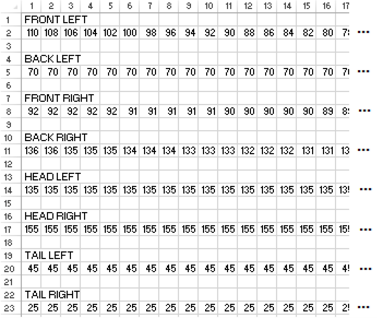
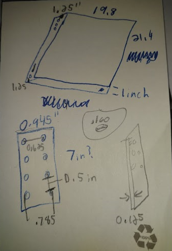
The Schmitt Trigger is able to clean up messy signals received from the IR detector and only accept input values that it will recognize as high or low values which will be defined as the threshold. This is important for our game of tag because we do not want just any voltage reading to register as being hit. Based on the voltage values being read at  various distances, we can then properly set the threshold values.  The threshold is will change by varying the resistor values and the Vcc. The following image is a picture of the calculations made by Kent (Electronics and Control engineer) for the design on the Schmitt Trigger resistor values.  

OPamp_ComparatorHysteresisDesign

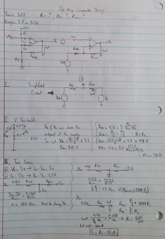
(Fig. 1 Hand written calculation for voltage threshold)

These calculations were done with the thought of the threshold voltages being 3.3V and 5V, which, according to Jeffrey (E&C division manager) is incorrect because threshold voltages should be nowhere near the supply voltages. Once Kent conducted the test on the IR emitter/detector, he found more realistic values for the threshold which are 2V and 3V. Using these two values, he re-did the calculation and got the resistor values to be R2 = 10k and R5 = Rhys = 20k. We then multiplied the values by 10 to make sure there would not be much current going through the circuit. Here is a result of the final circuit done in EagleCAD:SchmittTrigger_Schematic

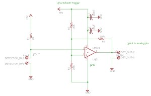
(Fig. 2: PCB Schematic of Schmitt trigger)

BJT Inverter (IR emitter driver)

The next part of the PCB that needed to be designed was the BJT inverter for driving the current for the IR emitter. The following is a picture of the calculations made by Kent for our design:

BJT_inverterDesign

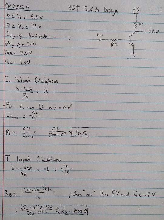
(Fig. 3: Hand written calculations for BJT inverter)

After doing the calculations, he asked Jeff to check his work for mistakes, to which Jeff said that the IcMax was not the correct value taken from the data-sheet. It should be the typical forward current of the IR LED instead of the BJT. After looking at the data-sheet for the IR LED, he found the Ic value to be 50mA instead of 500mA. In addition, the source voltage coming from the collector side should be the forward voltage of the IR LED (1.35V) and not the VCC of the 3DoT board (5V). Finally, Jeff explained that Vbe should always be around 0.7V when doing designs. After making these changes, Rb = 3.9k and Rc = 68. The following is a circuit from the resulting calculations:

Emitter_Schematic

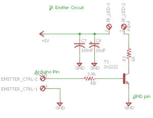
(Fig. 4: PCB Schematic of BJT Inverter)

Speaker Circuit:

Since we wish to implement a hit count system, we have decided to use a piezo speaker. It will have a resistance value that is inversely proportional to how loud the speaker will be. The following is a picture is of the circuit:

Speaker_Schematic

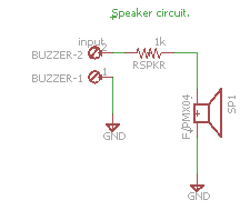
(Fig. 5: PCB Schematic of Speaker Circuit)

Motor Phase Detection/Correction (Flex Sensor Resistor)

The final part of our schematic is the motor phase detection. It includes an anti-aliasing filter and a flex sensor that acts as a potentiometer in the voltage divider. Our new mechanical design of the spider calls for the addition of a phase correction circuit. We are no longer controlling all of the legs with one motor and the head with the other, but instead we have separate motors controlling either the left or the right side. We plan for both motors to power on when a command to go forward/backward is entered, and for only one side to power on when wishing to turn left or right. After performing  the command for turning left or right, the legs may not be aligned when wishing to go forward. This is why we wish to implement a circuit that can track the phase of each motor in order to determine if they are in or out of sync. The flex sensor changes its resistance the more it is bent (See FSR test blog post), therefore with the help of Chris (3DoT David Systems) and Jeff( E&C Division manager), Kent was able to create a voltage divider with these flex sensors. We can then measure the voltage from the voltage divider of both sides and if they are not close enough, we will say they are out of phase. The OP amp that we are using is the LM324 series which is a quad OP amp package. We only had use for 3 of them so the last OP amp is connected such that it will not be using any power. The following image is of the voltage buffer circuit:

FSR_Schematic

(Fig. 6: PCB Schematic of FSR correction)

Conclusion:

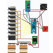
Since we have incorporated the Schmitt trigger, BJT inverter, speaker, and motor phase correction in the final PCB schematic, we will be able to meet the different system requirements with which we were given. The following page shows an image of a fritzing diagram of the entire electrical system with which we are working and includes:

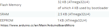
  • Sparkfun Pro Micro (32u4 microcontroller on 3DoT Board)
  • Sparkfun TB6612FNG motor driver( IC will be on the 3DoT Board)
  • Schmitt Trigger
  • IR emitter/detector
  • Voltage buffer with FSR for phase correction

FullSetupView

(Fig. 7: Full View of Electrical System)


Spring 2016 Velociraptor: Updated Walking Code #2 (Flash Memory)

By: Ashlee Chang (E&C)

Table of Contents

Fulfilling Requirements

Level 1 requirements #4 is stated as follows:

The Velociraptor shall be able to statically walk on all surfaces of the course.

Level 2 requirements #10 is stated as follows:

An ultrasonic sensor shall be implemented to the build of the robot to detect obstacles at a range of 20 cm.

The Arduino software, which uses much of C++ programming language, will be used to construct and upload the code onto the Arduino microcontroller. The MB1030 ultrasonic sensor was implemented in this updated code.

SRAM Limitations

a

Arduino memory sizes

Looking at the Arduino micro specifications as listed on their website, it’s noted the SRAM (static random-access memory) memory is a mere 2.5 kB compared to flash memory at 28 kB (taking into account the bootloader space). The previous walking code could potentially “blow up” the microprocessor using while condition loops and many variables. To avoid this problem, moving the servo angles to flash memory is not only vital, but proved to be more convenient.

The How-To

The first step is to transfer all servo angles over to an excel spreadsheet. It is important that in each column, all of these angles should be designed to be read at the same time. For example, in column 1, we see that front left = 110, black left = 70, front right = 92, etc. That means that at this point of time of 0 seconds, all servos will read at these respective angles. These indexes are related to the time the velociraptor is operating at. The velociraptor has 160 cells for each servo. The whole point of using excel is to better organize the angles and ensure that every servo has the same number of total indexes. For the second prototype, the new legs had different dimensions, thus some adjustments were required for the servo angles.

aaaa

Servos and their servo angles

Next, save this excel file as .CSV. Re-open this file, but this time using notepad.

xxxxxxx

.CSV file opened in notepad

Now it is easy to grab these angles separated by commas and insert them into an array to be stored in flash memory. Next, on the right-hand side of the Arduino software, there is a down arrow button. Click this to expand some options, and click New Tab. Name this file according to the particular servo, and end the file name with “.h” to ensure it will in fact be an h-file. For example, one .h file the velociraptor used was flashFL.h (FL for front left servo).

asdf

Next, add “const unsigned int _[] PROGMEM = {_};” in this new .h file tab. The first _ will be the name of your .h file. The second _ will be the array copied and pasted from the .CSV file opened with notepad for the associated servo angle array. The command PROGMEM stores data in flash memory as opposed to SRAM memory.

123

Using PROGMEM in the .h file

All of these .h files should be in the same folder as the main code. Double check this, else the main code will not know where to look for these files. The .CSV file is not necessary to keep in the main folder, but is easy to refer back to in case any changes are to be made.

asdfd

.h files in the main code folder

To allow the main code to utilize these arrays stored in flash, “#include_” must be stated in the beginning of the main code.

1343223

#include for the .h files

Last but not least, the array values are called from flash memory based on its index value. Use the function pgm_read_word(&_[i]); to access this data.

12321321

Reading from flash memory using indexes

Updated Walking Code

Below is the updated walking code.

WalkFLASH_ultrasonic

Note how much cleaner and shorter the code is compared to using dozens of while loops to control the eight servos of the velociraptor.

dddd

Updated walking code using flash memory

The main loop reads from all of the servo .h file arrays at one index at a time, then written to all eight servos at the same time. There are a total of 160 indexes per file, so after 160 iterations, the velociraptor will have taken two steps (one with each leg). Moving to flash memory not only saves SRAM memory, but also makes editing any servo angle at any point of time a piece of cake. A delay of 20 ms was chosen, but this could be adjusted to make the velociraptor walk slower or faster.

Also updated for the CDR presentation was implementation of the ultrasonic sensor. Every 40 cells read from the servos, there would be an object detection check. If there is an object within 10 inches of the ultrasonic sensor, the velociraptor would stop.

Also new to the code is the newly added head and tail. In order for the velociraptor to take a step, the center of mass must be moved from the center body to directly on top of the leg that will still be on the floor. Below is a table explaining the 160 cells of each array. For the first 40 cells, the left leg will take a step. This means the head and tail are already turned to the right so that all of the velociraptor weight is on the right leg that is on the floor. For the next 40 cells, both legs are on the floor as the servos both reinitialize in reparation for the next step while propelling the body forward. Because both legs are on the floor, the head and tail can now move from right to left. Etc.

rtrgr

Implementing the head and tail

Spring 2016 Velociraptor: Circuit Schematic & Servo Load Test

By: Ashlee Chang (E&C)

Table of Contents

A Clean Electronic Setup

breadboard

Breadboard testing

The electronics journey goes as so: Fritzing diagram, breadboard testing, circuit schematic, and then PCB (printed circuit board) fabrication. All electronic components are Arduino microcontroller, four batteries, eight servos, Bluetooth, ultrasonic sensor, and accelerometer. Notably, there are quite a bit of components, meaning a lot of wires needed to interface between them all. That is why the team decided that most of the wiring would be implemented on the PCB to avoid a messy project. Also, the microcontroller will be mounted directly on the PCB for this very purpose.

Servo Load Test

Servos in general draw quite a sum of current, and that current draw is proportional to the load (weight) the arm has to push against. A voltage regulator will be needed for the velociraptor, so it’s essential to see approximately how much current is drawn by these powerful servos so an appropriate regulator can be chosen. A test was conducted to see the servo load versus current draw.

xx

Servo load and current test

A bucket containing miscellaneous materials to reach a particular weight was used and weighed on a scale. Afterwards, a string was used on the bucket and attached to the servo. A simple sweep code was installed on the servo to work against this load. An ammeter was inserted into the servo and power source loop.

xxx

Servo load and current results

The results were documented in the above table. The velociraptor currently weighs 544g (not taking into account the PCB, microcontroller, sensors, and Bluetooth). Thus, the project will weigh around a total 570g-600g. Taking the current draw of 0.3A at 506g from the table, this brings the current draw of eight servos at 2.4A. If the project is estimated to be 600g, the total current draw should be close to 3A, not taking into account current going to other parts of the circuit. Thus, the voltage regulator must be capable of handling over 3A.

Voltage Regulator

The voltage regulator is the only major component on the circuit schematic. Choosing a proper one was difficult. A decision between an LDO (low dropout voltage) voltage regulator versus switching regulator was contemplated. The switching regulator is actually highly efficient compared to the LDO voltage regulator. The lesser the inefficiencies, the lower amount of energy will be wasted as heat. Because the velociraptor shall be designed as a child’s toy, hot electrical pieces is a definite no-no that must be avoided for the health and safety of the user. With all switching regulators, there needs an inductor in the suggested schematic, which requires specific placement of the schematic in terms of distance on the PCB. Finding a switching regulator with an internal inductor proved to be impossible. In addition, there are not many switching regulators capable of stepping down small voltages. In the velociraptor’s case, the voltage had to be stepped down from 7.4V to 6.0V, which is only a change of 1.4V. Due to the complexity of switching regulators, the team decided on an LDO voltage regulator.

Some spec considerations that must be taken into account were: 5A maximum current output, input of 7.4V, output of 6V, capable of stepping down 1.4V, efficient, and through-hole (the smaller the package size, the hotter the component can get). The voltage regulator agreed on was MIC29512. Some additional features include current limiting protection, thermal shutdown, and an enable input pin that can be used to turn off the voltage regulator when not in use.

x

MIC29512 Voltage Regulator

Heat Sink

If the voltage regulator were to be a surface mounted piece, some copper embedding must be implemented. However, seeing the voltage regulator is a through-hole TO-220 package, a screw on heat sink can be used. For calculations based on the datasheet, the math is as follows: Rtsa = [125 – 50] C / 3W – 2 C/W – 1 C/W = 22 C/W. Any heat sink under 20 C/W would be ideal, but one with a specification of 9.6 C/W was chosen because, after all, this is a child’s toy.

xxxx

Heat sink choice

Eagle Circuit Schematic

schematicfinal

Velociraptor circuit schematic

The final circuit schematic is shown above. Both two batteries will be in series, and those two are in parallel. The resistors in between are used to help with any possible offset in between the two battery pairs. Transistors were placed to use the enable pin. A large capacitor needs to be next to the batteries. A TO-220 package was made for the schematic, and the recommended schematic was constructed based on the MIC29512 datasheet. The respective resistors used were calculated to output 6V on the voltage regulator. The batteries were connected to both the microcontroller (which can take inputs up to 12V) and the voltage regulator. The regulator feeds the servos as to get to that optimal voltage of 6V. The Arduino micro is placed directly in the schematic. Lastly, some simple connectors were used for the sensors, actuators, and Bluetooth.

Spring 2016: 3DoT David Arxterra Firmware Configuration

By: Chris Hirunthanakorn (Systems, Mission, and Test)


Table of Contents

Arxterra Firmware Configuration for 3DoT David

Introduction:

Because the 3DoT David is going to be controlled by the Arxterra App, the robot must use the Arxrobot Firmware that is available from here (https://github.com/arxterra/arxrobot-firmware/releases). For our particular robot, there were several things that needed to be changed or added such as the code for the tagging system, the subroutines for controlling the motors, and any custom commands that need to be added. This blog post covers all of the work done for the configuration of the Arxrobot Firmware for the 3DoT David as it went through various design changes and revisions.

Related Requirement:

All of the information presented in this blog post is related to the following project level requirement.

  • The 3DoT David shall be controlled by the Arxterra App used on a smartphone.

First Modification of Arxrobot Firmware for PDR Demonstration

Because the 3DoT board was not ready for use by the PDR Demonstration, the base of a store bought hexbug was used with an Arduino Uno and an Adafruit Motor Shield in order to demonstrate the control of the robot with the Arxterra App. The first modification to the Arxrobot Firmware included changes to the pin and command definitions in the pinouts_robot.h file, including the header files needed for the Adafruit Motor Shield, and the creation of functions needed to control the motors and the movement of the robot.

Changes to the pinouts_robot.h file

There was only one change to the pinouts_robot.h file, which was the addition of one custom command definition. This is the LASER_CONTROL command that is meant to demonstrate the control of our tagging system.pinouts change 1

Changes to the command handler function

The first change to the command handler function involves changing which function is called when the move command is sent from the Arxterra App. Instead of calling the move_TB6612FNG() function, it now calls our detectDir() function.

The second change is to add the new custom command for LASER_CONTROL. A new elif block is added to execute the correct function when the custom command is sent.command change 2
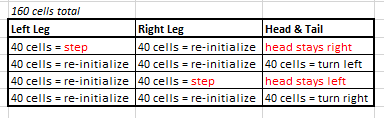
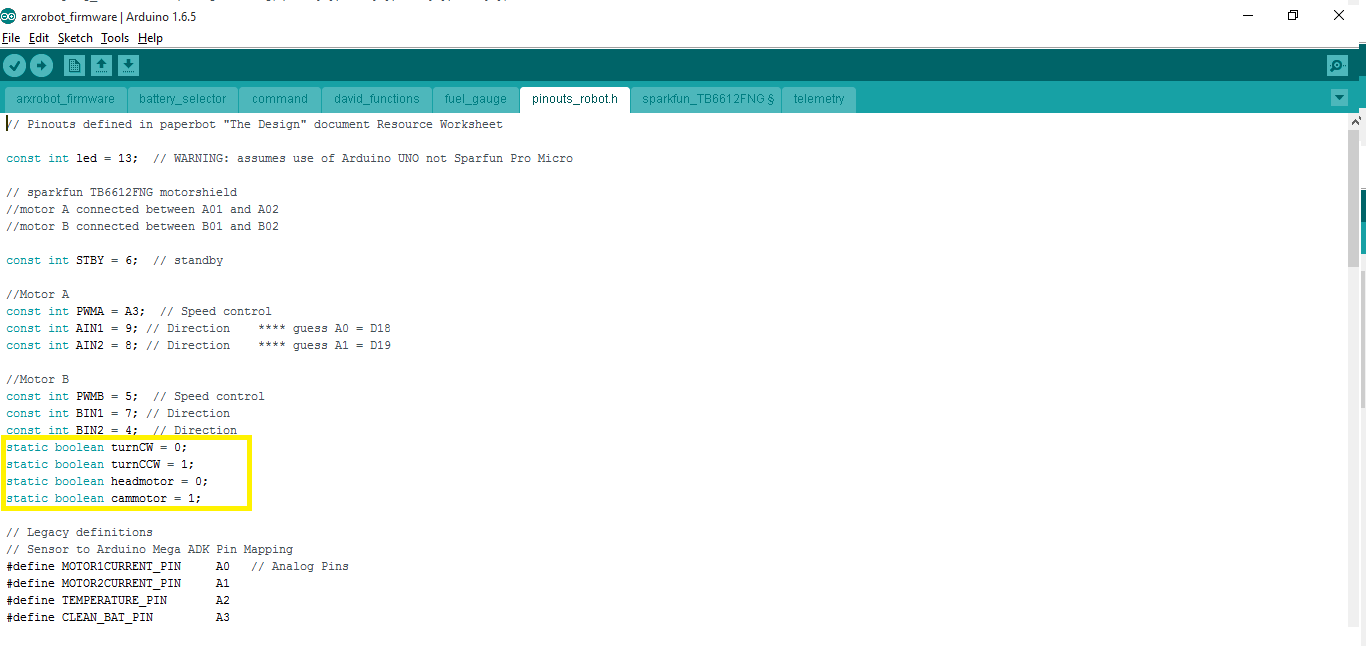
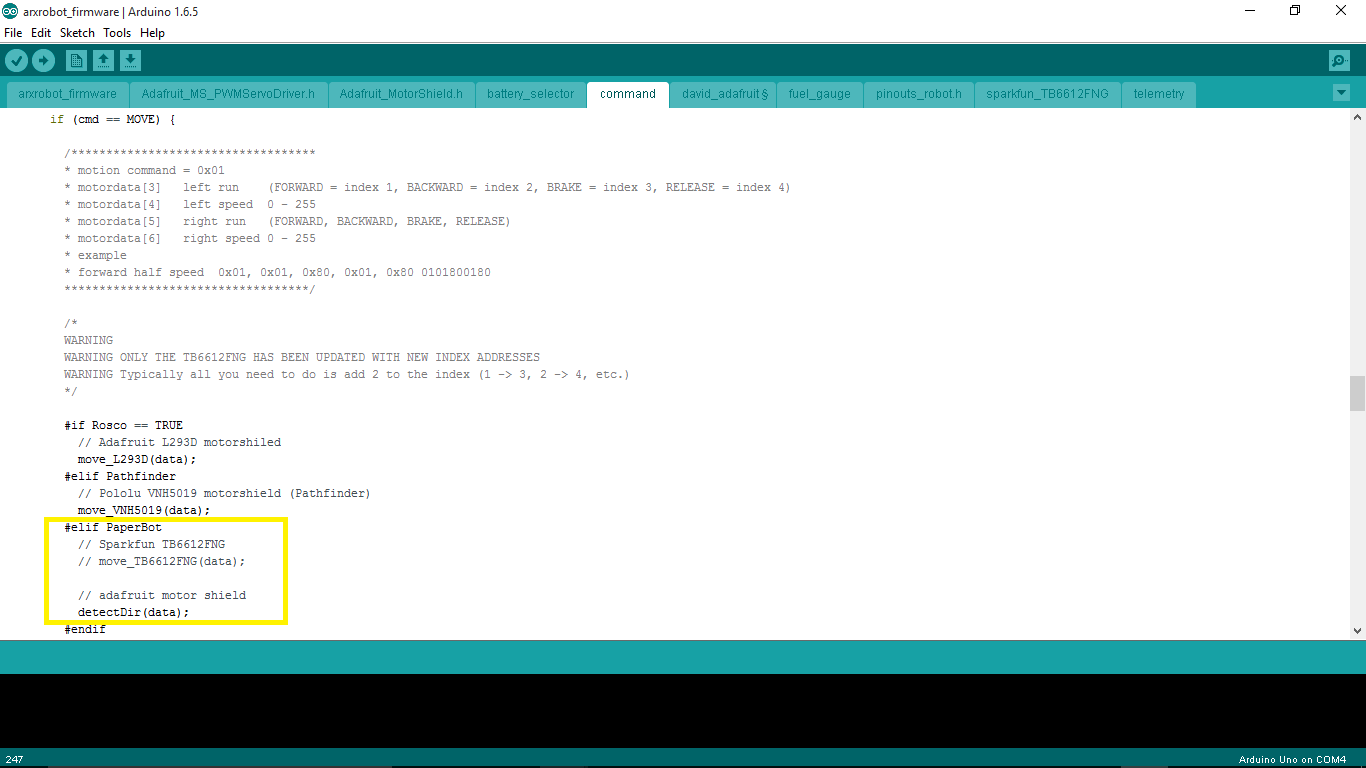
Functions to control motors and movement of the robot

Our Electronics and Control Engineer helped me create these functions by showing how to control the motors using the Adafruit Motor Shield. The detectDir() function interprets the move command sent from the Arxterra App to determine the direction the user wants the robot to move. From there, it will call the corresponding function that will move the motors. For example, if the direction is forward, the move_camf() function will be called and that function will cause the camMotor to start. The laser_status() function is for demonstrating the use of a custom command to control our laser/tagging system by turning an LED on or off.


void adafruitinit(){

 pinMode(10, OUTPUT); // Sets pin A10 as an output

}

void detectDir(uint8_t * motordata){

 // Create the motor shield object with the default I2C address

 Adafruit_MotorShield AFMS = Adafruit_MotorShield();

 Adafruit_DCMotor *headMotor = AFMS.getMotor(1);

 Adafruit_DCMotor *camMotor = AFMS.getMotor(2);

 AFMS.begin();  // create with the default frequency 1.6KHz

 uint8_t headdir = motordata[3];

 uint8_t camdir = motordata[5];

 if (headdir == 1 && camdir == 1){ // forward

  move_camf(camMotor, motordata[6]);

 }

 if (headdir == 1 && camdir == 2){ // right

move_headr(headMotor, motordata[4]);

 }

 if (headdir == 2 && camdir == 1){ // left

move_headl(headMotor, motordata[4]);

 }

 if (headdir== 2 && camdir == 2){   // backwards

move_camb(camMotor, motordata[6]);

 }

 if (headdir == 3 && camdir == 3){ // Brake

motor_brake();

 }

 if (headdir == 4 && camdir == 4){ // Release

headMotor -> run(RELEASE);

camMotor -> run(RELEASE);

 }

}

void motor_brake(){

}

void move_camf(Adafruit_DCMotor *camMotor, byte pwm){

 camMotor -> setSpeed(pwm);

 camMotor -> run(FORWARD);

}

void move_camb(Adafruit_DCMotor *camMotor, byte pwm){

 camMotor -> setSpeed(pwm);

 camMotor -> run(BACKWARD);

}

void move_headr(Adafruit_DCMotor *headMotor, byte pwm){

 headMotor -> setSpeed(pwm);

 headMotor -> run(FORWARD);

}

void move_headl(Adafruit_DCMotor *headMotor, byte pwm){

 headMotor -> setSpeed(pwm);

 headMotor -> run(BACKWARD);

}

void laserStatus(byte stat){

 if (stat == 1){

digitalWrite(10, HIGH);

 }

 if (stat == 0){

digitalWrite(10, LOW);

 }

}

Second Modification of Arxrobot Firmware

After the PDR Demonstrations, we were able to obtain the Sparkfun TB6612FNG Dual Motor Driver that is used on the 3DoT board and made the modifications to the Arxrobot Firmware to use this hardware instead. The changes made include removing the header files for the Adafruit Motor Shield, changing the functions used to control the motors, and modifying the functions in the sparkfun_TB6612FNG file. There were also a few additional definitions that were added to the pinouts_robot.h file.


Additions to the pinouts_robot.h file

Definitions for which motor and which direction were added to the pinouts_robot.h file.pinouts change 2

Changes to functions to control motors

The main changes to the detectDir() function are that they use the modified functions from the sparkfun_TB6612FNG file.


void detectDir(uint8_t * motordata){

 uint8_t headdir = motordata[3];

 uint8_t camdir = motordata[5];

 if (headdir == 1 && camdir == 1){ // forward button pressed – move cams motor forward

move_TB6612FNG(cammotor, turnCW, motordata[6]);

 }

 if (headdir == 1 && camdir == 2){ // right button pressed – move head motor right

move_TB6612FNG(headmotor, turnCCW, motordata[4]);

 }

 if (headdir == 2 && camdir == 1){ // left button pressed – move head motor left

move_TB6612FNG(headmotor, turnCW, motordata[4]);

 }

 if (headdir== 2 && camdir == 2){   // backwards button pressed – move cams motor backwards

move_TB6612FNG(cammotor, turnCCW, motordata[6]);

 }

 if (headdir == 3 && camdir == 3){ // Brake

brake_TB6612FNG(headmotor);

brake_TB6612FNG(cammotor);

 }

 if (headdir == 4 && camdir == 4){ // Release

release_TB6612FNG(headmotor);

release_TB6612FNG(cammotor);

 }

}

Here is the updated code for the sparkfun_TB6612FNG file.

void setup_TB6612FNG(){

 pinMode(STBY, OUTPUT);


 pinMode(PWMA, OUTPUT);  // motor A

 pinMode(AIN1, OUTPUT);

 pinMode(AIN2, OUTPUT);


 pinMode(PWMB, OUTPUT);  // motor B

 pinMode(BIN1, OUTPUT);

 pinMode(BIN2, OUTPUT);

 brake_TB6612FNG(0);    // brake

 brake_TB6612FNG(1);  

}

void brake_TB6612FNG(boolean motorNumber)     // initialize or stop TB6612FNG

{

 /* This stops the specified motor by setting both IN pins to HIGH */

 if (motorNumber == headmotor) {

digitalWrite(AIN1, HIGH);

digitalWrite(AIN2, HIGH);

 }

 else

 {

digitalWrite(BIN1, HIGH);

digitalWrite(BIN2, HIGH);

 }

  digitalWrite(STBY, HIGH);

}

void safeRover()

{

 digitalWrite(STBY, HIGH);  // TB6612FNG disabled (high impedance)

}

void move_TB6612FNG(boolean motorNumber, boolean motorDirection, int motorSpeed)

{

 /* This Drives a specified motor, in a specific direction, at a specified speed:

– motorNumber: motor1 or motor2 —> Motor 1 or Motor 2

– motorDirection: turnCW or turnCCW —> clockwise or counter-clockwise

– motorSpeed: 0 to 255 —> 0 = stop / 255 = fast */

 boolean pinIn1;  //Relates to AIN1 or BIN1 (depending on the motor number specified)

 //Specify the Direction to turn the motor

 //Clockwise: AIN1/BIN1 = HIGH and AIN2/BIN2 = LOW

 //Counter-Clockwise: AIN1/BIN1 = LOW and AIN2/BIN2 = HIGH

 if (motorDirection == turnCW)

pinIn1 = HIGH;

 else

pinIn1 = LOW;


//Select the motor to turn, and set the direction and the speed

 if(motorNumber == headmotor)

 {

digitalWrite(AIN1, pinIn1);

digitalWrite(AIN2, !pinIn1);  //This is the opposite of the AIN1

analogWrite(PWMA, motorSpeed);

 }

 else

 {

digitalWrite(BIN1, pinIn1);

digitalWrite(BIN2, !pinIn1);  //This is the opposite of the BIN1

analogWrite(PWMB, motorSpeed);

 }

 //Finally , make sure STBY is disabled – pull it HIGH

 digitalWrite(STBY, HIGH);

}

void release_TB6612FNG(boolean motorNumber){

 if (motorNumber == headmotor) {

digitalWrite(AIN1, LOW);

digitalWrite(AIN2, LOW);

 }

 else

 {

digitalWrite(BIN1, LOW);

digitalWrite(BIN2, LOW);

 }

 digitalWrite(STBY, HIGH);

}

Final Modifications

Due to several changes with the design of the 3DoT David, there were modifications to the functions that control the motors and the tagging system. With the new movement system design, both motors will need to be controlled at the same time in order to move because each motor is driving one set of three legs. Additionally, the smoothest movement of the legs required the PWM value to be set to the maximum of 255. If it was any less, the motion of the 3DoT David would look very slow and feel weird. Because of the way the ArxRobot App is set up, the user has to press and hold the direction button to increase the speed of the motors to move in that direction. The code was changed so that the PWM value would be a constant 255 and that the leg movements would be fluid.

For the emitter part of the tagging system, it was decided that the IR emitter will be on whenever the 3DoT David is moving and is off the rest of the time. This is because the ArxRobot App can only send one command at a time and the alternative method of controlling the IR emitter would be using a slider on the app to turn it on or off. Implementing this in the code was easily done by incorporating the command into section of the commandHandler function that executed the move commands.

For the detector part of the tagging system, code was added to the main loop to check the output of the IR detector and if the 3DoT David should be disabled. The code is executed after the commandHandler function is called and checks if the robot has been tagged. If so, a counter would be incremented and if that counter reaches three, the robot will be disabled. When hit, the speaker will make a sound and the robot will not check for tags for 5 seconds. When the robot is disabled, it will not respond to any commands for 10 seconds and play a short song to indicate this change. All of this is done by using a flag variable to keep track of whether or not a tag has occurred. The flag will be cleared after 5 seconds have passed. When this has happened three times, the code will enter a loop that keeps it from responding to commands for 10 seconds.

Additionally, all of the extraneous code that was a part of the latest version of the arxterra firmware was removed. This includes all of the telemetry and sensor definitions that were left over from older projects that are not being used for the 3DoT David. All of the code used for debugging and testing were also removed or commented out to make sure additional processing time was not being used up.


Conclusion:

This blog post explains the process of the development of the Arxterra firmware code. It covers all of the changes done to prepare the demonstrations for the PDR and CDR.

Sources:

  1. https://github.com/arxterra/arxrobot-firmware/releases

Spring 2016 3D SMD: Vacuum Pump Trade-off Study V2

By Henry Nguyen ( Electronics and Control)

Table of Contents

Introduction

In order to find a vacuum pump that best suits our pick and place SMD machine, we needed to compare several different options. Considering pressure and cost will be crucial for this trade off study. Our goal is to find a vacuum pump that is able to pick up surface mount components and IC chips when connected to a 12V solenoid valve. We found that we can modify a 60 -100 gallon Tetra Whisper Aquarium pump to act as a vacuum for the price of $19.00.

—Equipment and Materials

  1. A 5mL syringe with a small needle with a diameter of less than 0.50mm

Syringe 5mL

Figure 1. 5 mL Syringe   

Needles-min

Figure 2. Needle heads

  1. Various surface mount components and IC Chips

ICs-min

Figure 3. Various surface mount components and IC Chips

  1. Vacuum pump (Modified aquarium pump)
    1. Product Dimensions: 3.4 x 5 x 8.4 inches ; 2.1 pounds

Tetra 100 Gal-min

Figure 4. Tetra Aquarium Pump

  1. 3/16” tubing

Tubing-min

Figure 5. Tubing

  1. 12V Solenoid Valve

Figure 6. 12V Solenoid Valve

Figure 6. 12V Solenoid Valve

—Procedure

  1. We shall modify the following aquarium pump in order to turn it into a vacuum pump. The following link provides step-by-step details on how to modify our aquarium pump
    1. http://www.instructables.com/id/Circuit-Board-Lab-POV-Business-Card/step5/
  2. Tubing length shall be cut to be as short as possible to allow maximum suction pressure. The size shall be determined based on the design of our aluminum surface table. (Approximately 1.5 – 3 ft)
  3. A 5mL syringe shall be used as our vacuum head and will be modified by connecting our vacuum to the 12V solenoid valve and then to our syringe.
  4. After setting up our equipment, we shall be testing whether or not our vacuum is able to pick up a 402 component.
  5. Next we will be testing a heavy component in order to determine if our small needle is able to pick up the IC Chip.
  6. Our last step is to test how much mass our vacuum pump is able to pick up. In order to do so, we will have a small scale with an accuracy of 0.1 grams and we will place an object on that scale. We will use our vacuum to see how much grams is deducted of the total mass when attempting to pick up the object. The following video shows a demonstration of this process.
    1. http://www.exair.com/pages/theater.aspx?gi=13001&dlg=1&gf=Vacuum+Generators


—Results

The following link is a rapid prototyping of our aquarium pump.

https://www.youtube.com/watch?v=a32c-TGHdyE&feature=youtu.be

Vacuum Strength Test

Figure 7. Strength of Vacuum

For our strength tests of our vacuum, I decided to use an Vero Pica Gomas candy due to ease of access. The mass of this candy is 4.53 grams. I figured that if our vacuum has the strength to pick up this candy, other strength test will not be necessary since the mass any surface mount components we will be required to use will not exceed 4.53 grams. I found that our aquarium vacuum pump was able to successfully lift this candy into the air.

Weight of 37 603 components

Figure 8. 37 0603 components on a scale

Next I decided to weigh 37 0603 components on a scale with a tolerance of 0.01 grams. I found that 37 0603 components did not reach a mass of 0.01 grams. We can safely assume our vacuum will be strong enough to pick up these components.

Picking up 603 component

Figure 9. Vacuum nozzle picking up 0603 component

I found that our vacuum nozzle and vacuum was able to successfully pick up a 0603 component without falling off. The image above shows a 0603 component on the tip of our vacuum nozzle with our vacuum currently running.

To conclude our findings, I found that our aquarium pump was able to be successfully turned into a vacuum pump. A syringe was modified in order for it to be used as a vacuum nozzle; however, we did eventually purchased a vacuum nozzle meant to pick up 0402 components.  We currently only had access to 0603 components therefore we ran our tests with 0603 instead of 0402 components. We found that we were able to successfully pick up our 0603 components. When our solenoid valve was on, our vacuum head became operable and we were able to pick up 0603 components. Once we shut off our solenoid valve, the 0603 components would either fall off our syringe, or stick on to our nozzle. This would not be an issue because the PCB on our machine will have solder paste on it allowing the components to easily be placed onto the PCB.

—Conclusions

The final decision for our vacuum pump is to use the Tetra Whisper 60 – 100 gallon aquarium pump. The cost of this modified vacuum pump is $19 which is extremely cost efficient. We have also found that this pump is very quiet and will not cause much noise when running side-by-side with our X-Y plotter. Our vacuum pump and nozzle is able to pick up a 0603 component which is crucial to the design of our 3D SMD pick and place machine.

—References

Vacuum Pump modification and image:

Sponges, S. (n.d.). Build an SMD Vacuum Pick and Place Tool. Retrieved February 25, 2016, from http://www.instructables.com/id/Circuit-Board-Lab-POV-Business-Card/step5/

Vacuum Pump mass test:

EXAIR: Manufacturing compressed air products since 1983. (n.d.). Retrieved February 25, 2016, from http://www.exair.com/pages/theater.aspx?gi=13001

ICs Image:

Curious Inventor. (n.d.) Hand full of SMDs Labeled. Retrieved February 25, 2016, from

http://store.curiousinventor.com/media/smt/hand_full_of_smds_labeled.jpg

Tetra Whisper Aquarium Pump Image:

Tetra Whisper Air Pump (Non-UL). (n.d.). Retrieved February 26, 2016, from http://www.amazon.com/Tetra-77851-Whisper-Pump-10-Gallon/dp/B0009YJ4N6/ref=sr_1_1?s=pet-supplies

3/16” Tubing Image:

Python. (n.d.). Retrieved February 26, 2016, from http://www.amazon.com/Python-Airline-Tubing-Aquarium-25-Feet/dp/B000255NYQ/ref=pd_bia_nav_t_1?ie=UTF8


Spring 2016 3D SMD: Me Uno Shield and Software

By Henry Nguyen (Electronics and Control)

Table of Contents

Introduction

Originally when purchasing our X-Y plotter from MakeBlock, we were given a Me Orion microcontroller. This microcontroller was enough to power two stepper motors for our X and Y movement; however, because we are modifying our X-Y plotter to become a 3D SMD pick and place machine, we are required more stepper motors for our Z-axis and A-axis (rotation). Our solution was to purchase a Me Uno Shield ($10.00) from MakeBlock which has the capability to control four 12v stepper motors.

Me Orion

Figure 1. Me Orion Front

Figure 1. Me Orion Front

Figure 2. Me Orion Back

Figure 2. Me Orion Back

Our Me Orion microcontroller shown above has 8 RJ25 ports. These ports are all mapped to SCL, SDA, power, ground, and 2 pins on an Atmega 328-AU microprocessor. The two red ports 1 and 2 both supply 12v with two PWM pins for stepper motor control. Pins 3,4,5,6,7,8 all supply 5 volts. Due our stepper motors requiring 12 volts, using this microcontroller will limit us to only 2 stepper motors. After proper research, we found that purchasing a Me Uno Shield from MakeBlock and attaching it to an Arduino Uno, we will have the ability to control 4 stepper motors.

Me Uno Shield

Figure 3. Me Uno Shield and Arduino Uno

Figure 3. Me Uno Shield and Arduino Uno       

Figure 4. Me Uno Shield Back

Figure 4. Me Uno Shield Back

As shown above, the Me Uno Shield has 10 total RJ25 ports. Each port has SCL, SDA, power, ground, and 1-2 pins mapped to an arduino uno. The 4 red ports: 1, 2, 9, and 10 are supplied with 12v. Port 1 has PWM Pins (10 and 11) while port 2, 9, and 10 only have 1 PWM pin and a digital pin. We were worried that 2 PWM were needed to control stepper motors; however, after running some tests, and properly mapping out our pins on our software, we found that we were able to control a stepper motor on all red RJ25 ports.

Figure 5. Me Uno Shield 10 Port Pinouts

Figure 5. Me Uno Shield 10 Port Pinouts

The image above is the Me Uno Shield 10 port pinouts. All this information is also shown on back of our Me Uno Shield. (Image provided for easier referencing).

Software

Figure 6. Me Uno Shield Pin Mapping

Figure 6. Me Uno Shield Pin Mapping

The Me Orion and Me Uno Shield did not have the same pin outs; therefore, on our Gcodeparser code, we were required to correctly map out our new pins for each stepper motor we will be using. We found that although we mapped our stepper motors properly on our arduino code, our GRemote (java) did not read our pin outs properly. In order to fix this, we had to evaluate the java code provided by the Gremote in order to understand why our stepper motors will not take any Gcode commands even though our pin outs on our arduino code was correct.

From our GCodeParser_Makeblock Orion folder, we had to navigate to two different files:

GRemoteFull → Source → GRemote.java

Figure 7. GRemote.java Line 1584 - 1598

Figure 7. GRemote.java Line 1584 – 1598

In this GRemote.java file, we found that our stepper motors direction, steps, minimum, and maximum limiting switches for each stepper motor X-Y and servo Z  pins were being taking from the “GRemote.app/contents/settings.ini.” We then decided to navigate to this location.

GRemoteFull → Java → bin → GRemote.app → Contents → Setting.ini

Figure 8. Settings from Me Orion

Figure 8. Settings from Me Orion

As we suspected, we found that the settings were defaulted to the pins from our Me Orion. 11, 10, 17, and 16 is our direction, step, minimum and maximum limiting switches for our X-Axis stepper motor.  3, 9, 13, and 12 is our direction, step, minimum and maximum limiting switches for our Y-Axis stepper motor. 15 is our direction for our Z servo. 174.9781 is our steps_per_mm for X, Y, and Z. After adjusting these pinouts to our Me Uno Shield, we obtain the following settings:

Figure 9. Settings from Me Uno Shield.

Figure 9. Settings from Me Uno Shield.

I was able to adjust our GcodeParser arduino code to allow our Z-axis to be treated as a stepper motors instead of a servo. After many attempts, and mapping my Z-Axis to Port 10 (Digital pin 6 and 7), I was able to control our Z-axis on Port 10. I had to map it properly on the GcodeParser arduino code, and adjust our GRemote settings file as shown in figure 8. In line 10 and 11, the Z-Axis stepper motor is mapped to Port 6 (direction) and Port 7 (step). Although only pin 6 is a PWM pin, as long as we mapped our direction of our stepper motors to the PWM pins, we were able to control our stepper motors without any problems. I then attempted to map our Z-Axis stepper motor to port 1, 2, and 9 on our Me Uno Shield. As long as I properly mapped the pins, I found that I was able to control the stepper motor using our GRemote in any 12V RJ25 ports.

Figure 10. GRemote

Figure 10. GRemote

Now when we open our GRemote, we can see in Figure 10 on the left, each case ($) shows the correct pinouts according to our java and setting.ini file. For case $1, X10, Y12, and Z7 all represents our step pin. For case $2, X11, Y9, and Z6 represents our direction pin. For case $3, X17 and Y8 are our minimum limiting switch pins while Z is left empty because we have yet to implement a limiting switch pin for our Z-Axis stepper motor. For cae $4, X16 and Y13 are our maximum limiting switch pins while Z is left empty for the same reason stated prior. These cases can be found in our arduino process_string module. An example of case $1 is shown below.

Figure 11. Process_string Case $1 Example

Figure 11. Process_string Case $1 Example

Conclusion

Overall, being able to control more than two stepper motors was a breakthrough for us in this project. We are now able to have full control over more than two stepper motors which is crucial for our 3D SMD pick and place machine. We are now able to control X, Y and Z axis. In order to control our A axis, I will need to focus more on software to see how we can add another stepper motor to our GcodeParser. Now that are machine is able to communicate with our GRemote and accept GCode commands properly, we are one step closer to success of this project.

Reference

Me UNO Shield. (n.d.). Retrieved April 04, 2016, from http://learn.makeblock.com/me-uno-shield/


Spring 2016 3D SMD: Aluminum Surface Table

By Henry Nguyen (Electronics and Control)

Table of Contents

Introduction

For our 3D SMD pick and place machine, it is extremely vital that we have an aluminum surface table in order to put our PCB, reel feeders, and IC tray. This surface table is to be the exact size of our makeblock X-Y plotter with the dimensions of 21.40” x 19.80” (inches). When designing this aluminum surface table, it is important to get all the dimensions correct and to have about 2 inches of each side in order to have a 1.0 inch bend on each side. This will allow us to attached our aluminum surface legs.

Design

Figure 0 Rough Sketch

Figure 0. Rough Sketch of Aluminum Surface TAble

Before manufacturing, it is vital that we design the aluminum surface table. After taking proper measurements, I was able to design the aluminum surface table on solidworks.

Figure 1. Aluminum Surface

Figure 1. Aluminum Surface

The image above is the aluminum surface with the dimensions of 21.40 x 19.80 x 1.00 inches. There is a slit and two holes on the surface for our reel feeders. Our reel feeder will screw into the holes and the slit is for our cut tape to go through the hole and under the surface table when operating. This is to prevent clutter. There are also 6 holes on the surface table with the dimensions of 21.40 x 1.00 inches. These holes are in the exact location as our XY plotter legs. This is for our legs to connect to our X-Y plotter and the aluminum surface.

Figure 2 Aluminum Surface Leg (Solidworks)

Figure 2: Aluminum Surface Leg (Solidworks)   

Figure 3. Aluminum Surface Leg Dimensions

Figure 3. Aluminum Surface Leg Dimensions

The two images above is the Solidworks design of our aluminum surface legs and dimensions. Our leg will be 0.95 x 7.00 Inches long with 16 holes. These holes will allow us to attach our legs to both our aluminum surface table and X-Y plotter. The dimensions were accurately measured in order for our manufacturer to create an exact fitment. Each hole is 0.160 inches in diameter and is 0.66 inches apart center to center. The thickness of our legs will be 1/8 inch thick (0.125 inches).  

Production

Figure 4. Aluminum Surface Table Assembled

Figure 4. Aluminum Surface Table Assembled

The image above is how our aluminum surface table will look like. The clamping system, reel feeder holes, and slit will be done later when we finalized the exact placement. The clamping system cannot be implemented until we are able to assemble our X-Y-Z-A Axis for our machine which is when we will be able to define our origin. Once finding our origin, we will be able to implement our clamping system and reel feeder placement.

Figure 5. Aluminum Surface Table Manufactured

Figure 5. Aluminum Surface Table Manufactured

Figure 6. Aluminum Leg Manufactured

Figure 6. Aluminum Leg Manufactured

We were able to get our part manufactured with exact sizes as our Solidworks model. The reel feeder placement and clamping system will be defined later. As shown in Figure 6, we were able to attach aluminum surface table and X-Y plotter by our aluminum leg. With the design of multiple holes, we are able to move our aluminum surface table up and down by a multiple of 0.5 inches at a time.

Conclusion

Overall, I believe the design of this aluminum surface table turned out perfectly. The thickness of 1/8 T6 aluminum surface is able to support a PCB and many reel feeders that may be implemented in future semesters. When attaching our aluminum surface to our X-Y plotter, every screw was able to fit with ease. We used two washers and a hex nut for safety when connecting each of our legs to our X-Y plotter and surface table.

Spring 2016 3DOT Goliath,Assembling and Testing the 3Dot Board

By:  Ayman Aljohani (Project Manager)

For our Goliath project we will be using a custom made PCB that contains a microcontroller (known as the 3Dot Board) that will perform various tasks (ex. movement, laser shot, detector).  The physical PCB will be provided for us; however, it is required to solder all the components onto the PCB.

The steps we will be taking to solder the parts onto the PCB:

  1. Apply flux to the area you will be soldering and apply the soldering iron.
  2. Place the component on top of the soldering iron and heat the area to create contact between the soldered iron and the component.Soldering 3DOT Board components manually with Soldering Iron
  3. Check with multi-meter to make sure the components are connected to the PCB
  4. If alignment needs to fixed, we will use the heat gun to simultaneously heat the area to remove the component.
  5. Hold heat gun 3~4 inches away from the PCB for 30 seconds to heat up the board (prevent heat sync).                                                          heat gun
  6. Now aim the heat gun around 2 inches at the area you’re interested in for 15 seconds.Soldering with heat gun
  7. Apply little pressure to fix the alignment of the component.


Applying solder base to the area, this could be done in two ways:

a-All at once using stencil

Applying solder base using stencil

then clean the extra solder base manually

aplpling solder base


b-Manually apply solder base to all parts. This option takes loner time, but it will give a clear idea about 3DOT components and connections which makes the troubleshooting easier.


rsz_manually_solder_base


2- Use tweezers to place the components on the 3DOT Board:

rsz_tweezer  rsz_tweezer_2


3- After placing the component correctly, apply heat by placing the PCB in an oven


Assembled 3DOT Board:

rsz_final_product


The steps we will be taking to remove parts on the PCB:

  1. Apply flux to the area interested in to remove the soldering iron from a component.
  2. Put de-soldering on the area you want to absorb the soldering iron and apply the heated solder tip on top of it.
  3. Apply until you see the solder iron gets absorbed by the de-soldering material.
  4. Remove the component after most of the soldering iron has been removed.


Spring 2016 3DOT Goliath, Progression of Laser Tag components


By: Kevin Moran (Electronics and Control Engineer)


In this post we will explore the progression in the components explored throughout this project to make the Laser Tag game possible.


  • My first idea was to use a laser diode as the emitter and a Photo-resistor as the receiver.
    1. Pros:
      1. 15 meter range
      2. No Assembly required
  • Power dissipation of 75mW
  1. Cons:
    1. Dangerous to the human eye
    2. No circuit to build and learn from


Simplistic Laser Receiver build with Fritzing diagrams (Photo-resistor)

fritzing  danger


  • Since we are designing a 3DoT Rover that will be manufactured for children, the laser was discarded. My next idea was to use a simple LED alongside a collimator to simulate a safer laser beam.
    1. Pros:
      1. Safe to use
      2. 3 feet range
  • Power dissipation of 60mW
  1. Cons:
    1. Beam had a 3 inch diameter from 3 feet distance
    2. Did not meet the “cool” requirement

collimator


Red LED with collimator powered by a 4.5V power supply and       220ohm resistor


red with col

  • The third option to be able to satisfy our requirements for the laser tag game was to use a Photo-transistor as a receiver alongside an IR LED as the emitter
    1. Pros:
      1. Safe to use
      2. Will require PCB board to cancel our noise and filter signal
  • Analog voltage output can be manipulated
  1. Cons:
    1. Output contains noise.
    2. Range has to be worked on
  • Not visible to naked eye


Although the range is not as impressive as the laser, this is a safe device to use, as Infrared Light is not absorbed by the human eye. By using this device I will be able to satisfy the rubric for the PCB schematic design, as I will be adding on a Schmitt Trigger, which will be discussed in the following blog post.


Emmiter/ Receiver

emitter


Voltage output using Arduino Analog Pins


output


This circuit still needs to be filtered out and passed through an Inverting Schmitt Trigger. The Schmitt trigger will filtered out the noise and using voltage resistors there will be two voltage thresholds. Which will then be digitized and sent to the microcontroller for processing.

Spring 2016 3DOT Goliath,Troubleshooting the 3Dot Board


By:  Tae Min Lee (Systems)

After finishing the assembly of the 3Dot Board with our mentor Nick and Lawrence at AOSA we had to troubleshoot if we had any bad connections.  These are some of the procedures Nick and the group came up with to test the 3Dot Boards by following the procedures shown below:

Test Procedure:

  1. Take out the battery before testing using a multi meter
  2. Set the multi meter to measure resistance setting in the 100k ohm range
    1. Check for shorts on the Dual Motor Driver Chip
    2. The measured impedance of any two pins should be much higher than the 100k ohm.
    3. If a value of 0 resistance or close is displayed than you have a short
  3. Check H-Bridges are bridged based on the schematic (figure 1)
    1. Checked A01, A02, B02, B01
  4. Upload a simple code to test the motors (figure 2)
    1. Measured the voltage across the motor terminals to make sure the correct voltage was outputted

circuit 1


code


Conclusion:

No shorts were found on the 3Dot Board and the H-Bridge connections were connected.  However, we encountered a problem when we tested the motor code only Motor A was operating at the time.  Motor B on the other hand was not operating and the measured voltage across the motor B terminal was zero.  We had Nick perform additional test on the 3Dot board and from his analysis the possible problems were either the Dual Motor Driver or the Atmel Chip being damaged during assembly or other causes (ex. shipment, electro static, heat, etc.).

3DOT


References: 

1- https://www.pololu.com/product/713

2-http://forum.arduino.cc/index.php?topic=214730.0