Spring 2016 3DOT Goliath, Uploading the Firmware onto the 3Dot Board

By:  Tae Min Lee (Systems)

Before we upload any programs onto the PCB we have to upload a firmware.  The ATMEL Mega32u4 we soldered on the 3Dot cannot function because the chip has not been programmed.  In order to make the PCB programmable we will require to upload a firmware (programmable program) using ISP (In-System Programmer).

Steps we will be taking to uploading the firmware onto the PCB:

  1. Install the USB driver for the AVRISP mkii (Guide: USB Driver Installation).
  2. ISP connection pins are needed to communicate with a device through the SPI (Serial Peripheral Interface) using pins MOSI, MISO, Vcc, GND, SCK, RESET.
  3. Using the ISP connector connect it to the ICSP header to reprogram the microprocessor.
    1. When connecting the ISP connector onto the ICSP header make sure the orientation of the connection is correct. For more info refer to the AVRISP mkii Programming document.
  4. Download the following zip file from https://github.com/sparkfun/Arduino_Boards
    1. Extract Caterina-promicro8. hex file
      1. Open Arduino_Boards-master -> sparkfun -> avr -> bootloaders -> caterina
    2. Open up AVR Studio 4 and click on AVR Icon shown below
    3. Click on disconnected mode and go to Main tab and select the device that will be used and click read signature
    4. Go to program tab and under flash open the file from step an and press program
  5. Now you’re finished and ready to use the 3Dot Board


Sources:

  1. https://github.com/sparkfun/Arduino_Boards

Spring 2016 3DOT Goliath, How to Create a Custom Command on the Arxterra Application

By:  Tae Min Lee (Mission, Systems, and Testing Engineer)

To create a custom command for your project on the Arxterra application we need to click on the gear icon and click on the “Custom Command and Telemetry Configuration” (shown below).

Capture

Now click on the “+” icon and a pop up menu will appear, now choose the type of command you want to interface.  For our project we needed a simple on and off switch (Boolean)to turn on and turn off the laser shot (shown above).

Now we can customize our custom command by putting the label and the entry ID.  The label will be the name of your custom command (ex. laser shot).  For the entry ID we can choose a hexadecimal value (ranging from 0x40 to 0x5F) to assign our custom command.  Once you finish the configuration of your custom command click “back” and click “done”.  Now you will see your custom command displayed on your Arxterra Application.

Capture


Spring 2016 Pathfinder Solar Panels Implementation


13421

By:

Tuong Vu (Sensors, Actuators and Power)

Table of Contents

Introduction:

        Based on the requirements from the customer, the pathfinder must be able to self – charge its batteries using solar panels. This document explains the requirement for the solar panels and physical implementation based on batteries. The  customer  wants  the  pathfinder  to be  able to run for four  hours and  self-charge for eight  hours. Our mission required the pathfinder to  navigate around  CSULB  with the assistance  of Google Tango  Tablet.

Batteries:

        The Batteries  from  older design  are  being used in order to  power  the  motors  system,  pan and  title system, and sensor system.  These Batteries  are Gens ace 7.4V 10000mAh Pd Based  on the the test we  conducted, these batteries are sufficient to support the pathfinder for the mission. The pathfinder draw an  average  of  1.43A  while  operating  at  full load in moving forward and backward, turning left and right, and  stopping.  Equation .1  shows  the  total  time the pathfinder can operate with these batteries.

1


2

A DMM is measuring the average current drawn by the motors when the pathfinder is conducting a forwards, backwards,  stop, and start maneuvers.

Calculation:

According to  the  batteries that we  planning to use, the current supplied  by  the  solar panels must be about 640 mA to charge our  batteries from 0V, batteries are drained,to 7.4V.  Fortunately, the batteries  will never be totally  drained to  0V,  but our solar panel are adequate to  charge the batteries from  1V to  3.2 V within 8 hours refer to equation 2 and equation 3.

e2

e3

Solar Panel:

Requirement:

12 Voltage

700 mAh


·         ECO-WORTHY 10W Solar Panel 10 Watt 12 Volt PV Solar Module, Solar Cell Panel

·         22 Voltage output

·         450 mAh

  2 X

·         NPower Amorphous Solar Panel Battery Maintainer Kit – 2.5 Watts

·          2.5 Watt, 167 mAh maximum power output

·          22 V output


Pathfinder  will utilize both  two NPower Amorphous Solar Panel Battery and ECO-WORTHY 10W Solar Panel 10 Watt 12 Volt PV Solar Module as its charging  mechanism, and  the total current  supply by the solar panels is about 640 mA ( max). Modifying  the solar panels placement on the pathfinder to resemble  the Arxterra logo; allow the pathfinder to be more efficient in obstacle avoidance.


logo

Image.1 Arxterra Logo

( Solar Panel  Configuration  will  closely  resemble  the  Arxterra Logo to  reduce  collisions)


Source Materials:

  1. https://www.batterystuff.com/kb/articles/solar-articles/solar-info.html ( Tutorial  website for uderstanding the  mechanic ofhow solar panels  function )
  2. http://www.amazon.com/ECO-WORTHY-Solar-Panel-Watt-Module/dp/B00OZC3X1C ( solar panel  website  for physical  dimesions and electrical  )
  3. http://www.amazon.com/NPower-Amorphous-Solar-Battery-Maintainer/dp/B00A2OJ55U/ref=sr_1_1?s=lawn-garden&ie=UTF8&qid=1459759847&sr=1-1&keywords=NPower+Amorphous+Solar+Panel+Battery ( solar panel  website  for physical  dimesions and electrical  )
  4. https://www.arxterra.com/ ( Solar panels implemenation.)

UFO Torque Test Spring 2016

Posted by: Luis Valdivia (Project Manager

By: Anthony Becerril (Systems Engineer)

Table of contents:

  • Test objective
  • Test Procedure and Criteria
    • Preliminary work
    • Procedure
  • Results
  • Conclusion
    • Video
  • Appendix


Test Objective:

To create stable flight, the current quadcopter must not have yaw rotation being created by the Electric Ducted Fans (EDFs). This torque test will measure the necessary torque to counter the yaw rotation that exists. Theoretically, this torque will eliminate the yaw rotation and the counter torque will be produced via an additional fan to be implemented.


Test Procedure and Criteria:

Preliminary Work:

The torque seeked in this experiment will be calculated as follows:

Torque = F*r=F*(D/2)


r: radius; distance between center of rotation
D: diameter

F: force; force point

Figure 1.1 Representation of Torque setup:

Torque

Figure 1.2 Set up used on UFO quadcopter:

IMG_20160403_161323392

The setup built for this testing required the following:

  • A pulley system to support weight like that of a full water bottle
  • A lazy-susan-like platform for quadcopter to spin on
  • An adjustable weight to vary on pulley during testing (i.e. water bottle)
  • A latching system to prevent the quadcopter from flying


Procedure:

The procedure to execute this test is as follows:

  1. Have fully charged battery ready [Appendix A]
  2. Upload corresponding Arduino IDE code to Arduino Uno
  3. Properly connect all necessary wires on quadcopter except for the battery [Appendix B]
  4. Place the quadcopter onto the set up turntable. Make sure the hooks are properly attached
  5. Have pulley weight properly attached to one of the EDFs
  6. Have potentiometer set to max before plugging in battery
  7. Plug in battery
  8. Tune potentiometer to turn on angle. Wait for calibration as indicated by the beeping code [Appendix C]
  9. Continue tuning potentiometer to higher thrust. Observe yaw rotation.
  10. If rotation exists, add more water to bottle. Continue this step until no rotation
  11. Take final weight and calculate final torque using the formula:

Torque=9.8ms2*radius *weight

Radius = 4.5” → 0.1143m

Weight= weight of object in Kg


Results:

Torques that were listed must have demonstrated rotation on the setup to be considered valid for our data collection.


Table 1.1 Data collected from eight tests:

Test # mass(kg) of bottle after throttle % from pot Voltage (V) to the ESC Torque (kgf*m)
in class demo 0.0609 43.12% 2.16 0.068216526
1 0.018 25.90% 1.30 0.02016252
2 0.035 34.70% 1.74 0.0392049
3 0.04 40.33% 2.02 0.0448056
4 0.033 32.26% 1.61 0.03696462
5 0.042 39.10% 1.96 0.04704588
6 0.046 40.86% 2.04 0.05152644
7 0.076 44.77% 2.24 0.08513064

Figure 1.3 Plotted points torque v. voltage percentage from 5v to the ESC:

Percentage

Figure 1.4 Plotted points torque v. voltage provided to the Electronic Speed Controllers:

Voltage

Conclusion:

In conclusion we were able to gather multiple data points in our torque tests. Plotting our data points in excel, we can see the exponential trendline of the relation between torque of the quadcopter and voltage provided to the Electronic Speed Controller. These data points will help us understand how to maintain stability by producing our own counter torque. Using the 5th fan approach, we can determine what find to buy, based on necessary thrust to counter yaw torque. 

Click here for a video of the torque set up in action!

Appendix:

A. Battery Charging Manual

B. Wiring Diagram for Torque Test

Figure 1.5 fritzing diagram for torque test electronics:

FRITZING

Figure 1.6 cable tree of electronics:

WIRING DIAGRAM

C. Electric Speed Controller beep code

             Beep codes can be used for troubleshooting ESCs.

Spring 2016 Velociraptor: Center of Mass

By: Mingyu Seo (M&D)

Introduction:

Humans use center of mass to balance, for example when we are standing on both feet our center of mass would be at the center of our body, but when we try to position or balance on one foot, we shift our body closer to the supporting leg which also shifts our center of mass to find balance. Our team has incorporated this idea to our robot in order to successfully perform both static and dynamic walking. Solidworks can calculate the center of mass and the total mass of our 3D model based on the design and dimension created by the Manufacturing & Design Engineer. Our level 1 requirement shows the robot should be able to complete the course using both static and dynamic walking. In order to successfully complete a static walk, the robot should be able to balance itself on one leg while the other leg takes a step forward. When we’re lifting one leg up it is very important for the center of mass to be as close to the most supported leg to maintain balance.

Method:

Solidworks can calculate the center of mass by simply changing the position of our robot. When we are performing a static walk, we will lift one leg up and use our head and tail as a counter mass to bring the center of mass closer to the supporting leg. The pictures shown below will explain how the center of mass shifts when the robot takes a step.


Screen Shot 2016-04-02 at 6.48.00 PM

Figure 1: Standing on both feet

Screen Shot 2016-04-02 at 6.48.10 PM

Figure 2: Lifting right leg

Screen Shot 2016-04-02 at 6.48.20 PM

Figure 3: Lifting left leg

Figure 1. Shows, when the robot is standing on both feet, we could see that the center of mass (pink dot) is position right in between the two feet. Figure 2. Shows when we lift our right foot, we position our head and tail left in order to create a counterweight for our center of mass to be closer to the supporting leg (left leg). Lastly, Figure 3. Shows when the left foot is up, we would position our head and tail to swing right to move our center of mass closer to the right foot. Figure 2. & Figure 3. Shows that the center of mass hasn’t reached fully above the supporting leg, but this error was caused by the insufficient weight of the head and tail. Our design includes distributing our battery between the head and tail in order to minimize weight load on our body as well as create enough counter weight for our robot to perform static and dynamic walk. For 2016 Velociraptor team, Center of mass testing using Solidworks have helped to validate our Level 2 Requirement (#6) of maintaining balance while performing static walk.

Spring 2016 Velociraptor: Bluetooth & Arxterra

By : Camilla Nelly Jensen (Systems Engineer)

In order to meet the project level 2 requirement 13 for the Velociraptor, the Bluetooth module shall be connected to the microcontroller to establish a wireless communication with the Arxterra application that is installed on an android device. Below are the instructions on how to establish this communication.

1.Download Arxterra application to Android device

2. Build Bluetooth configuration on breadboard

  • According to the System Recourse Map, the HC-06 Bluetooth module is connected to the following pins on the Arduino microcontroller:
    • HC-06 Ground (GND) pin to Arduino ground(GND).
    • HC-06 power (Vcc) pin to Arduino 5 V – To power Bluetooth module.
    • HC-06 TX/TXD pin to Arduino digital pin 0 (RX)- to transmit data from Arxterra app to MCU(Velociraptor).
    • HC-06 RX/RXD pin to Arduino digital pin 1 (TX)- for Arxterra app to receive data from MCU(Velociraptor).
    • The STATE and EN pins will not be used.

Bluetooth module

Figure 1:

Figure 1 displays the Bluetooth module that will be used to establish the wireless communication to the robot. On the Bluetooth module, the RXD and TXD pins are used for sending and receive data. The module operates at 3.6V to 5V. Receiving data via the RXD pin operate at 3.3V from Arduino.

Receiving data via the RXD line on the Bluetooth module from the Arduino can potentially burn the device. The Arduino transmits a higher voltage than the Bluetooth module can handle, therefore, modification needs to be done. The TX line of the Arduino transmits a voltage at 5V to the receiving pin RXD on the Bluetooth module, however,  the RXD pin can only be operated  at 3.3V. By implementing a voltage divider, this will drop the voltage to 3.3V coming into the RXD pin of the Bluetooth device and thus, protects it from being damaged.

Screen Shot 2016-04-02 at 6.36.16 PM

Figure 2: Voltage Divider Equation – credit to 42 Bots

Figure 2 displays how the voltage divider is set up in order reduce the voltage from TX to the RXD pin of the Module.

The Bluetooth module uses  3 x  10k ohm resistors in series and the calculations are shown below in figure 3:


Voltage divider for robot

Figure 3: Voltage divider calculations for Velociraptor

3. Establish Bluetooth connection between Android device and Arduino

The Bluetooth schematic on the breadboard is shown in figure 4.


Bluetooth setup

Figure 4: Bluetooth setup

  • The Bluetooth module uses the Arduino IDE code which has the latest version of the Arxrobot firmware. The codes can be downloaded from Github.
  • Under the Arxrobot_firmware tab, you find the code to upload to the Arduino, to be able to connect to the Bluetooth module that is connected to the Arduino Microcontroller

Screen Shot 2016-04-02 at 6.39.26 PM

Figure 5

  • The Bluetooth module utilizes the code above in figure 5 to connect to the Arduino. This code is uploaded to the Arduino microcontroller to recognize the serial communication with the Bluetooth module.
  • The Bluetooth is connected to the Arduino which is powered by a computer. The Bluetooth module’s red LED blinks when the module is turned on, the LED stop blinking when communication with Android device is established.
  • To pair the module with the Android device go to Settings >> Bluetooth and select the HC-06 module and type in the default pairing code: 1234.
  • In the Arxterra application, ARXROBOT the Bluetooth symbol on the top right corner is selected and tap connect to the paired device the Bluetooth module HC-06.
  • Once the communication is successfully established; the Bluetooth symbol on the top right corner of the ARXROBOT app turned blue (white when there is no connection) and the red status LED on the Bluetooth module stop blinking. The established communication is shown in figure 4 where the red status LED is on.

4. Confirm Bluetooth communication by turning on 4 LEDS on the breadboard via the joystick on the Arxterra app

The Velociraptor shall be able to walk forward and turn when the robot detects obstacles in order to avoid a collision. Therefore, the joystick on the ARXROBOT qualifies as the best solution for control pad as it provides four buttons of control. The joystick that’s made up of four buttons makes its possible to attach one command to each button, ie. four commands: forward, turn left, turn right and backward. However, the 4th button is not necessary, as we don’t intend to implement a backward walking command. In order to access the four different buttons, a simple code turning on four LEDS was written in the Arduino IDE, so that the forward button in Arxterra app will turn on LED attached to pin 8 and so on. This test was made so that the Electronic engineer decode the signal into subcommands of move forward, turn to either side etc.

Screen Shot 2016-04-02 at 6.40.38 PM

Figure 6

Figure 6 displays the Arduino IDE code that will control each LED by one of the four buttons on the joystick on the Arxterra app in the order of:

  • Forward button will turn on LED attached to pin 8
  • Right button will turn on LED attached to pin 9
  • Left button will turn on LED attached to pin 10
  • Back button will turn on LED attached to pin 11

Note: Before uploading the code to the Arduino remember to detach the Bluetooth module from the breadboard as it will interfere with the upload and causes error. Re-attach when the code finishes uploading.

Click here for the video showing the communication between the Bluetooth and the Arxterra Application.

References:


Spring 2016 3D SMD: Geared Stepper Motor Trade-Off Study

By Bao Loc Doan (Project Manager)

Table of Contents

Requirement L2 – 3: Makeblock XY Plotter motors shall be modified to 0.05 mm error tolerance.

Introduction

The Makeblock XY Plotter came with two (2) Makeblock 42BYG stepper motors. The stepper motors control our x-axis and y-axis movements. Geared stepper motors were given as a suggestion to replace our current x and y axis stepper motors for higher accuracy. After testing the current stepper motors and presenting our PDR demo, it was agreed that the movement of the x-axis and y-axis are too slow.

Discussion

Screen Shot 2016-04-01 at 6.46.19 PM

Figure 1 – Determining geared stepper motors (reference link at the end)

Our current stepper motor are bipolar stepper motors. Normally, these give more torque at low RPMs, while unipolar stepper motors spins faster for the same motor and power supply. The Makeblock Robot Plotter kit came with bipolar stepper motors as well as compatible stepper drivers.

We understand that what we are looking for are top output speed and the acceleration. Purchasing a 5:1 gearbox for the same stepper motor would change the step angle going from 1.8 degrees to 0.35 degrees if using the same stepper motor specs. After research, there is a Makeblock 5:1 geared 47BYG stepper motor that costs 59.99 per unit. This would make our machine increase accuracy by a factor of 5 but is out of our budget and would make our machine slower if we still microstep 1/16th. After obtaining the geared stepper motor, experiments will be conducted to determine if it’s possible to microstep the motors to 1/8th step and maintain desirable error specs.

We know that our Makeblock 42BYG motor does 200 steps/rev and since the driver is microstepping 1/16th, that means it can go 3200 steps per revolution. We could full step the motors, but we would lose accuracy, which is not wanted. The reason why full stepping the motor would make the machine lose accuracy is due to the possibility of the motor skipping a step or losing a step since each step is more distant. 

We would like to use the same mechanical parts as we do right now due to compatibility. If introduced to a different motor that may need a different voltage or current, then a different stepper driver would need to be developed in order to step the unit faster and thus spending more resources. Our current stepper motor is rated at 1.7 amps/phase, so in order to properly utilize the current stepper driver, the new motor must be rated at 1.7 amps/phase as well. We would need a motor that can run at least 5 times the motor speed of our current 42BYG, be driven by 1.7 amps/phase, rated 12 volts, and be priced under 35 dollars each (to fit in the budget) to maintain the same speed but have more accuracy.

A stepper motor driver that can step the motor higher could be a fix but our budget is very limited.

Conclusion

A 5:1 geared Makeblock 42BYG stepper motor will work in increasing our accuracy so our device could meet requirement L2 -3 – Makeblock XY Plotter motors shall be modified to 0.05 mm error tolerance. It will satisfy all compatibility requirements  as well but budget remains an issue due to the 5:1 geared Makeblock 42BYG motor being $59.99 per unit. The issue in a geared stepper motor lies in that it will definitely make the Makeblock XY plotter move slower than it already is if we keep the microstep at 1/16th. We will conduct experiments where we can find a ratio between accuracy and speed (possibly 1/8th step) that will satisfy our error requirement as well as produce a satisfactory parts per hour speed. However, the speed requirement is not mandatory for this semester and this can be resolved by modifying the stepper driver in future semesters. We conclude that the stepper motor(s) linked above would be a sufficient fit for our needs.

References

Stepper Online: Motors & Electronics. Retrieved April 1, 2016, from http://www.omc-stepperonline.com/high-torque-gear-ratio-51-planetary-gearbox-nema-14-stepper-14hs201504spg5-p-294.html


Spring 2016 A-TeChToP: Arxterra Interface

By: Omar Rojas (Systems Engineer)

After successfully creating an ECG circuit, the next part of our demonstration was to show that the output from the ECG circuit can be displayed on the Arxterra control panel found on the Arxterra website. The Arduino code for the ECG circuit was successfully implemented in the Arxterra firmware. We also implemented some code for a temperature sensor since the Arxterra Control Panel has a temperature widget within its structure.

Read more

Spring 2016 Velociraptor: Calculations and Verifications

By: Camilla Nelly Jensen (System Engineer)

Requirements:

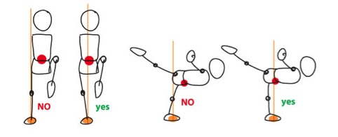
6. To maintain balance while performing static walking, a head and tail shall be implemented to the chassis of the Velociraptor to even out the shifted weight when standing on one leg and thus meet the Project Level 1, requirement 4.

maintain balance pic

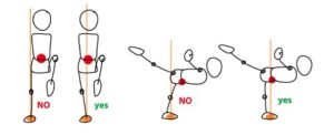
Figure 1:  http://design.tutsplus.com/articles/human-anatomy-fundamentals-balance-and-movement–vector-20936

Verification [6]:  Figure 1 shows, the center of mass is not supported when taking a step. Therefore, following the concepts of TITRUS III a head and tail shall be implemented to the body of the Velociraptor to shift the center of mass onto the foot so that it can maintain balance while walking.

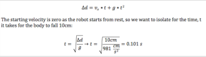
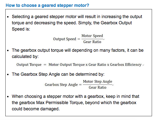
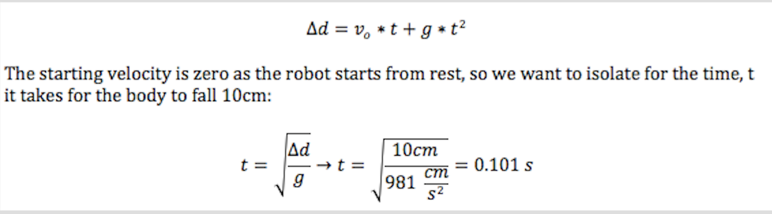
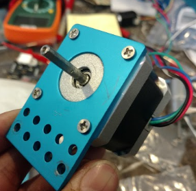
7. For the Velociraptor to perform dynamic walking servos moving at a speed of 0.101 sec/12.5° shall be implemented to the chassis and thus meet the Project Level 1, requirement 5.

Verification[7]: Assuming that the legs of the Velociraptor will not exceed 10 cm in length, using physics equations we can estimate the time each leg of the Velociraptor has to perform a dynamic step:

Screen Shot 2016-03-31 at 8.10.17 PM

TITRUS first step of dynamic walkTITRUS Second step of dynamic walk

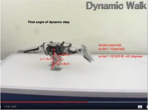
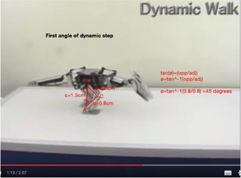
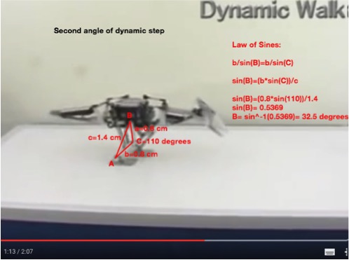
Researching TITRUS III performing dynamic walk as shown in figure 2. The angle of the right leg, performing first part of the dynamic step is calculated to 45°. The next part of the step the angle is calculated to 32.5°. Therefore subtracting these two angles we get the angle at which the TITRUS III pushes the right leg forward to perform one dynamic step to 12.5°

Therefore we estimate that the servos needed for the Velociraptor to perform dynamic walk will have to push the each leg forward at an angle of 12.5° per 0.101 seconds.

8. In order for the Velociraptor to travel on two different surfaces, the material that will be placed on the feet shall have a coefficient of friction of more than 1.0 in accordance to the Course Analysis as to refrain from slipping, and thus meet Project Level 1, requirement 3.

Verification[8]: The highest coefficient of friction of the surfaces that the Velociraptor will travel on is 1.0 from the friction between rubber and a solid.

10. In order for the robot to detect obstacles at a range of 20 cm in its path, ultrasonic sensors shall be implemented to the build of the Velociraptor and thus meeting the Project Level 1, requirement 7.

Ultrasonic sensor calc.

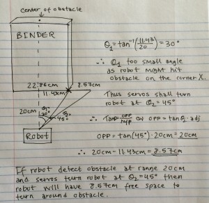
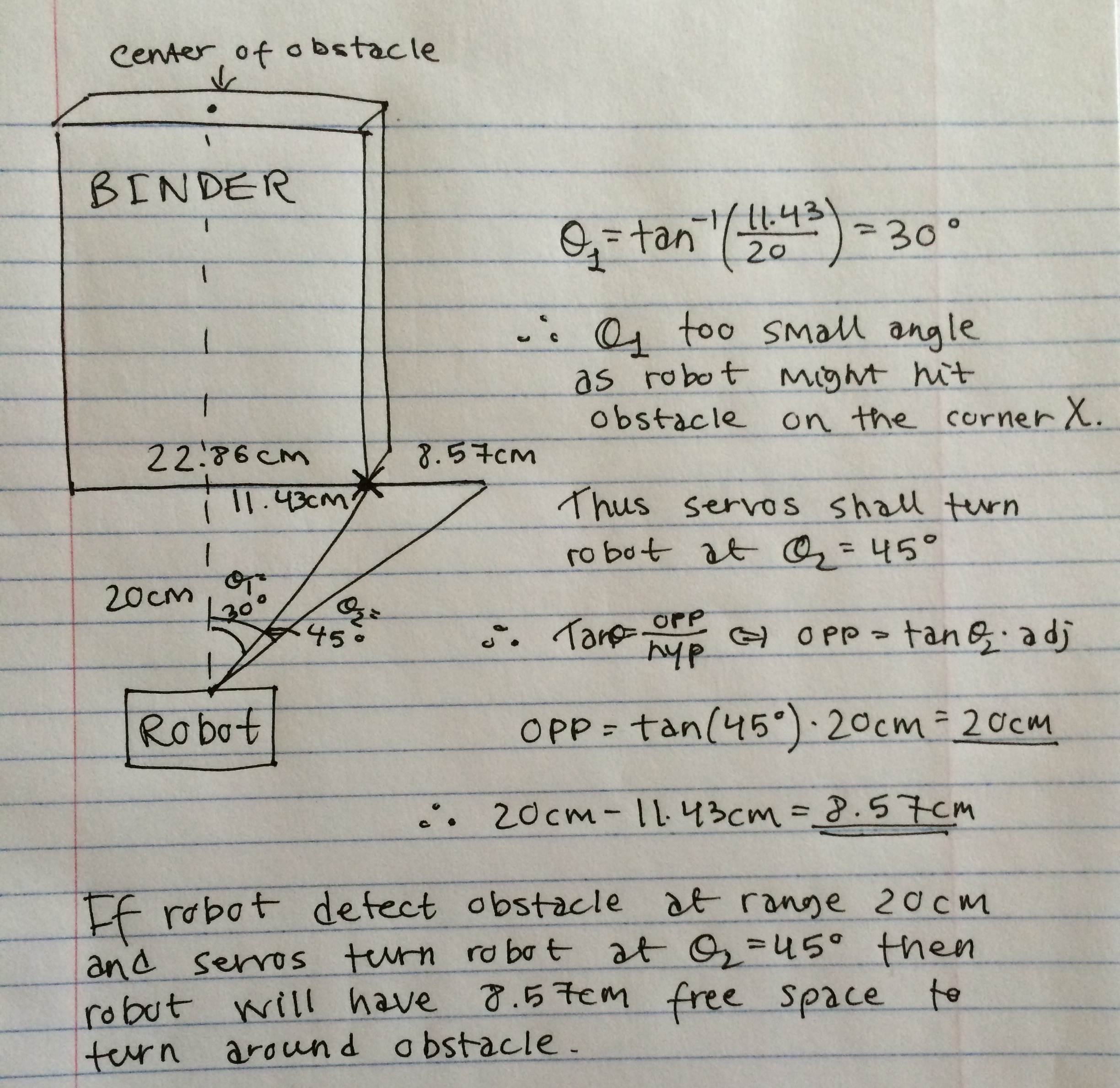
Figure 3: Ultrasonic Proximity sensor calculation

Verification[10]: The Velociraptor shall detect obstacles (Binder) at a range of 20 cm in its path in order to maneuverer around it without hitting the obstacle as calculated in figure 3 above. This requirement anticipates the servos to turn the robot at an angle of 45° rather than 30° in order to gain enough free space of 8.57 cm to maneuver around the obstacle without hitting the corner X of it.

11. To fully accommodate the movement of a turn, a total amount of 8 servos turning the robot at an angle of min. 45 ° degrees(referring back to requirement 10) to avoid obstacles shall be implemented to the Velociraptor and thus meeting the Project Level 1, requirement 8.

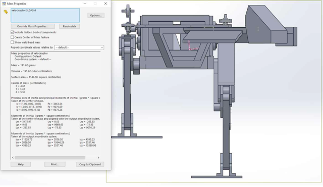
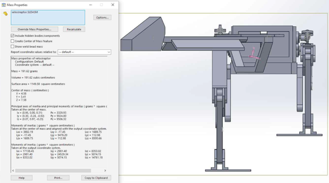
Verification[11]: An assumption of the weight of the Velociraptor’s head has been set to a total of 380g(130 g from batteries placed on the neck, 200g chassis and 50g for material for chassis of head of aluminum).

Researching from last semesters MicroBiped they used the MG92B servos which provided torque of 3.5kgcm at 6V. Dividing that with the length of the legs that will be equal to the length of neck(and tail) of 10cm equals: 3.5kgcm /10cm = 350g

This shows that one servo only provide torque enough to move a mass of 350g and not the estimated weight of 380 g for the Velociraptor’s head.

Hence this semesters Velociraptor will utilize a minimum of 2 servo per head, 2 servos per tail and 2 servos per each leg adding up to a total of 8 servos to insure that adequate torque is provided to fully accommodate the movement of a turn.

Spring 2016 3D SMD: Z-Axis Rapid Prototype


By Henry Nguyen (Electronics and Control)

Table of Contents

Introduction

For our Z-Axis, we purchased a Thread Drive Pack from Makeblock which is able to move our thread drive beam up and down with great precision. This kit came with a DC Motor; however, for our uses, we found that using a stepper motor will be more convenient and easier to control with the current software we are using. By using a stepper motor, we are able to move our Z-Axis up and down with speed and precision. Our issue is attaching a stepper motor to our thread drive pack.

Implementation

For our rapid prototyping, we will be using our X-Axis stepper motor, Me stepper driver, and our stepper motor bracket. I was able to utilize an extra bracket that came with our thread drive pack in order attach our Me stepper driver.

X-Axis Bracket

Figure 1. X-Axis Bracket

Extra Bracket

Figure 2. Extra Bracket

By connecting the extra bracket into our thread drive pack, I was able to utilize the two screws shown in Figure 2 to attach to our X-Axis bracket. The following image shows the stepper motor completely attached to our thread drive kit.

Angle 1 Installed

Figure 3. Installed Stepper Motor onto Z-Axis

Problems

When attaching the stepper motor shaft through the hole provided, I noticed that it was not completely straight. The shaft was slightly crooked due to the screws that are being attached to the brackets. This caused problems when running our stepper motor causing it to stall. By adjusting the nuts shown in Figure 3, I was able to straighten out the bracket so it became slightly more parallel to the surface.

Results

In order to test our stepper motor, we used the same code provided from our X-Axis stepper motors. We are able to use our X-axis because our stepper motor and me stepper driver came from our X-axis for this rapid prototyping. By inserting our Gcode values of X0 and X50, we were able to move at a measured distance of 0.3 inches. An example is shown in the Youtube video provided below.

https://www.youtube.com/watch?v=mQ80G-T7yP4                              

Zaxis Installed 1

Figure 4. Z-Axis Front View   

Z-Axis installed 2

Figure 5. Z-Axis Back View

Conclusion

Overall this rapid prototyping is a success. We are able to control our Z-axis thread drive kit with a stepper motor with great speed and precision all whilst being compatible with our current software. It is very easy to manipulate the distance our thread beam can move by inputting various Gcode values. I used X0 and X50 because it was able to move our 0.3 inches. Our reel feeder height is 0.17 inches. By moving 0.3 inches, it will be able to clear our reel feeder with extra space to spare. More testing will need to be done to see exactly the distance needed for our Z-axis to clear any obstacles. We will be using the shortest distance possible to increase our speed. This rapid prototyping also allowed me to visualize the design of the bracket that we will be creating in order to better fit a stepper motor onto our thread drive kit.