Spring 2016 RoFi: Battery Trade-Off Study

Christopher Andelin (Project Manager)

Mario Ramirez (Systems Engineer)

Qui Du (Manufacturing Engineer)

Andrew Laqui (Electronics and Controls Engineer)

Henry Ruff (Electronics and Controls Engineer)

Battery Trade-Off Study

Mario Ramirez (Systems Engineer)


Desired run time: 20 minutes or 0.3 hrs

Battery Life T = mAh/mA

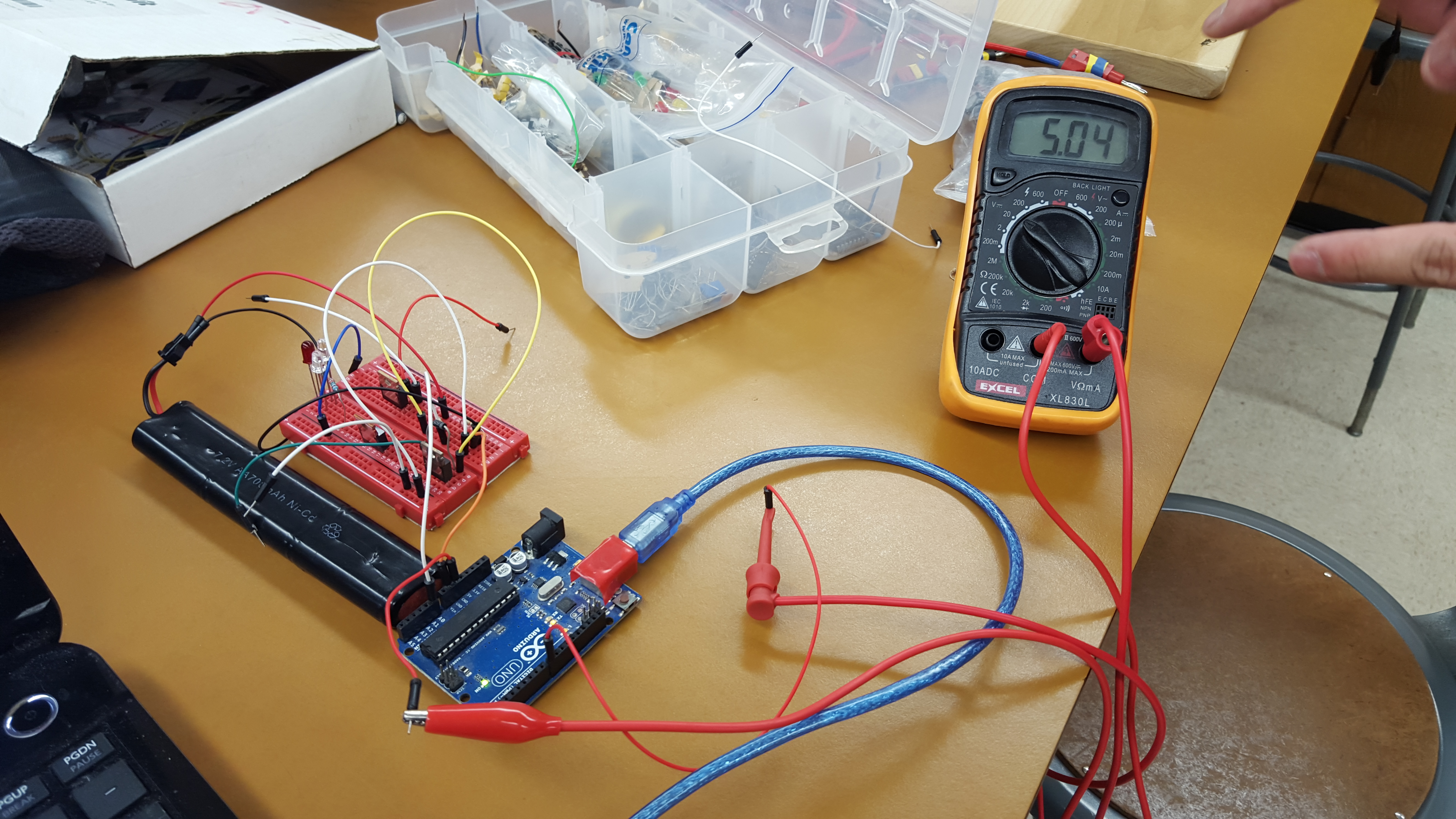
Current of one servo = 1408.315583mA

Current of all 12 servos = 16899.787mA


The power resource report, https://www.arxterra.com/spring-2016-rofi-preliminary-project-plan/#System_Resource_Reports, shows the amount of mA the system needs..  The project allocation is the amount of mA the battery will supply for 20 minutes of run time.  To find a proper battery we used the equation T=milliampere-hours/milli-ampere; where T is the amount of time in hours.  The amount of current drawn by one servo is about 1408.38583 mA and then multiplying that by 12 servos we get about 16899.787 mA. By manipulating the equation we get (16899.787mA) x (0.3 hrs) = 5069.9361 mAh which means we need a battery that can supply a minimum of 5070 mAh.  Since we will be using two batteries connected in parallel, each battery much be rated for at least 2534.96805mAh.  Our batteries voltage is of less concern because we will be using a voltage regulator.  More information on our voltage regulator is found here https://www.arxterra.com/spring-2016-rofi-voltage-regulator-trade-off-study/.

The preferred battery dimensions are  73 x 37 x 17.5mm (L x W x H);  the dimensions are obtained from RoFi’s battery slots located in his feet.  If needed, we can print a longer foot cap to allow for a longer battery instead of printing a whole new foot.

For the battery case study, we are looking for 2 batteries that are rated for 2600mAh each with the dimensions stated above.

A battery such as the VP 2600maH 7.4V Li-Po, http://www.componentshop.co.uk/7-4v-2600mah-25c-continuous-discharge-cranestock-lipo-battery.html, has the rated outputs our project needs to run for 20 minutes, but with the dimensions of 105 x 22 x 12mm.  The change in RoFi’s battery cap will be too long and interfere with RoFi’s walking capability.

From this, we have come up with three choices for our new batteries.

table 1

Table 1: Battery Comparison

Comparing all three batteries we decided the Glacier model’s thickness would not fit in RoFi’s current foot, and that printing a new foot is more difficult than finding a battery with a better fit.  Leaving the Gens Ace and Gforce models, we preferred the Gens Ace model sense we would need smaller changes in the battery cap length and .33 mm in thickness would fit properly in the dimensions of RoFi’s current foot. However, we could not find a store in the U.S. that had this battery in stock.  Therefore, we are going with the Gforce model and going to be ordering from, http://www.valuehobby.com/gforce-2600mah-2s-tx.html.


Sources

Glacier:

http://www.buddyrc.com/glacier-2600mah-2s-lipo-receiver-battery.html


Gens Ace:

http://www.hobbypartz.com/98p-2600-2s1p-2222-rx.html

Spring 2016 RoFi: Voltage Regulator Trade-Off Study

Christopher Andelin (Project Manager)

Mario Ramirez (Systems Engineer)

Qui Du (Manufacturing Engineer)

Andrew Laqui (Electronics and Controls Engineer)

Henry Ruff (Electronics and Controls Engineer)

Voltage Regulator Trade-Off Study

Andrew Laqui (Electronics & Control)

Delivering power to the servos requires a voltage regulator to transform the high voltage from the battery to a lower voltage for RoFi’s servos.

These larger voltage regulators are used instead of the much smaller voltage regulator chips because the small chips are rated for much smaller currents than what RoFi will be using. These Electronic Speed Controllers (ESC) are all rated for at least 5A. The following link details the difference between different regulators like UBEC ESCs and Opto ESCs.

http://blacktieaerial.com/opto-vs-bec-escs-use-ubec/

The following table compares the relevant specifications to determine which one will be the best for RoFi.

table 1

Table 1: Voltage Regulators

The Detrum Dynam 5A is the regulator that came with RoFi at the beginning of the semester, but after some testing and watching videos from the previous semesters, it has been concluded that this regulator did not deliver enough continuous current. According to the specifications, it was only able to deliver at the most 7.5A continuously. The RioRand® F-20A 20AMP and ARRIS Simonk 30A offer enough continuous current which will allow all twelve servos to draw their expected amount of 16.8A. This amount of current is verified by the Systems Engineer.

The following is the most updated Power Report.

table 2

Table 2: Power Report

Across the board, the RioRand® F-20A 20AMP is the preferred regulator since it is a much simpler design compared to the ARRIS Simonk 30A. Since the ARRIS Simonk 30A is an Opto ESC, it will still require an external UBEC to deliver the power to the servos.

The RioRand® F-20A 20AMP regulator was chosen mainly because it can deliver enough continuous current while also offering the simplest design. Although the Detrum Dynam 5A is already used on RoFi and the ARRIS Simonk 30A can deliver the most continuous current, the RioRand® F-20A 20AMP is relatively cheap because it can be ordered with Amazon Prime and also delivers enough continuous current.

The following are links to the websites of each respective regulator.

http://graysonhobby.com/dynam-5a-5-0v-6-0v-ubec.html

http://www.riorand.com/riorandr-f-20a-20amp-20a-simonk-brushless-esc-w-3a-5v-ubec-quadcopter-apm2.html

http://www.hobby-wing.com/arris-30a-opto-esc.html?gclid=COTjjObKwcsCFYqPfgodOV4NIQ


Spring 2016 3 DOT Goliath Laser Tag Game Safety Requirements for Children

By:  Tae Min Lee (Missions, Systems, and Testing Engineer)

We have to make sure that the level 1 requirement for safety has been addressed before we start implementing the laser tag system we will be using for our product.

Problem:

The first design of implementing the laser tag game was to use a laser module with a photo resistor as the receiver.  However, it became a problem with making the product safe for children to play with due to the following:

  1. Laser was classified as level 2
    1. Class 2 – lasers emit radiation in the visible portion of the spectrum, and protection is normally afforded by the normal human aversion response (blink reflex) to bright radiant sources. They may be hazardous if viewed directly for extended periods of time.  Ex:  Laser Pointer
  2. Most laser module power rating are 5mW, but to be considered safe it must be 1mW to be classified as level 1.
    1. Class 1 – lasers are considered to be incapable of producing damaging radiation levels, and are therefore exempt from most control measures or other forms of surveillance.
  3. Lasers are concentrated beams (visible) that passes through the cornea and focuses on one point on the back of the retina (shown in figure 1).

Tae second post 1


  1. The concentrated laser beam cause damage to the cornea, retina, and the lens (figure 2).
    1. Visible (400 – 760 nm Wavelength)
      1. Most of the radiation is transmitted to the retina.
      2. Overexposure may cause flash blindness or retinal burns
    2. Quick Calculation of the magnification of the damage to the eye:

Conclusion:  Laser retinal injury can be severe because of the focal magnification making it dangerous to implement a laser module for the laser tag game.

Tae second post 2


Solution:

To make a product that is safe for children to play with we implemented the use of IR LED emitter for the laser tag game.  The safety requirements for the Goliath using IR emitter will be stated below:

  1. Emitter must not produce enough radiation that brings harm to the eyes
  2. Emitter will not produce a highly concentrated beams that will damage the retina (figure 1).
    1. IR LED is non-visible light that doesn’t pass the cornea making it safe


Tae second post 3


Sources

  1. https://web.stanford.edu/dept/EHS/prod/researchlab/radlaser/laser/procedures/classes.html
  2. http://www.fda.gov/ForConsumers/ConsumerUpdates/ucm363908.htm#lasers
  3. http://oregonstate.edu/ehs/laser/training/laser-biological-hazards-eyes

Spring 2016 3 DOT Goliath IR Emitter/Receiver Test

By: :  Tae Min Lee (Missions, Systems, and Testing Engineer)

Tae 2


IR Mid-Range Proximity Sensor

Implementing a game of laser tag using IR emitter/receiver will be safe for to play for all ages.  This falls back to one of our level 1 requirements for safety standards for child safe toys.  The figure above shows the connections for the sensor for the following:

  1. Output
  2. Ground
  3. Vcc


Components Used:

  • Arudino Uno
  • IR LED (Remote Control)
  • x3 Red LED
  • BreadBoard
  • Wiring Kit
  • x2 220 ohm resistor

The affective distance of the detector and the IR LED was measured to be around 1.85 meters.    The distance was determined by using a remote control that has a IR LED emitter that was aimed at the sensor.  We had a red LED to detect when the IR sensor gets hit by the remote control.  The laser tag game will have a rule for the first 3 hits will declare the winner (figure seen below).

Tae pic


Sources:

  1. http://www.vishay.com/docs/82474/tssp4p38.pdf
  2. http://www.instructables.com/id/IR-Detector/


Spring 2016 Pathfinder: Bluetooth Communication with the Arxterra App

Bluetooth

By: Xiong Lee (Systems Engineer)

Table of Contents

Introduction to Arxterra App:

We first had to download the Arxterra App by emailing Jeff Gomes to give us the invitation to download Arxterra. The app has two modes we can access. The first one is remote control and the other is community. The remote control mode allows us to control the movement of the pathfinder from the Arxterra app on your phone. The community mode allows us to control the pathfinder through the control panel online found here. For our purpose, we wanted to be able to communicate with app via bluetooth so we used the remote control mode to show Bluetooth connection. To learn more about the features of the app, the video is shown here.

Code:

The code that was used to test the Bluetooth connection to the Arxterra app is found here. This code was the latest code we could find that was used for this pathfinder. There was trouble having the code work. The first problem we came up with was not having all the library files so the code could not compile. The files that we needed in the library was found on GitHub and was implemented into our Arduino IDE library. The libraries on GitHub can be found here. To add libraries to the arduino, you can go here.

Debugging the code:

     if (cmd == MOVE) {

       /***********************************

       * motion command = 0x01

       * motordata[3]   left run    (FORWARD = index 1, BACKWARD = index 2, BRAKE = index 3, RELEASE = index 4)

       * motordata[4]   left speed  0 – 255

       * motordata[5]   right run   (FORWARD, BACKWARD, BRAKE, RELEASE)

       * motordata[6]   right speed 0 – 255

       * example

       * forward half speed  0x01, 0x01, 0x80, 0x01, 0x80 0101800180

       ***********************************/

       /*

       WARNING

       WARNING ONLY THE TB6612FNG HAS BEEN UPDATED WITH NEW INDEX ADDRESSES

       WARNING Typically all you need to do is add 2 to the index (1 -> 3, 2 -> 4, etc.)

       */


         // Pololu VNH5019 motorshield (Pathfinder)

//          move_VNH5019(data);


       //collisionDetection = (data[1] == 1) || (data[2] == 1);  // set to true if any motor is moving forward

     }


After finding all the libraries that we needed, we uploaded the code to the microcontroller. When testing the code, it did not move at all. From the picture above, we can see that the app is sending command packets to the arduino, but it is still not moving. So in conclusion, we knew that the code was not decoding the commands correctly and had to run over the code and debug it.


While running through the code, we found out that the move command was not being called in the command tab. When going to the move command, there was no command there to tell the pathfinder what to do because we have the pololu VNH 5019 motor shield on the pathfinder. The move routine was commented out and not calling the pathfinder to move. So after uncommenting this command (the code highlighted in red above), we also needed to uncomment the move subroutine on the first tab (arxrobot firmware).


//void move_VNH5019(uint8_t * motordata)

//{

//  int m1Speed = dirArray[motordata[1]] * motordata[2]; // left motor

//  int m2Speed = dirArray[motordata[3]] * motordata[4]; // right motor

//  md.setSpeeds(m1Speed, m2Speed);

//}


Another problem with the code was in the move_VNH5019 routine. The motordata[ ] should be in the order of 3,4,5,6. So instead of the code you see up there, it should be


 int m1Speed = dirArray[motordata[3]] * motordata[4]; // left motor

 int m2Speed = dirArray[motordata[5]] * motordata[6]; // right motor

 md.setSpeeds(m1Speed, m2Speed);


Bluetooth connection on Arduino board:

Their Bluetooth chip (HC-06) was connected on the previous pathfinder’s custom  PCB. In the code, the ports that the Bluetooth chip is reading on the Arduino board was the serial port 2. This means that the Bluetooth chip need to be connected to the RX2 and TX2. Since the chip was on the PCB, we couldn’t tell if it was connected to the right port and so we decided to disconnect the PCB and jump wire the Bluetooth to the ports using a breadboard instead.


Conclusion:

Another error came into factor when we still couldn’t get it to work. The other error was that the batteries were low and couldn’t run the motors. So we charged the batteries and after doing all the debugging and rewiring, we finally got the arxterra app to work via bluetooth. We made the pathfinder move using the remote control mode. The things we learned were to not expect the codes to work right away. We had to learn how the commands were transferred through the app and how it was decoded. We had to assume the bluetooth chip was not connected to the RX2 and TX2 pin because we couldn’t tell if their custom PCB was working properly. In the end, we were able to get the Bluetooth connection to work with the Arxterra App.


Source Materials:

http://arxterra.com/control-panel/  

https://www.youtube.com/channel/UCJXZGMpv8GqxkOi6W02GzoQ

https://github.com/arxterra

http://arxterra.com/pathfinder-axterra-gps-communication-part-three/

https://www.arduino.cc/en/Guide/Libraries

Spring 2016 A-TeChToP ATBTLC1000 Testing

By: Rose Leidenfrost (Electronics Engineer)

Purpose

The purpose of this experimentation was to identify example applications for the ATBTLC1000 and determine which parts might be useful for software program subroutines. The example code used is also provided.

Read more

Spring 2016 RoFi: Power Trade-Off Study

Christopher Andelin (Project Manager)

Mario Ramirez (Systems Engineer)

Qui Du (Manufacturing Engineer)

Andrew Laqui (Electronics and Controls Engineer)

Henry Ruff (Electronics and Controls Engineer)

PTC Trade-off Study

Henry Ruff (Electronics & Control)


In the schematic design for RoFi, the PCB mainly entails connections to the main four components: bluetooth, accelerometer/gyroscope, ultrasonic sensor, and servos. For the twelve servos in particular, each one needs a polymeric positive temperature coefficient (PPTC) fuse, in order to protect them from drawing too much current at stall conditions. These PTC fuses can be implemented on the PCB itself, and for this purpose, several surface mount varieties were compared. The company Littelfuse provided the following guide for comparing potential components, and only the surface mount series were considered in this study. Datasheets for specific components within each series were found in the second link.


http://www.littelfuse.com/~/media/files/littelfuse/technical%20resources/documents/product_brochures/ec327-e_polyfuse_ptc.pdf

http://www.littelfuse.com/products/resettable-ptcs/surface-mount.aspx


The following table is a basic trade-off between the available series of PTC fuses, such that each series can be further looked into afterwards for a more specific trade-off series.

table 1

Table 1: Pros and Cons

The hold current (IHOLD) is the normal operating current of the servo, which for the PowerHD 1501-MG is 500mA at 6V, although ideally the servos will be supplied with 5V. The trip current (ITRIP) is where the PTC fuse will begin to impede excess current, desirably chosen to be less than the servos’ stall current of 2500mA at 6V. After looking at the cons, the 1206L, 1210L, 1812L, 2016L, and 2920L series were looked at for comparison, using components that would be the closest match for desired purposes. IHOLD would be up to around 1A to allow for variation due to operation and load, while ITRIP would be under 2500mA. For the following table, each component had functionally the same pros, therefore only cons and price were compared.

table 2

Table 2: Cons and Price

Mainly due to price comparisons, the Littelfuse 1206L110TH was then chosen from this study to be used on the PCB board.  However, higher numbered series had trip times up to 0.5 seconds as opposed to the 1206L110TH which had a trip time of 0.1 seconds, and was better because of which.

Spring 2016: 3DoT Spider-Bot Alternative Printing for Small Parts.


BY:
Andrew Saprid ( manufacturing engineer)

After building the main parts of the 3Dot David in Solidworks, they were too small to 3D print. For the moment, it is the main problem for building and assembling the model. The picture below shows the quality of the 3D printed parts compared to the original parts. Because of the low quality of the printing, alternative methods were researched.

compare

 CNC Machine

CNC machining is a process used in manufacturing that involves the use of computers to control machine tools. CNC stands for computer numerical control. With the computer, it can control exact positioning and velocity from a computer program that customizes an object.

A 2D or 3D drawing is created from a CAD program and then a code is created that the CNC machine will understand. The process is more precise than manual machining, and can be repeated exactly the same manner.  

Screen Shot 2016-03-11 at 11.39.22 AMScreen Shot 2016-03-11 at 11.39.51 AM


The shopbot product on their site is a tool that precisely cuts, carves, and drills any machinery material. The figure below indicates a x and y axis for cutting material in either the x or y directions.

Screen Shot 2016-03-11 at 11.40.23 AM


Advantages Disadvantages
Printing small parts will provide exact replica of the drawing made from CAD/CAM program. If not proficient with CAD/CAM, then it will take 2 weeks to learn, which will take longer to learn the g code. It will take time and patience.
Fast Production Need to buy materials, which could increase the cost

Laser-cutting machine

Screen Shot 2016-03-11 at 11.41.00 AM
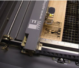
Laser-cutting will cut designs to create in most graphic software programs. Instead of laser printing paper, the machine will fire C02 laser beam that will cut through the material.

  • The C02 laser provides 30 – 120 watts of power
  • Engraving materials: wood, acrylic, glass, leather, corian, fabric, coated metals, anodized aluminum, stone, marble, ceramics, mylar, etc.
  • Cutting materials: wood, acrylic, plastic, delrin, cloth, leather, melamine, paper, rubber, veneer, cork, etc.

The Advantages of C02 Laser Cutting

  • The laser creates a beam of light that is used to cut through the material.
  • For thinner materials, all Epilog laser systems include an integrated vacuum table to hold down papers, fabric, and thin plastics as it cuts through the material.
  • It is very precise, following the design
  • Cut several patterns from the same piece of material.
  • Can be printed to the laser from variety of programs that include CorelDRAW, AutoCAD, and Adobe software

Molding and Casting

Although all are parts shall be 3D printed, this is the last resort, if 3D printing cannot print small parts.

One of the first steps is to design a mold in Solidworks to produce the parts.Screen Shot 2016-03-11 at 11.41.30 AM

When making a part, there should be a way for any air in the mold to be pushed out. This shows the flow of resin.Screen Shot 2016-03-11 at 11.41.52 AM

When casting the parts, according to the blogger, his favorite resin supplier is Smooth-On. It is very strong and flows wells into tiny parts. The cost is $27. The materials will be enough to make hundreds of the parts.Screen Shot 2016-03-11 at 11.42.27 AM

When making the perfect part, it is put inside the pressure pot because of the air bubbles the resin produces in the part. It is pressurized to 60 PSI using an air compressor, which eliminates air bubbles.

This is the last resort if any of the methods of printing small parts is not working. The reason this is the last resort is because COST is the issue. But the advantage of molding will make lives easier when replicating a part, making production faster.

Here are the materials he used:

-Solidworks

-MeshCAM CAM Software

– Delrin Sheets for the molds $6.84-$878.56 on Amazon

-Pipettes $2.98-$15.73 on Amazon

-Smooth-On task 3 Resin $26.41 on Amazon

-Smooth-on 200 Release Agent $13.20 on Amzon

-Smooth-On Pressure Pot

Stereolithography
Screen Shot 2016-03-11 at 11.56.12 AM

This is a technique for creating 3D objects, in which a computer-controlled moving laser beam is used to build up the required structure, layer by layer from a liquid polymer that hardens on contact with laser light.

Advantages Disadvantages
Parts can be shortly Can be expensive depending on which company service it provides
Creates smoother surfaces Companies have charged $30/hour
Smoother surfaces mean high level design detail and will be accurate SLA machine equipment can cost between $100,000 and $400,000
Size doesn’t have to be an issue Simple small finished prototype starts at $100
have lots of finish options

Companies that offer services for Stereolithography:

  • Quickparts
  • Ponuko
  • Shapeways
  • 3D
  • Scicon Technologies


References:

CNC Machine

http://www.thomasnet.com/about/cnc-machining-45330503.html

http://www.datron.com/Small_Part_Machining.htm

http://www.shopbottools.com/mproducts/whatscnc.htm

http://blog.cnccookbook.com/2012/02/22/10-things-beginning-cnc-milling-machine-users-need-to-succeed/

Laser Cutting Machine

https://www.epiloglaser.com/laser-cutting/laser-cutting.htm

Molding and Casting

http://www.machinistblog.com/casting-small-parts/

Stereolithography/SLA printing

http://www.intechrp.com/advantages-of-stereolithography/

http://intermag-modelex.com/advantages-and-disadvantages-of-laser-stereolithography/

http://www.designboom.com/technology/low-cost-stereolithography-3d-printer-by-formlabs/

http://www.cs.cmu.edu/~rapidproto/students.02/sstille/project2/sla.html

http://honeybuild.com/guides/stereolithography

http://scicontech.com


Spring 2016 Pathfinder Charging Control Circuit

20160308_161724

by: Tuong Vu (Sensors, Actuators and Power)

Table of Contents

Introduction:

This document is to explain the charging control circuit of the pathfinder. The customer wants the pathfinder to have a self-charge capability. This circuit will help regulate voltage and circuit during the charging time of the batteries by the solar panel. The purpose is to prevent the damage to the batteries from overcharging.

Electronic Components:

  • 2 X resistors 1k ¼ watts
  • solar panel : NPower Amorphous Solar Panel Battery Maintainer Kit – 2.5 Watts
  • 2 X batteries : 10000MAh lead Battery
  • N- channel IRF840

Understand Components:

circuit

Figure 1

  According to the diagram above, two pins are reserved for this circuit from the Arduino, specifically   one analog pin and the other digital pin.  Analog pin is used for the intake voltage data from the voltage divider.  We implement the voltage divider to prevent damaging the I/O pins on the arduino, see table 1.  Ideally  the mosfet acts like switch such when voltage into the gate is much higher than the threshold voltage, the mosfet turns on, which means the drain and source  pins  are in series together. Arduino can generate a 5 volts output, which is enough to turn the mosfet on. When the  drain and source are connected the solar panel  is directly in  series with  the battery, allowing the current to flow and effectively charging the battery.

circuit1

The batteries and the solar panel switch place


Arduino Code:

Code  generates a  sequence of  addition   of  input voltage  taken from the  voltage divider,  which  will  go through  an if statement  in order  to   turn  the  Mosfet  on.

/*————————————————————–

Program:       Volt_measure

Description:  Reads value on analog input A2 and calculates

The voltage assuming that a voltage divider

Network on the pin divides by 11.


Hardware:     Arduino Uno with voltage divider on A2.

Software:      Developed using Arduino 1.0.5 software

Should be compatible with Arduino 1.0 +

Date:             22 May 2013

Author:          W.A. Smith, http://startingelectronics.org

————————————————————–*

// number of analog samples to take per reading

#define NUM_SAMPLES 10

int sum = 0;                // sum of samples taken

unsigned char sample_count = 0; // current sample number

float voltage = 0.0;                  // calculated voltage

int r8 = 8;

void setup()

{

Serial.begin(9600);

pinMode(r8,OUTPUT); // output pin.

}

void loop()

{

// take a number of analog samples and add them up

while (sample_count < NUM_SAMPLES)

{

sum += analogRead(A0);

sample_count++;

delay(10);

}

// calculate the voltage

// use 5.0 for a 5.0V ADC reference voltage

// 5.015V is the calibrated reference voltage

voltage = ((float)sum / (float)NUM_SAMPLES * 5.015) / 1024.0;

// send voltage for display on Serial Monitor

// voltage multiplied by 11 when using voltage divider that

// divides by 11. 11.132 is the calibrated voltage divider

// value

Serial.print(voltage * 11.132);

Serial.println (” V”);

sample_count = 0;

sum = 0;

if  (voltage < 4)

{

digitalWrite(r8,HIGH);

//delay(5000);

}

else if ( voltage > 4)

{

digitalWrite (r8,LOW);

//delay(5000);

}

}

//delay(100000)    .

This code was written by W.A. Smith, but is modified with the if statement by us. The Arduino is taking samples and applying them through the equation in the code ( see code) thus gives the voltage increment  we need. The output voltage generated by the arduino is the 8  digital pin,  this is where  the mosfet going to get the voltage to turn on or off.

table

figure 2 ATmega 328P specifications

Test results

result1

The above picture shows that the battery has 5.04 V before charging

result2

This picture shows that the battery now has 7.77 V after charging

Source Materials:

Arduino: Read Analog Voltage click here

NASA: How do Photovoltaics Work? click here

Spring 2016 RoFi: Servo Testing and Centering

Christopher Andelin (Project Manager)

Mario Ramirez (Systems Engineer)

Qui Du (Manufacturing Engineer)

Andrew Laqui (Electronics and Controls Engineer)

Henry Ruff (Electronics and Controls Engineer)

Servo Testing and Centering

Henry Ruff (Electronics & Control)


Considering RoFi’s provided condition is questionable, we decided to verify that each servo was still in working condition, and able to perform in its given ranges. The servos being used are the Power HD 1501-MG, and the datasheet for which is provided below.


https://www.pololu.com/file/download/HD-1501MG.pdf?file_id=0J729


According to this datasheet, each servo has a range of motion of 165 degrees, and so for our purposes I modified the following code to sweep the servo arm in a range of 0 to 180, pause, and then sweep back from 180 to 0. This test was performed on each servo individually, using the schematic and setup provided below as well.

ServoTest_compressed

Image 1: Servo Test

ServoCentering

Image 2: Servo Centering

/* Sweep

by BARRAGAN <http://barraganstudio.com>

This example code is in the public domain.


modified 8 Nov 2013

by Scott Fitzgerald

http://www.arduino.cc/en/Tutorial/Sweep


Modified By Henry Ruff

*/


#include <Servo.h>


Servo myservo;  // create servo object to control a servo

// twelve servo objects can be created on most boards


int pos = 0;    // variable to store the servo position


void setup() {

myservo.attach(5);  // attaches the servo on pin 5 to the servo object

}


void loop() {

for (pos = 0; pos <= 180; pos += 1) { // goes from 0 degrees to 180 degrees

// in steps of 1 degree

myservo.write(pos);              // tell servo to go to position in variable ‘pos’

delay(15);                       // waits 15ms for the servo to reach the position

}

delay(2000);

for (pos = 180; pos >= 0; pos -= 1) { // goes from 0 degrees to 180 degrees

// in steps of 1 degree

myservo.write(pos);              // tell servo to go to position in variable ‘pos’

delay(15);                       // waits 15ms for the servo to reach the position

}

delay(2000);

}

The results of running the code for each servo is shown below. The numbers assigned to each servo was for testing purposes only, and differs from how they are actually assembled into RoFi. Servos that did not perform as expected were noted as such, and therefore set to be replaced if necessary.

ServoTable

Table 1: Servo Results

Modification to this code (shown below) was used to center the servos, following the method that Jonathan Dowdall outlines on his Project Biped website. Once a servo is centered by using the code, it is assembled into RoFi using the image below that is also on the website, and is then ready to be used in other steps.

ServoAssembly

Image 3: Servo Assembly Source:https://docs.google.com/presentation/d/1bLCdCVLSEdNJ1TqWfmgMjQWJXn9XuLbbaKUQzWxhx_E/edit?pref=2&pli=1#slide=id.i6


/* Sweep

by BARRAGAN <http://barraganstudio.com>

This example code is in the public domain.


modified 8 Nov 2013

by Scott Fitzgerald

http://www.arduino.cc/en/Tutorial/Sweep

*/


#include <Servo.h>


Servo myservo;  // create servo object to control a servo

// twelve servo objects can be created on most boards


int pos = 0;    // variable to store the servo position


void setup() {

myservo.attach(5);  // attaches the servo on pin 5 to the servo object

}


void loop() {

for (pos = 0; pos <= 90; pos += 1) { // goes from 0 degrees to 180 degrees

// in steps of 1 degree

myservo.write(pos);              // tell servo to go to position in variable ‘pos’

delay(15);                       // waits 15ms for the servo to reach the position

}

delay(20000);

}