Spring 2016 Pathfinder Design and Manufacturing – Tilt System Design

tilt system

By: Lindsay Levanas (Design and Manufacturing)

Table of Contents

Introduction

In view of the fact that Spring 2016’s Pathfinder will utilize both a Google Tango tablet and a phone as the main viewing system,1 the tilt system will be primarily designed around these two objects. Note that the pan system already in place on the current Pathfinder design will remain, allowing for the tilt system to be added on to it to form a complete pan and tilt system.

Tablet Encasement

As stated in the level 1 requirements, the Google Tango tablet must be encased for it’s own protection.1 To allow the user access to the tablet, a box with lid design was chosen, with the lid having a cut-out window for the tablet’s primary sensors. Measurements for the tablet are as follows:

Height: 4.72 in

Width: 7.73 in

Depth: 1.5 in

Note that the height and width measurements came from the tablet’s specifications.2 The depth however had to be measured as the tablet’s back shape is uniquely slanted as seen below in Figure 1 and 2.

figure1

Figure 1
figure2

Figure 2

Therefore to allow for the tablet sensors to aim forward, the flat side of the sensors needs to be aligned with the phone and the resultant distance between the two measured. While slightly difficult to accurately document, Figure 3 and 4 attempts to pictorially illustrate this.

figure3

Figure 3figure4

Figure 4

Therefore, the inside depth of the tablet box is 1.5in.

Next the placement of the necessary sensors on the tablet must be measured so that the cut-out window in the lid can be properly placed. Using Figure 5, 6 and 7 as a guide, the sensors were found to be enclosed in a rectangle 1.6 inches from the tablet’s side edges and .8 inches from the top.

figure5

Figure 5figure6

Figure 6figure7

Figure 7

Lastly, to ensure that the tablet fits into the box, .02 inches was added to both sides of the height, width and depth totals while the thickness of the box was chosen to be .23. Therefore, the tablet box (with lid) measurements are as follows:

Inside                               Outside

Height: 4.76in                                5.22in

Width: 7.77in                                 8.23in

Depth: 1.54in                                  2in


Phone Encasement

Similar to the process used above, the box for the phone was designed around the measurements listed in the body specifications.3 Adding the same extra room as the tablet for the phone to fit and the same box thickness, the dimensions become as follows:

Inside                                Outside

Height: 5.69in                                6.15in

Width: 2.82in                                 3.28in

Depth: 0.31in                                  .77in

Again following the same procedure for the lid cut-out as was done for the tablet, the camera hole was found to be a .68in square centered 1.41 inches down from the center top of the lid. Figure 8 and 9 were used for reference.

figure8

Figure 8figure9

Figure 9

Attaching the tablet and phone

To line up the phone’s camera with the tablet’s sensors, the two encasement boxes share circular cut-outs for screws to hold them together. For the tablet box, this means 2 screw holes on the top and bottom edge centered 1.645 inches from the top center of the box. For the phone box, this means 2 screw holes on the sides centered .5 inches from the top and 2 screw holes on the sides centered 5.725 inches from the top. When all aligned, the phone’s camera and the tablet’s sensors will now be on the same level.


Swivel point

For the phone and tablet box (hereafter referred to as tilt box) to be able to tilt, the midpoint of the system needs to be found. Taking into account the height of the tablet box and the width of the tilt box, a cylindrical extrusion is added to one side of the tablet box 1.64 inches deep from the back. Mirroring this, the other side will contain two holes of equal distance apart from the same center point so that a servo can be attached.


Tilt base

To hold both the servo and tilt box, a base is needed to connect the two sides. The width of this base will vary depending on the servo used, but the height is based on the height of the pan servo already attached to the current Pathfinder, as the tilt system will be structured around it. Considering a sample servo of width 1.75 inches, the base of the tilt system should be at least 10.48in (the width of the servo + the width of the tablet box). The height should be at least 2.125 inches from base to phone box in order to clear the pan servo.


Finished Product

figure10

figure11


Source Material

  1. Spring 2016 Pathfinder Preliminary Design Documentation, Level 1 Requirement, 2/19/16 http://arxterra.com/spring-2016-pathfinder-preliminary-design-documentation/
  2. Project Tango Development Kit User Guide, Technical specifications, 8/6/2015 https://developers.google.com/project-tango/hardware/tablet#technical_specifications
  3. Samsung Galaxy S6 – Full phone specifications, Body, http://www.gsmarena.com/samsung_galaxy_s6-6849.php

Spring 2016 3 DOT Goliath Bluetooth Module HC-06 Test

Goliath Bluetooth Module HC-06 Test

By:  Tae Min Lee (Mission, Systems, and Testing Engineer)

One of the requirements of the Goliath was using the Arxterra Control Panel and the Arxterra application.  Since, the 3Dot board was not given at the time we had to find an alternative to test the Bluetooth module (HC-06).  Before we start using the Arxterra application we performed a basic test on the Bluetooth module.  The purpose of this test was to determine the communication between the Bluetooth module and the android device.

first


We used an android application called BlueStick Control on an android phone.  The following code shown above was uploaded to the Arduino Uno along with the Bluetooth module.  By pressing the up key the serial monitor returned a string value 8 corresponding to the key that was just pressed.  The next string value 4 corresponds to left, string value 2 corresponds to down and string value 6 corresponds to right.  The zero value shows the default string value it returns to as the user lets go of the key (shown above).

The tutorials to test the Bluetooth module came from instructables to test out the basic functions of a Bluetooth module.  We performed a test of the code to see the communication between the Arduino Uno with the HC-06 Bluetooth module.  We tested to determine the output interface for our lasers and motor control.

Components Used:

  • Bluetooth Module (HC-06)
  • Wiring Kit
  • Arduino Uno
  • Motor
  • Laser Module
  • Arduino IDE
  • Arduino Motor Shield


The following circuit shown below was used to test the laser shot control using an Arduino Uno, laser module, and the Bluetooth module.

seconed


Modifying the code shown earlier we can control the laser shots by pressing a button from our android device that will be communicating with the Arduino Uno through a Bluetooth Module. See the following code:


3rd


The code will set the laserPin HIGH (turn on laser) when the button with the string character ‘F’ is pressed.

The next test was performed to see if the android device was able to communicate with the Bluetooth Module that was connected with both the Arduino Uno and the Arduino Motor Shield (shown below).

4th

The following code will be used to implement the motor control that will be used on the Arduino Uno and the Arduino Motor Shield:


const int  //Declaring all the pins used for motor 1 and motor 2

//Motor 1

PWM_A = 3,

DIR_A = 12,

BRAKE_A = 9,

SNS_A = A0,


//Motor 2

PWM_B = 11,

DIR_B = 13,

BRAKE_B = 8,

SNS_B = A1,

laser = 6;


void setup()

{

// Intializes the output and input for the pins

pinMode(BRAKE_A, OUTPUT);

pinMode(DIR_A, OUTPUT);

pinMode(BRAKE_B, OUTPUT);

pinMode(DIR_B, OUTPUT);

Serial.begin(9600);

}


void move()

{

digitalWrite(BRAKE_A, LOW);   // settig the brake LOW to disable motor brake

digitalWrite(DIR_A, LOW);     // now change the direction to forward setting LOW the DIR_A pin

analogWrite(PWM_A, 250);

digitalWrite(BRAKE_B, LOW);   // now change the direction to forward setting LOW the DIR_B pin

digitalWrite(DIR_B, LOW);

analogWrite(PWM_B, 250);

}


void brake()

{

digitalWrite(BRAKE_A, HIGH); //Sets the brakes for both motor 1 and motor 2

digitalWrite(BRAKE_B, HIGH);

}


void backward()

{

digitalWrite(BRAKE_A, LOW);  // setting againg the brake LOW to disable motor brake

digitalWrite(DIR_A, HIGH);    // now change the direction to backward setting HIGH the DIR_A pin

analogWrite(PWM_A, 250);


digitalWrite(BRAKE_B, LOW);  // setting againg the brake LOW to disable motor brake

digitalWrite(DIR_B, HIGH);    // now change the direction to backward setting HIGH the DIR_A pin

analogWrite(PWM_B, 250);

}


void turnRight()

{

digitalWrite(BRAKE_A, LOW);  // setting againg the brake LOW to disable motor brake

digitalWrite(DIR_A, HIGH);    // now change the direction to backward setting HIGH the DIR_A pin

analogWrite(PWM_A, 250);


digitalWrite(BRAKE_B, LOW);  // setting againg the brake LOW to disable motor brake

digitalWrite(DIR_B, LOW);    // now change the direction to forward setting LOW the DIR_A pin

analogWrite(PWM_B, 250);

}


void turnLeft()

{

digitalWrite(BRAKE_A, LOW);  // setting againg the brake LOW to disable motor brake

digitalWrite(DIR_A, LOW);    // now change the direction to forward setting LOW the DIR_A pin

analogWrite(PWM_A, 250);


digitalWrite(BRAKE_B, LOW);  // setting againg the brake LOW to disable motor brake

digitalWrite(DIR_B, HIGH);    // now change the direction to backward setting HIGH the DIR_A pin

analogWrite(PWM_B, 250);

}


void stop()

{

digitalWrite(BRAKE_A, HIGH);

digitalWrite(BRAKE_B, HIGH);

}


void loop()

{

// put your main code here, to run repeatedly:

char ch = Serial.read();

Serial.print(“Received: “);

Serial.println(ch);


if (ch == ‘8’) //Move forward

{

move();

delay(1000);

stop();

}

}


The code shown above will only implement the move forward function by calling on the sub routine move.  By adding else if statements we can implement a turn right, turn left, or backwards.

The overall pins that we will be using on the Arduino Uno is shown below:

las


Sources:

  1. http://www.instructables.com/id/Add-bluetooth-to-your-Arduino-project-ArduinoHC-06/
  2. https://www.arduino.cc/en/Main/ArduinoMotorShieldR3
  3. https://www.arduino.cc/en/Reference/DigitalWrite


Spring 2016 3DOT Goliath Laser vs. IR LED Trade-Off Study

By: Kevin Moran (Electronics and Control Engineer), Tae Lee ( Systems Engineer)


Screen Shot 2016-03-07 at 7.46.58 PM


Our team’s mission is to decide the better approach for a game of laser tag, either by using lasers and light detecting sensors, or by using IR Receivers and LEDs. From the research we concluded on proceeding to test Photo-resistors and lasers for our game of game tag. The reason being that the laser has a longer range to activate the resistor, over 14 meters more than the IR that was tested. The laser can hit targets further, because the light emitted is concentrated on a single focus and wavelength (for the most part) and then transmitted. The IR LED diffuses its wavelength, sending it in all directions. In order to achieve this game using IR receivers, the range will have to be too short and the IR LED must be able to concentrate its light on the target. The laser requires less operating voltage than the IR receiver, and that is an advantage since we are trying to keep our current dissipation to a minimum.

The laser and photo-resistor were tested using an Arduino circuit, and the Plot function in order to observe its behavior in the presence of the laser and of natural light.

Screen Shot 2016-03-07 at 7.47.58 PM

Laser test results:

When testing the laser and its receiver, it was necessary to ensure the photo-resistor would not activate under normal light conditions. When a laser light was not focused on the target, the graph showed a flat line very close to the zero value. When the laser was aimed, the graph peaked. It was noted that the peaks increased if the laser was aimed for a longer amount of time. 1 second provided us with the taller peaks in the graph. This analog signal we are obtaining must be converted to Digital in order for receiver to activate regardless of the amount of time the laser aims to it.


Recommendation:

If the laser is to be powered the 3DoT board, this board must be able to supply the 40 mA that the laser requires. When tested with and Arduino, it was noted that this board only provided an output of 20 mA. I recommend to either use a smaller laser that requires less than 20 mA to operate, or to build a PCB with a circuit regulator in order to ensure the laser works as it is intended.


Sources:

http://www.plaintree.com/pdf/DataSheets/Plaintree’s%20LED%20vs%20LaserNEW.pdf

http://www.farhop.com/product/farhop-5-volt-5mw-650nm-red-dot-laser-diode-module-5-pieces/

http://www.digikey.com/product-detail/en/350-00009/350-00009-ND/1774434


Spring 2016 3DOT Goliath DC Motor Trade-Off Study

By: Kevin Moran (Electronics and Control Engineer)

Screen Shot 2016-03-07 at 7.41.15 PM

After carefully reviewing motors on the market, the two motors presented above were selected; the GM9-Gear and DG1D motors. These two motors are very easy to obtain and the price is within our cost margins. They require a voltage output that is within the capabilities of the 3DoT board to support. The preliminary design of the rover puts the mass at 680 grams. The specifications of motor DG1D is the best match for our level 1 and level 2 requirements. A level 1 requirement of having the rover be as small as an Android phone led to the selection of the Samsung Galaxy S4 size as the size of the body. This selection capped the mass of the rover at under 800 grams. Motor 2 has the torque required to power our rover, as opposed to Motor 1 whose torque is over 4 times the necessary amount. This torque forces Motor 2 to require 3 times more Wattage than Motor 1. With the Wattage that is being saved by selection Motor 2, we will be able to power the laser and receiver and consume less battery life. Motor 1 has a higher RPM value, and while our torque is sufficient to move our rover; this will give it a faster speed than Motor 2 will. The 3DoT board’s power is regulated and is stepped up from 3.7 V to 5.0 V (600 mA max) Voltage Booster (TI TPS61200) which will power the motors.

By the way, the 3DoT board uses Motor Driver – Dual TB6612FNG allowing us to independently control the two motors.

Sources:

https://www.sparkfun.com/products/13302

http://www.robotshop.com/blog/en/how-do-i-interpret-dc-motor-specifications-3657

https://docs.google.com/document/d/1uzrTbrNunatROhcL7kHwnHCf-x88XjqA9n1831kP274/edit#

Spring 2016 RoFi: Torque Report

Christopher Andelin (Project Manager)

Mario Ramirez (Systems Engineer)

Qui Du (Manufacturing Engineer)

Andrew Laqui (Electronics and Controls Engineer)

Henry Ruff (Electronics and Controls Engineer)

Torque Report

Mario Ramirez (Systems Engineer)

Method

Image below is used for the purpose of identifying the servo location.  This photo does not necessarily represent our group’s final product.

image 1

Image 1:Picture taken from Jonathan Dowell: http://www.projectbiped.com/prototypes/rofi/photos


Torque was calculated using the equation T=rFsin(theta). The distance between the servo and the end of the mass being moved (r) was calculated using a measuring tape.  The range of motor was calculated using a protractor (theta) and the weight being moved was taken using a scale (F).   Once the torque was calculated, it was compared to the stalling torque of the servo.  The following 2 tables show the calculations and the comparison of the torque needed and the stalling torque.

Torque Calculations

The table below shows the amount of torque needed to move the mass connected to each servo.  Numbers stated similar to 2.1 and 2.2 represent if the servo were to be moving the mass above or below it.  The measurements and calculations were taken for both top and bottom to insure the customer that the servos could move both top and bottom mass if needed. The table represents the worst conditions (extreme case) for RoFi, this means, that the angle of all the lever arms in respect to their servos are at a 90 degree angle thus needing the most torque of any other position.  The table shows that in a worst case scenario servos 1 and 7, the feet servos, will fail.

table 1

Table 1: Torque Calculations (If Things go Wrong)


The table below shows the calculations for RoFi under normal conditions.  This table uses the max angle of RoFi’s lever arms based on his normal operation.  If normal operation is maintained we can see from the table that each servo is capable of supplying enough torque to move its respective mass.

Table 2: Torque Calculations (Normal Conditions)


Spring 2016 3D SMD: Preliminary Design Review

By: Bao Loc Doan (Project Manager)

Christine Vu (Systems Engineer)

Henry Nguyen (Electronics Engineer)

Nasser Alsharafi (Manufacturing)

Table of Contents

Program Objectives/Mission Profile

by Bao Loc Doan (Project Manager)

Program Objective Statement

When humans manually pick up and place down surface mount components onto a printed circuit board (PCB), there are problems with human accuracy and time efficiency. A pick and place surface mount device (SMD) is an automated device that can populate a PCB with surface mount components (resistors, capacitors, and IC chips) by referencing an EAGLE PCB file through the use of software. The pick and place SMD machine will be able to pick up the surface mount technology (SMT) components from 8 mm reel feeders and an integrated circuit (IC) tray and place the components down at the correct location until the board is finished. The customer has expressed the desire to create a pick and place SMD machine that can populate surface mount components as small as 0402 on all EE400D boards of Spring 2016 with the same specifications as the Madell Corporation Model DP2006-2.  The customer has expressed the desire to keep the budget of the project below $650 and finished before the end of Spring 2016.

Mission Profile

Once an EAGLE PCB file provided by any project from EE400D up until Spring 2016 is uploaded, the pick and place SMD machine shall begin populating SMT components from four 8 mm reel feeders and one IC tray onto the PCB. The smallest SMT component that will be placed is component size 0402. The pick and place SMD machine will be modified from a Makeblock XY plotter and replicate the error specification of the Madell Corporation Model DP2006-2.

Requirements

Level 1 Program/Project Requirements

by Bao Loc Doan (Project Manager)

To satisfy our customer, a list of requirements that our end product needs to meet were created. These requirements will move the design forward and provide traceability to our program objectives and mission profile.

  1. The SMD pick and place machine shall pick up and place down all SMT components provided by any EE400D PCB up until the end of Spring 2016.
  2. The SMD pick and place machine shall be modified from an XY Plotter to have the same error specification of Madell Corporation Model DP2006-2  (n.d).
  3. Software for the SMD pick and place machine shall accept all EAGLE PCB files of EE400D projects up until Spring 2016.
  4. The SMD pick and place machine shall have four 8mm reel feeders and one IC tray.
  5. SMT component size 0402 shall be the smallest component that the pick and place SMD machine can pick up.
  6. Total cost of finished project must be under $650.
  7. Deadline to complete the pick and place SMD machine shall be before the end of Spring 2016.

Level 2 System/Subsystem Requirements

by Christine Vu (Systems Engineer)

Level 2 System and Level 2 Subsystem Requirements are listed below. The process of forming requirements is not only crucial to the overall design of the project but also difficult to form due to the customer’s needs and the nonlinearity of designing. Through many revisions, the level 2 requirements were officially determined. Because this project is new to the Arxterra blog, references were obtained through scholarly journal research and outside resources other than the Arxterra blog.

Source Material:

Arra, M. , Geiger, D. , Shangguan, D. , & Sjöberg, J. (2004). A study of smt assembly processes

for fine pitch csp packages. Soldering & Surface Mount Technology, 16(3), 16-21.

CadSoft Computer GmbH and CadSoft Inc. (2011). EAGLE Freeware. Retrieved from:

http://www.cadsoftusa.com/download-eagle/freeware/

Changzhou Douwei Electric Co. Ltd. (n.d.). 42BYG Stepping Motor. Datasheet.

Makeblock. (2014, June 9). XY Plotter 2.0 How it works? Retrieved from:

https://www.youtube.com/watch?v=gY0xMYrWBDg

Panasonic. (2014, Feb. 4). Precision Thick Film Chip Resistors. Datasheet.

Shenzhen Maker Works Technology Co., Ltd. (2013). X-Y Plotter Robot Kit. Retrieved from:

http://www.makeblock.cc/xy-plotter-robot-kit/

TCI Precision. (2005). Blanchard Grinding. Retrieved from: http://tciprecision.com/machine-ready-blanks/capabilities/Blanchard%20Grinding

Telecommunications Industry Association. (2001). TIA/EIA-568-B.1: Commercial Building

Telecommunications Cabling Standard.

VBsProjects. (2014, July 12). Homemade SMD Pick and Place Machine – complete cycle.

Retrieved from: https://www.youtube.com/watch?v=CRSLbo_8nTQ#t=7m34s

Notes on Requirements:

L2 – # – Level 2 System Requirements (i.e. L2 – 1)

L2 – #x – Level 2 Subsystem Requirements (i.e. L2 – 1a)


L1 – 1 The SMD pick and place machine shall pick up and place down all SMT components provided by any EE400D PCB up until the end of Spring 2016.
L2 – 2: Working area must be within 12.2”x15.35”(310mmx390mm) based on the Makeblock X-Y Plotter Robot Kit.
L2-1a Surface to hold PCB shall be smooth with dimensions tolerances to be ±.001″, parallelism to .001″, and flatness to .001″ (TCI Precision, 2005).
L2-1b PCBs laid out for assembly shall be on a surface at 0° with respect to the floor.
L2-1c All wires using RJ25 connectors shall have a minimum bend radius of 4x its diameter (Telecommunications Industry Association, 2001).
L2 – 3: Pick and place SMD machine shall self-correct all orientation of IC chips before placement.
L1 – 2 The SMD pick and place machine shall be modified from an XY Plotter to have the same error specification of Madell Corporation Model DP2006-2 (n.d).
L2 – 4: Makeblock XY Plotter motors shall be modified to a maximum of 0.05 mm error.
L2-4a Resolution of all axes motors shall be less than 1.8°/step.
L2-4b Z-axis motor shall move the vacuum system at 90° with respect to the floor.
L1 – 3: Software for the SMD pick and place machine shall accept all EAGLE PCB files of EE400D projects up until Spring 2016.
L2 – 5: Software shall translate all EagleCAD files from EE400D PCB’s to G-Code files.
L2-5a Software shall include all x-y-z coordinates for SMD pick and place machine to read.
L1 – 4: The SMD pick and place machine shall have four 8mm reel feeders and one IC tray.
L2 – 6: All SMT resistors and capacitors shall remain in cut-tape of the reel feeders until the vacuum nozzle is ready to pick up the component.
L2-6a All reel feeders shall be installed on the working area, 12.2”x15.35”(310mmx390mm).
L2-6b Bracket to hold cut-tape of the reel feeders shall be higher than 1.10 mm.
L2-6c All motors used to peel off cut-tape of reel feeders must rotate 360°.
L2 – 7: IC tray shall store all IC chips required for one PCB assembly.
L2-7a IC tray shall be installed within working area, 12.2”x15.35” (310mmx390mm).
L1 – 5: SMT component size 0402 shall be the smallest component that the pick and place SMD

machine can pick up.

L2 – 8: Vacuum system shall be able to pick up all SMT components as small as size 0402.
L2-8a Vacuum nozzle shall be smaller than 0.50 ± 0.05 mm.
L2-8b A solenoid valve for vacuum system shall keep a stable temperature under 160° F during operation.
L1 – 6: Total cost of finished project must be under $650.
L2 – 9: All receipts and invoices shall be recorded and stored to verify all purchases.
L1 – 7: Deadline to complete the pick and place SMD machine shall be before the end of Spring 2016.


Design Innovation

Creativity Presentation

System/Subsystem Design

Product Breakdown Structure

By Christine Vu (Systems Engineer) and Henry Nguyen (Electronics Engineer)

Product Breakdown Structure


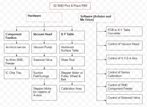
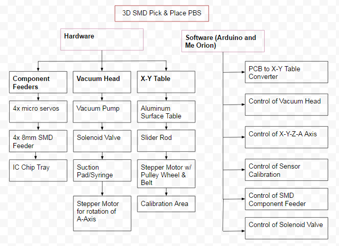
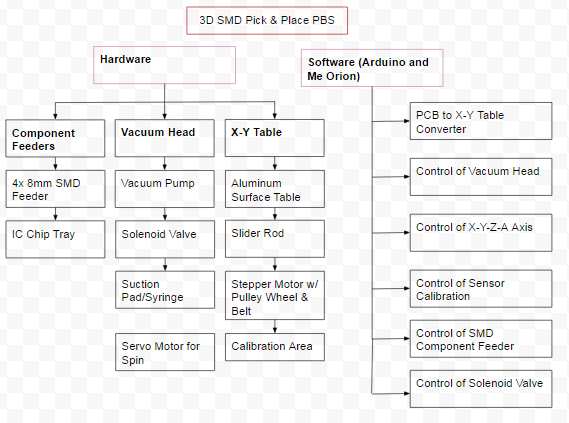
Figure 1. Product Breakdown Structure

The Product Breakdown Structure (PBS) shows all the functional blocks of our pick and place 3D SMD machine. The hardware is split into three different categories: Component Feeders, Vacuum Head, and X-Y Table. We will need a minimum of 4x micro servos to control our 4x 8mm reel feeders and an IC chip tray. The Vacuum head will consist of a vacuum to suction the components, a syringe or vacuum pen to pick up our components, a solenoid valve to block airflow and allow our components to be placed, and finally a stepper motor for rotation of the A axis. The X-Y Table is purchased from MakeBlock; however, we will need an aluminum surface table, slider rods, stepper motors, and calibration sensors to orientate our components. For software, we plan on using Arduino to program the Arduino Uno and Me Orion microcontrollers. Software must be able to convert Gerber files into G-code which can be read by our Me Orion microcontroller. We will need to be able to control all axis of our machine, the calibration sensor, component feeders, and solenoid valve through software.

Software Design

by Christine Vu (Systems Engineer)

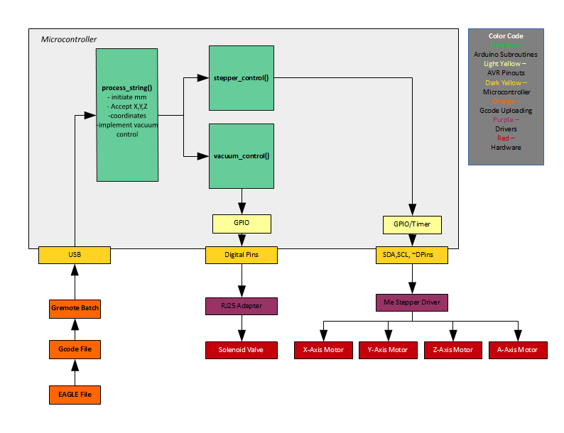
The Makeblock X-Y Plotter Robot Kit software begins with the submission of a gcode file. An EAGLE file is submitted and converted to gcode for the Arduino sketch to translate. There are three main subroutines to process the gcode coordinates–process_string, stepper_control, and vacuum_control. In process_string, the code searches for x-coordinates, y-coordinates, and z-coordinates. In the stepper_control, x-,y-, and z-coordinates, are processed to move the motors. The vacuum_control is used to detect when the vacuum tubing should open and close according to the change in the z-coordinates.

Preliminary Software Design

Figure 2. Software Design


Electronic System Design

Source Material

Me Orion:

Me Stepper Driver:

System Block Diagram

By Christine Vu (Systems Engineer) and Henry Nguyen (Electronics Engineer)

Screen Shot 2016-03-05 at 7.33.48 PM Screen Shot 2016-03-05 at 7.34.24 PM Screen Shot 2016-03-05 at 7.34.33 PM

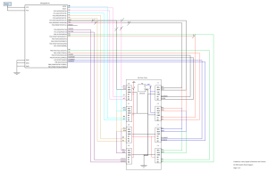
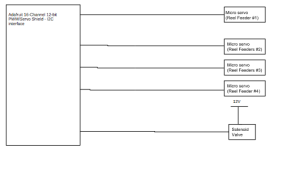
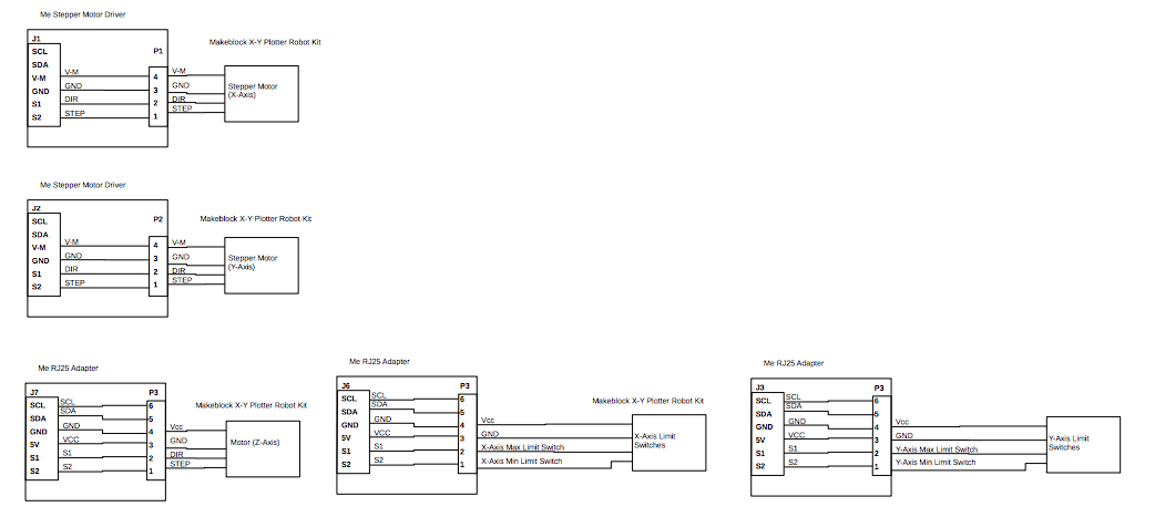
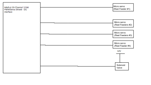
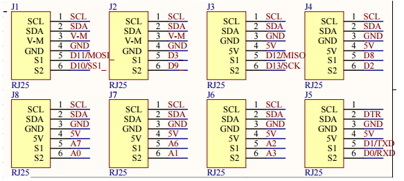
Figure 3. System Block Diagram

The images above is the system block diagram for our pick and place 3D SMD Machine. We are currently using a Me Orion microcontroller provided by Makeblock. This microcontroller has an Atmega3280-AU microprocessor, 8 Me RJ25 ports, two Me Stepper drivers, and 3 Me RJ25 adaptors. The pin outs for each Me RJ25 port is shown above which is connected to our microprocessor. Every port on our Me RJ25 has a SDA and SCL which is our I2C. This will be all connected to our PC4 and PC5 respectively. We will be using ports J1, J2, J3, J6 and J7. The first two ports is to control our X and Y axis stepper motors. J6 and J3 is to control our X and Y axis limit switches respectively. Finally J7 is to control our Z-axis micro servo. We plan on having another micro servo to serve as our A-axis component orientation which may connect to any other available ports. Next we are considering a Adafruit 16-Channel I2C interface in order to connect all of our micro servos for our reel feeders. We currently will need 4 servos for this purpose; however, for future semesters, they may need to implement more reel feeders. Our vacuum will be constantly running on a separate power source. The solenoid valve will close off the vacuum to prevent suction. This will allow our components to be placed onto our PCB after our machine picks it up.

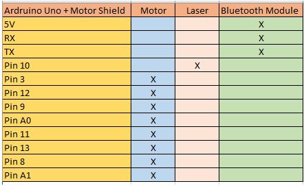
Interface Definition

Interface Matrix

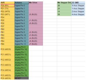
Figure 4. Interface Matrix

The image above is the interface matrix for our pick and place 3D SMD machine. We will be utilizing an Arduino Uno, Me Orion, and Me Stepper Driver. Me Orion and the Me Stepper Driver came with our X-Y Plotter. This Me Orion is based off of an Arduino Uno, which will allow us to code using Arduino, Scratch. and AduBlock. We will be using this microcontroller because it has 8 RJ25 ports which will be useful for all of our actuators. The Me Stepper Driver will be used to precisely control our stepper motors by operating our motors in full, half, quarter, eighth, and sixteenth step modes. This modes can be easily changed using the built-in DIP Switch. We will need 4 Me Stepper Drivers in order to control all of our stepper motors on each axis (x,y,z,A).

Me Orion Schematic

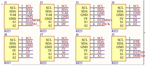
Figure 5. Me Orion Schematic

Me Stepper Driver Schematic

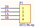
Figure 6. Me Stepper Driver Schematic

Specification for  Me Orion:

Operating Voltage: 6-12V DC power;

Microcontroller: ATmega238;

Detecting Angle: prefer at 30 degree angle;

Dimension: 80 x 60 x 18 mm (Length x Width x Height);

Specification for Me Stepper Driver:

  • Max current: ±1.35A
  • Max motor drive voltage: 25V    
  • Note: Me BaseBoard max supply  voltage 12V
  • Logic voltage: 5V
  • Dimensions: 48mm*24mm(Length × Width)

Mechanical Design

By Nasser Alsharafi (Manufacturing)

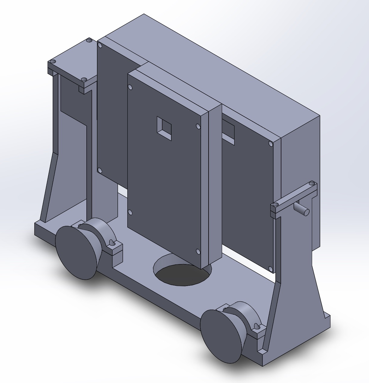
In this part of the project for the XY plotter I am coming up with the design of a Reel Feeder. The main purpose of a reel feeder is to feed the machine with the surface mounted parts. The reel feeder is made of aluminum. The main function of the Reel Feeder wheel is to roll and pass on the parts to the Reel Feeder base, which then the parts will be picked up by the vacuum.

FeederReelAssembly

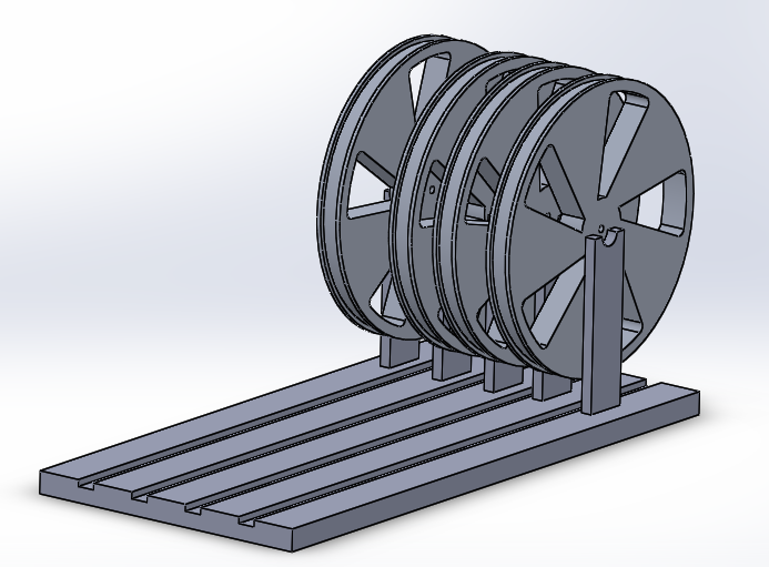
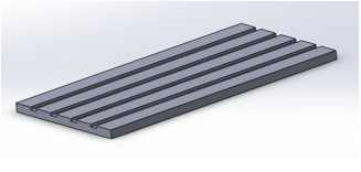
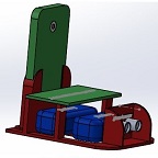
Figure 7. Complete reel feeder assembly 3D model

Reel Feeder Base

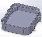
Figure 8. Reel feeder base

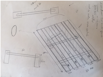
The base sheet of the reel feeder has four channels called the grooves in which the tape passes through. The base sheet of the reel feeder has a length of 270 mm and a width of 82 mm. Each of the grooves on the base sheet of the reel feeder has a width of 8 mm. The main function of the reel feeder is to guide the tape to the part of the feeder where the chip is first pulled and then picked by a vacuum pen. This action helps in preparation of the next chip. After, the chip is taken by the vacuum pen and is placed on the PBC board.

Reel Feeder Wheel

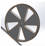
Figure 9. Reel feeder wheel

Initial Sketch of Reel Feeder Base

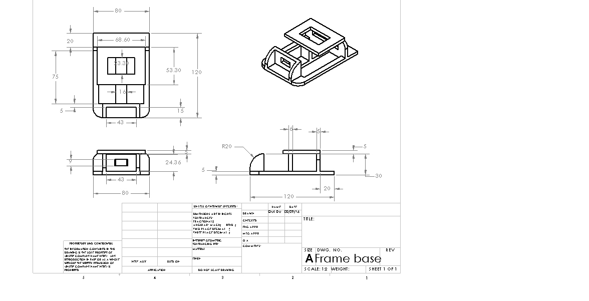
Figure 10. Drawing of initial reel feeder base

Currently, our reel feeder is manual, so there can be further improvements by making the reel feeder automatic. In order to make the reel feeder automatic, I have to design a mounting bracket for 4 micro-servos. Each channel has single micro-servo to pull back the tape while pushing the reel forward. This will be implemented by working with Henry Nguyen to control the micro-servos.   

Design and Unique Tasks

Design

by Nasser Alsharafi (Manufacturing)

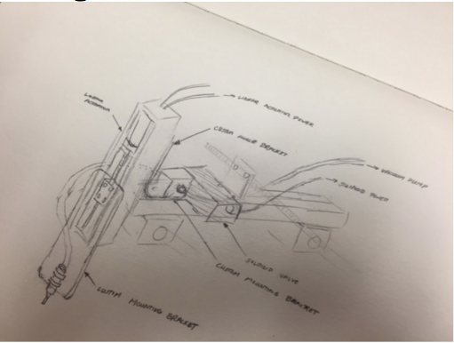
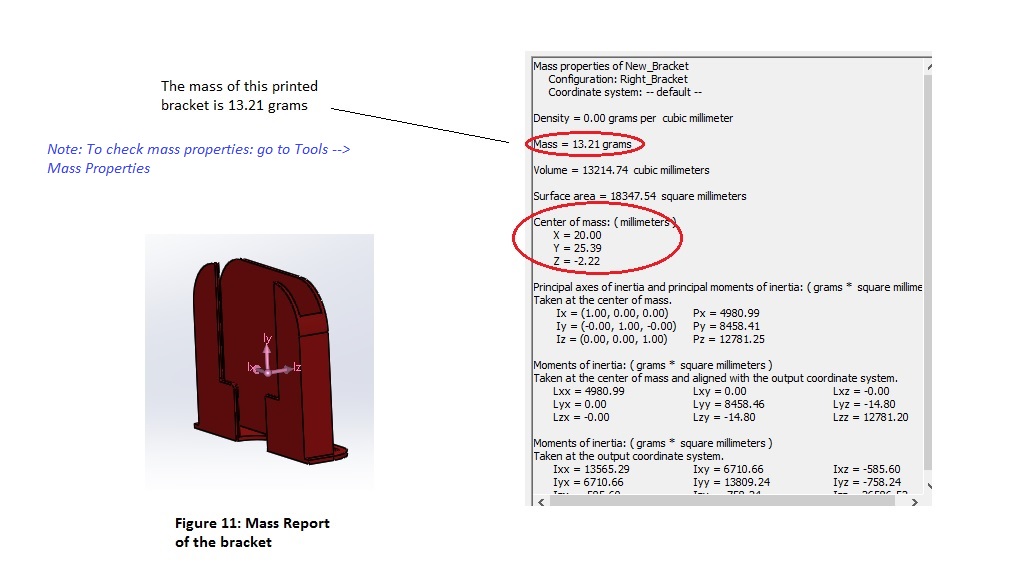
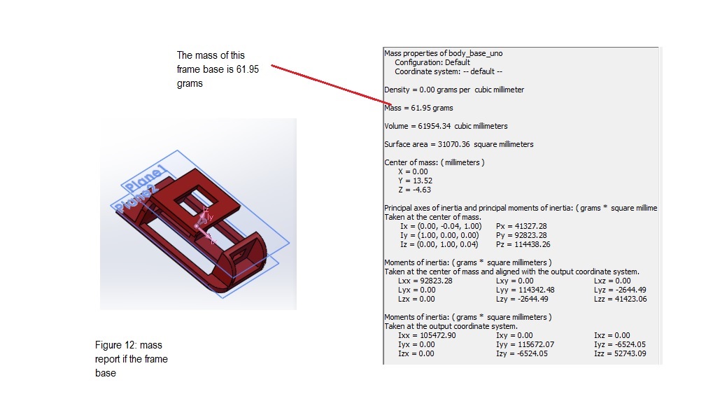
The pick and place vacuum nozzle system was sketched out. We had to take into consideration the weight of the entire system and make sure our actuator can support that weight.

Screen Shot 2016-03-05 at 7.14.25 PM

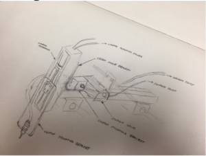
Figure 11. Actuator Design

Unique Tasks

By Bao Loc Doan (Project Manager), Henry Nguyen (Electronics Engineer), Christine Vu (Systems Engineer)

The stepper motor movement for the X and Y axis were mirrored. If we wanted the XY plotter to move left, it would move right. If we wanted the XY plotter to move up, it would move down. The solution was to change the connection of the wires to the opposite orientation. There are 4 wires that are output from the stepper motor. The wire colors are green, blue, red, and black. Rather than inputting it as green,blue,red,black into the connector, we switched the orientation to black, red, blue, and green. This changed the stepper motor orientation.

The limit switches also were not working correctly. When the XY plotter was supposed to stop due to it reaching the limits of its working area, the XY plotter kept going and ramming into the edges of the XY plotter. The manual for the XY plotter had the limit switches going from an RJ25 into port 5 of the Arduino. This was wrong. After hours of debugging and testing software, we realized this error. The limit switches ended up working after plugging it into port 7 of the Arduino.

Project Status

by Bao Loc Doan (Project Manager), Christine Vu (Systems Engineer), and Henry Nguyen (Electronics Engineer)

Currently, we were able to successfully translate an EAGLE PCB file to G-CODE. There are two layers, TORIGINS and TPLACE, specifically from EAGLE PCB that were used. TORIGINS displays the centerpoint of each component and TPLACE displays the outline of the component so the system could possibly recognize which orientation the component should be placed. The issue that we are currently facing is interpreting all the G-CODE location sets and translating it in a way for our XY plotter to properly read them.

Screen Shot 2016-03-05 at 6.27.23 PM

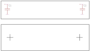
Figure 12. Torigins and Tplace layers

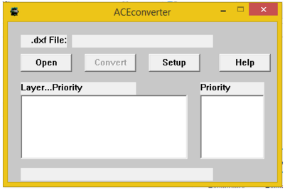
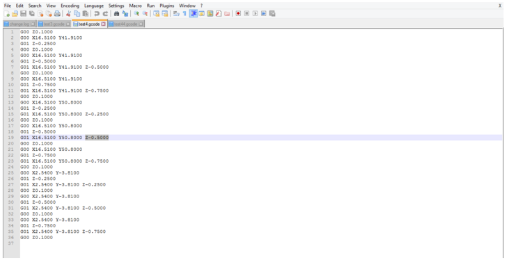
In order to successfully translate EAGLE to GCODE, the EAGLE file needs to be exported into a .DXF file. Then we can use ACEconverter to translate the .DXF file to GCODE. Using Notepad++, then the Z-axis can be modified to our needs.

Screen Shot 2016-03-05 at 6.27.33 PMScreen Shot 2016-03-05 at 6.27.43 PM

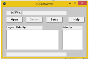
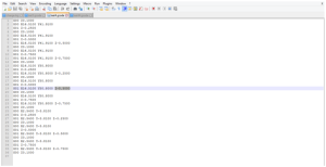
Figure 13. ACEconverter and Notepad++

A trade-off study on the vacuum system was conducted as well. We are currently deciding which aquarium pump to use, whether it is 20 gal, 40 gal, or 100 gal. There are still experiments that need to be conducted and we will provide updates when those experiments are done. The trade-off study blog was created and can be seen here.

A separate blog has already been made for the XY plotter that was purchased and that blog will explain all design ideas as well as provide updates on how the XY plotter functions. The blog can be seen here.

Work Breakdown Structure

By Bao Loc Doan (Project Manager) and Christine Vu (Systems Engineer)

Our Work Breakdown Structure (WBS) was modeled after the Robot Project WBS. Each division will have tasks delegated to them and will be their primary responsibility to complete. As mentioned in 05 Preliminary Project Plan PDF, the WBS will be a “…  hierarchical tree structure where each node (group) is the responsibility of only one engineer.”  A completion of the WBS will indicate a successful project. The chart below will be the pick and place SMD machine WBS.

WBS

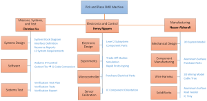
Figure 14. Work Breakdown Structure

Source Material

[1] G.Hill (2016, Feb). 05 Preliminary Project Plan [Online]. Available: 05 Preliminary Project Plan PDF

Project Schedule

A project schedule will lay out the deadlines that each engineer needs to conform to when assigned to their tasks. The schedule will allow the engineer to understand how much time they have left as well as the progression needed to complete the project. When deadlines are not met, there will be a chart illustrating the remaining cumulative work as well as baseline cumulative work.

Top Level Schedule

By Bao Loc Doan (Project Manager) and Christine Vu (Systems Engineer)

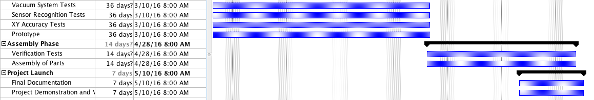
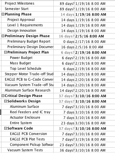
The top level schedule tasks were derived from our WBS. Each module in the WBS were taken into account. While working with the systems engineer, we developed a schedule that will divide all tasks in a progression that we believe will lead to project completion. Each required task will have a time estimate, and failure to meet the time estimated will result in the delay of every task assigned after. The chart below is the pick and place SMD top level schedule.

Screen Shot 2016-03-03 at 9.47.22 PM

Screen Shot 2016-03-03 at 9.47.56 PM

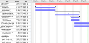
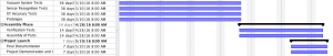
Figure 15. Top Level Schedule

System/Subsystem Level Tasks

By Henry Nguyen (Electronics Engineer), Christine Vu (Systems Engineer), and Nasser Alsharafi (Manufacturing)

Reference top level schedule for system/subsystem level tasks.

Burn Down and Project Percent Completion

by Bao Loc Doan (Project Manager)

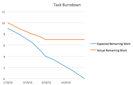
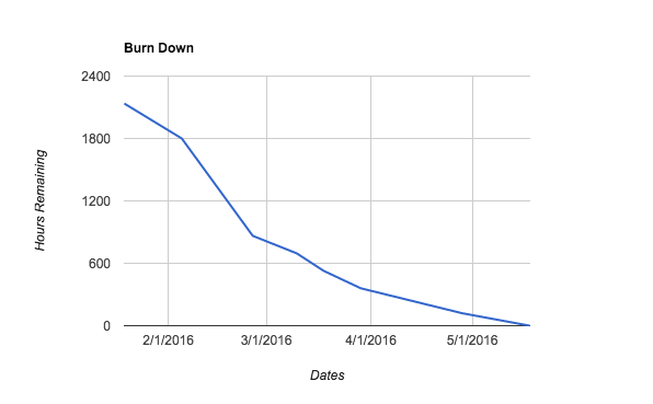
A burn down graph is a visual representation of the expected progression and remaining progression. The top level schedule was created in ProjectLibre, so we had to use Excel to create a burn down graph. The task burn down and the percent burn down will be shown below.

 Screen Shot 2016-02-26 at 10.03.38 AM Screen Shot 2016-02-26 at 10.04.30 AM

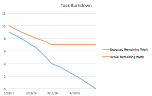
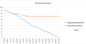
Figure 16. Burn Down Graphs

System Resource Reports

Mass Report

By Christine Vu (Systems Engineer)

Vacuum System Components Preliminary Mass (g) Uncertainty (%) Margin (±g) Expected Mass (g) Actual Mass (g)
Stepper Motor (A-Axis) 290.00 5% 14.5 304.50
Stepper Motor (Z-Axis) 290.00 5% 14.5 304.50
Solenoid Valve 99.79 5% 4.99 104.78
Makeblock Stepper Driver (2 ct.) 40.00 5% 2 42.00
Vacuum Syringe 68.00 5% 3.4 71.40
Vacuum Tubing (25-ft.) 68.00 5% 3.4 71.40
Project Allocation Trade-Off Study will be obtained
Total Expected Mass 898.58
Total Margin 42.7895
Total Actual Mass
Contingency

Table 1. Mass Report

Summary

The pick and place SMD machine will not need a power resource report because we are not limited in power. A waiver request will be submitted for approval.

The mass resource report is on the vacuum system to determine the mass. The stepper motor expected weight have been obtained from the Makeblock specifications on their X-Y Plotter Robot Kit (Shenzhen Maker Works Technology Co., Ltd., 2013).

The Makeblock Stepper Motor Driver is a component used to control the stepper motor with  the ArduinoUno. It contains a stepper driver chip, 4 wire bi-polar stepper motors, a potentiometer, DIP switch, and a heat sink.

Because the components have not been purchased, project allocation, actual mass, and contingency will be obtained after trade-off studies have been conducted.

Source Material:

Shenzhen Maker Works Technology Co., Ltd. (2013). Me Stepper Motor Driver. Retrieved from:http://www.makeblock.cc/me-stepper-motor-driver/

Project Cost Estimate

By Bao Loc Doan (Project Manager) and Christine Vu (Systems Engineer)

Resource Unit Price ($) Quantity Shipping Cost ($) Preliminary Cost ($) Uncertainty (%) Margin (±$) Expected Cost ($) Actual Cost ($)
MakeBlock XY Plotter Robot Kit $267.66 1 $0.00 $267.66 8.00% $21.41 $289.07 $267.66
Tetra Aquarium Pump $17.59 1 $0.00 $17.59 8.00% $1.41 $19.00
8 mm Reel Feeders (Holds 4) $32.00 1 $0.00 $32.00 8.00% $2.56 $34.56
Micro Servo $7.00 4 $0.00 $28.00 8.00% $2.24 $30.24
12V Solenoid Valve $10.00 1 $0.00 $10.00 8.00% $0.80 $10.80
Aluminum Surface & Machinist Labor $60.00 1 $0.00 $60.00 8.00% $4.80 $64.80
42BYG Geared Stepper Motor $60.00 2 $0.00 $120.00 8.00% $9.60 $129.60
Vacuum Tubing (25-ft) $5.00 1 $0.00 $5.00 8.00% $0.40 $5.40
MakeBlock Stepper Driver $18.00 1 $0.00 $18.00 8.00% $1.44 $19.44
Sensor Calibration $50.00 1 $0.00 $50.00 8.00% $4.00 $54.00
Connectors $2.00 2 $0.00 $4.00 8.00% $0.32 $4.32
$0.00 $0.00 8.00% $0.00 $0.00
Project Allocation $650.00
Total Expected Cost $612.25
Total Margin $48.98
Total Actual Cost $267.66
Contingency $86.73

Table 2. Cost Report

Summary

The cost report supports all parts needed so far to construct the pick and place SMD machine for Spring 2016.

The Makeblock XY Plotter is an XY plotter that can be easily modified to our needs. This specific XY plotter has a working area of 12” x 15” so it can easily fit our PCB fabrication requirements (4” x 3.2” as per free Eagle CAD board working area) and additional reel feeders. The Makeblock XY plotter ships all the parts as a kit and would be much more efficient to build since we would no longer need to design the entire XY plotter. The accuracy of this XY plotter needs to be increased by a factor of 2 (as requested by the customer) and a simple solution is to implement a geared stepper motor.

The Makeblock Gearbox Stepper Motor will be implemented into our pick and place SMD machine so our precision error meets customer standards of 0.002”.

The aquarium pump, solenoid valve, tubing, syringe, and connectors shall be used for the vacuum system in the pick and place SMD machine. The aquarium pump is easily modified to become a vacuum and the solenoid valve with brass fittings will control when the vacuum suctions in order to pick and up and place down the components as intended. The tubing, syringe, and connectors will connect each individual component to make the vacuum system.

All of our surface mount resistors and capacitors shall be placed in the 4x 8 mm reel feeders so they can be populated onto the PCB. After Spring 2016, 16x 8 mm reel feeders will be implemented into the pick and place SMD machine.

The aluminum surface will be the working area of the entire pick and place SMD machine. The machinist labor is included into the price. The Makeblock XY plotter will need to securely fit into the aluminum surface and there will also be an aluminum clamping system that needs to be drilled into the aluminum surface.

The Makeblock stepper motor driver will be used in conjunction with the Makeblock stepper motor to control our vacuum nozzle. In order for the vacuum to be able to pick up components, the ability to move in the Z-axis is required. We have plans to implement one Makeblock stepper motor on the z-axis and will need the circuitry required.

Spring 2016: 3DoT Spider-Bot IR Transmitter and Receiver Research

By: Christopher Hirunthanakorn (Missions, Systems and Test Engineer)

PIR diagram

Introduction:

In order to determine which optical transmitter and detector would be the best solution for implementing the game of tag between the 3DoT David and 3DoT Goliath,, the following research on IR transmitters and detectors was done. It started with learning about the various types of transmitter and detector systems that are available such as pre-made transmitters and passive infrared sensors (PIR sensor). From there, specific characteristics were researched such as range, sensitivity, power consumption, and size. Afterwards, the pros and cons of using a basic IR transmitter and detector are listed to be used for discussion.

Related Requirement:

Because this research was done before the type of tagging system to be used was decided on by both teams, this is the most relevant requirement.

  • The 3DoT David shall use an infrared LED emitter and infrared detector for the tagging system in the game of tag.

Types of IR systems:

The various types of transmitter and detector systems can be broken down into three major groups, which are the basic systems, data transmission systems, and the motion detection systems. The basic systems are composed of just an infrared emitter and an infrared detector. The emitter is typically an IR LED that emits light in the 850 nm to 950 nm range(1). The detector is usually a photosensitive transistor that conducts current when IR light is detected. Data transmission systems are the IR transmitters and receivers that are typically found in remote controls. They are used to send data and are more expensive than the basic systems because they are pre-made circuit boards. They have better range and sensitivity than the basic systems(2). Unfortunately, they are not suited for the game of tag because those features are beyond the scope of the project. The final type of IR transmitter and detector systems are the PIR sensors. They are typically used in motion detection applications and passively detect changes in reflected IR waves(3). The PIR sensor would have been the most promising solution except for the issue with false positive results when the robot moves or turns. Once this was done, more detailed research was performed on the basic system of IR transmitters and detectors.

After additional research, more information on the range, sensitivity, and ways to improve those characteristics was found. The normal range of the IR transmitter is two to four feet when it is supplied with the rated current. It is possible to improve the range of the transmitter by amplifying the current above the rated value as mentioned in several forum posts(4). It requires building a small circuit with a transistor to provide the necessary current. As for the sensitivity of the IR detector, some types have a large viewing angle. This means that the detector has a wide field of vision for detecting any infrared light. The large viewing angle could cause issues for the game of tag since it is possible for the detector to trigger when the transmitter of the other robot is not pointed in the right direction to hit the detector. After searching the internet, two possible solutions to issue were found. One solution involves picking an IR transmitter with a narrow viewing angle and utilizing a collimator to decrease the spread of the infrared light(5). It will make sure the infrared light is directed in the desired direction and improves the range of the transmitter(6). The other solution is to create an enclosure around the detector so that it will narrow down the viewing angle and modify the sensitivity to the level that suits the game of tag.
IR range pic

Conclusion:

When considering the use of an IR transmitter and detector for the tagging system, the best solution was the IR emitter and detector combination. Our robot needed the sensitivity and controllable intensity that this combination provides because the range of the tagging system must be customizable. The other IR systems did not provide this amount of control and were eliminated. We are currently considering the solution that involves using a lens to focus the intensity of the IR emitter.

Work cited:

  1. http://www.futureelectronics.com/en/optoelectronics/infrared-emitters.aspx
  2. http://www.seeedstudio.com/wiki/Grove_-_Infrared_Emitter
  3. https://learn.adafruit.com/pir-passive-infrared-proximity-motion-sensor/how-pirs-work
  4. http://www.instructables.com/answers/How-to-get-the-best-range-out-of-an-IR-LED/
  5. http://electronics.stackexchange.com/questions/170993/can-an-ir-transmitter-be-focused
  6. http://forum.arduino.cc/index.php?topic=157622.0

Spring 2016 RoFi: Mechanical Design Rev.1

Christopher Andelin (Project Manager)

Mario Ramirez (Systems Engineer)

Qui Du (Manufacturing Engineer)

Andrew Laqui (Electronics and Controls Engineer)

Henry Ruff (Electronics and Controls Engineer)

Table of Contents

Mechanical Design

Qui Du (Manufacturing Engineer)

Objectives for this Design

RoFi is the fifth prototype from Project Biped. It has twelve degrees of freedom and can walk around while avoiding obstacles using an ultrasonic range sensor. A small Android phone in RoFi’s head provides the brains, an Arduino Uno provides the hardware interface, and batteries to power the servos. By reading the “RoFi- Next Generation Head- DAREL” project designed by Mike Pluma, I think this is a good design for our Rofi; therefore, I used this design for our RoFi head.

Body base design planning

figure 1


Sources:

http://web.csulb.edu/~hill/ee400d/Project%20Folder/Robots%20and%20Drones/BiPed%20Robot/RoFi%20Project/

https://www.adafruit.com/datasheets/arduino_hole_dimensions.pdf

http://www.hobbyking.com/hobbyking/store/__9493__Turnigy_1300mAh_3S_30C_Lipo_Pack.html

http://www.seeedstudio.com/wiki/index.php?title=Ultra_Sonic_range_measurement_module

SolidWorks Modeling Design

Step 1: determine dimensions of the body base

Long dimension of  body base ≥ width dimension of phone base + (2*width dimention of battery) + width dimension of ultrasonic sensor +dimensions of two walls.

Long dimension of body base ≥ 20 + (2*34) + 15 + 10 = 109; however, we need space for wires and extra items, the long dimension of body base is 114 mm.

Width of body base ≥ long dimension of battery = 78, since the long dimension of a battery  has a largest scale to be place in the body base; therefore I round width dimension of body base to 80 mm.

Step 2: SolidWorks model for body base

figure2

figure 3

Note: plane2 was added to make an extend space (5mm)  for the phone bracket.

Drawing diagram

Frame base2


Step 3: SolidWorks Prototype of batteries

For our projects,  the battery type is the last item to be chosen, however, to make my body base design more realistic, I chose the battery type from last semester as an prototype of this design.

Battery Turnigy 1300Ah 3S 30C. Dimensions: 78 x 34 x 23mm

Source: http://www.hobbyking.com/hobbyking/store/__9493__Turnigy_1300mAh_3S_30C_Lipo_Pack.html

figure4

Step 4: SolidWorks prototype for Arduino Mega

Arduino Uno has dimensions: 68.6 x 53.3 x 2mm

Source: https://www.adafruit.com/datasheets/arduino_hole_dimensions.pdf

figure 5


Step 5: SolidWorks prototype for Ultrasonic Sensor

figure 6

Step 6: Make a new prototype bracket for Android phone

In the last blog post (https://www.arxterra.com/spring-2016-rofi-preliminary-design-documentation/), I designed brackets that support a phone in either vertical or horizontal orientations; therefore, I made a bracket from 2 pieces that can be adjustable to fit with width dimension of the phone. Because my project just needs the phone to be placed in the vertical orientation; therefore, in this new design, I make a one piece bracket for the android phone.

figure7

Drawing diagram

New_Bracket_drawing

Step 7: Make a prototype of an Android phone

figure8

Step 8: Assembly Modeling and Exploded View

figure9


Mass Reports


By using the Mass Properties feature, I can determine the mass of the designs before they are printed.

figure11

figure 12

Spring 2016 RoFi: Ultrasonic Sensor Testing

Christopher Andelin (Project Manager)

Mario Ramirez (Systems Engineer)

Qui Du (Manufacturing Engineer)

Andrew Laqui (Electronics and Controls Engineer)

Henry Ruff (Electronics and Controls Engineer)

Testing Ultrasonic Sensor

Andrew Laqui (Electronics and Controls Engineer)

The Ultrasonic Sensor that was on the old RoFia project was the model SEN136B5B. Their testing can be found on this link here, https://www.arxterra.com/ultrasonic-sensor-testing/. Although the RoFia group seemed to have done some quick calculations regarding how far Rofia can detect obstacles, the method of determining these distances are unclear.


For testing, the code found at https://www.arduino.cc/en/Tutorial/Ping was used to test how the sensor worked. Initially, the sensor was not seeming to detect anything, but after double checking the wiring, it was determined that the Fritzing diagram found on the Arduino site had a different wiring than the SEN136B5B sensor. Once the wiring was connected properly, the Arduino serial communication began to immediately print onto the screen. The test code printed the distance that the sensor was detecting, which made it possible to determine what angles the sensor could accurately detect.


A folder was used to simulate a tall object for the SEN136B5B to detect. The folder was held on the side to determine the widest angle the sensor can detect. The sensor was then placed on a tall object in order to determine the vertical detection angles.


The table below has the measurements listed.

table