Project Preliminary Design Spring 2016 Millennium Falcon

By: Luis Valdivia (Project Manager)

Kevin Nguyen (Electronics and Control)

Juan Mendez (Manufacturing and Design)

Anthony Becerril (Mission, System, and Test)
Work Breakdown Structure

Capture


The Work Breakdown Structure (WBS) above outlines all the necessary work for the Millennium Falcon to succeed in meeting requirements. Each division has their own systems and subsystem tasks that must be done for project completion.


Project Schedule


  • Top Level Schedule


pLibre1

pLibre2

The top level schedule aligns with the WBS and outlines tasks to be done by each division as well as overall team tasks.


  • System/Subsystem Level Tasks


Division Task Details Completion Date
Mission, Systems, and Test LED Lightshow Programming Complete programming for customizable LED lightshow 3/10/2016
Arduino/ Programming Complete programming for arduino board to communication with quadcopter 4/4/2016
Android/iOS Application Successfully complete phone application compatible with Arxterra 4/4/2016
Verification Testing Create testing procedures, complete testing, and report results 5/3/2016
Electronics and Control New PCB Design revise previous design to be all on one board 3/4/2016
Battery Discharge Test create and complete battery discharge test 3/25/2016
Voltage Monitoring Test create and complete voltage monitoring test 3/28/2016
PID Tuning create successful PID tuning system 4/20/2016
Communication Verification Setup and verify communication with RC and bluetooth 4/27/2016
Manufacturing and Design 3D Model Create complete 3D model with parts 5/5/2016
PCB Stencil PCB printed and finalized by implement components 3/31/2016
Shell Mold Create quadcopter shell mold 4/29/2016
Shell Latching Implement latching system of shell to rest of quadcopter 4/29/2016
Component Assembly Complete assembly of quadcopter 5/2/2016
Parts Ordering Fully order all parts necessary for project
EDF Attachments Successfully create and attached various EDF attachments
  • Burn Down schedule

Burn down schedule chart display the total work remaining throughout the semester. As we progress, the percentage of work remaining will decrease.

Burndown

System Resource Reports

pOWER

mASS

Cost

Project Cost Estimate

The cost estimate comes from the cost report done within system resource reports and is inexpensive. Most of our cost going to renewing existing parts and adding modifying parts (e.g. servos). The costs are as follows:

Projection Allocation: $150.00

Total Margin:            $33.40

Total Expected Cost: $167.00

Contingency: $16.40

Spring 2016 3D SMD: Vacuum System Trade-Off Study

By Henry Nguyen ( Electronics and Control)

DISCLAIMER: We have not purchase our vacuum pump; however, we spoke to President Watts and he would like to see the procedure for this trade off study. This blog will be updated when we obtain our materials and perform our tests.

Introduction

In order to find a vacuum pump that best suits our pick and place SMD machine, we needed to compare several different options. Considering pressure and cost will be crucial for this trade off study. Our goal is to find a vacuum pump that is able to pick up surface mount components and IC chips. We found that we can modify a 60 -100 gallon Tetra Whisper Aquarium pump to act as a vacuum for the price of $17.59.

—Equipment and Materials

Syringe 5mL                      Needles-min

Figure 1. 5 mL Syringe                                                          Figure 2. Needle heads

  1. A 5mL syringe with a small needle with a diameter of less than 0.50mm

ICs-min

Figure 3. Various surface mount components and IC Chips

      2. Various surface mount components and IC Chips

Tetra 100 Gal-min

Figure 4. Tetra Aquarium Pump

      3. Vacuum pump (Modified aquarium pump) 

Tubing-min

Figure 5. Tubing

      4. 3/16” tubing

—Procedure

  1. We will modifying the following aquarium pump in order to turn it into a vacuum pump. The following link provides step-by-step details on how to modify our aquarium pump
    1. http://www.instructables.com/id/Circuit-Board-Lab-POV-Business-Card/step5/
  2. Tubing length will be cut to be as short as possible to allow maximum suction pressure. The size will be determined based on the design of our aluminum surface table. (Approximately 1.5 – 3 ft)
  3. A 5mL syringe will be used as our vacuum head and will be modified by connecting our tubing to the syringe and our vacuum
  4. After setting up our equipment, we will be testing whether or not our vacuum is able to pick up a 402 component.
  5. Next we will be testing the heaviest IC chip that we have access to in order to determine if our small needle is able to pick up the IC Chip.
  6. Our last step is to test how much mass our vacuum pump is able to pick up. In order to do so, we will have a small scale with an accuracy of 0.1 grams and we will place an object on that scale. We will use our vacuum to see how much grams is deducted of the total mass when attempting to pick up the object. The following video shows a demonstration of this process.
    1. http://www.exair.com/pages/theater.aspx?gi=13001&dlg=1&gf=Vacuum+Generators

—Results

  • Currently unavailable until we purchase our equipment

—Analysis/Discussion

  • Currently unavailable until we purchase our equipment

—Conclusions/Implications

  • Currently unavailable until we purchase our equipment

—References

Vacuum Pump modifcation and image:

Sponges, S. (n.d.). Build an SMD Vacuum Pick and Place Tool. Retrieved February 25, 2016, from http://www.instructables.com/id/Circuit-Board-Lab-POV-Business-Card/step5/

Vacuum Pump mass test:

EXAIR: Manufacturing compressed air products since 1983. (n.d.). Retrieved February 25, 2016, from http://www.exair.com/pages/theater.aspx?gi=13001

ICs Image:

Curious Inventor. (n.d.) Hand full of SMDs Labeled. Retrieved February 25, 2016, from

http://store.curiousinventor.com/media/smt/hand_full_of_smds_labeled.jpg

Tetra Whisper Aquarium Pump Image:

Tetra Whisper Air Pump (Non-UL). (n.d.). Retrieved February 26, 2016, from http://www.amazon.com/Tetra-77851-Whisper-Pump-10-Gallon/dp/B0009YJ4N6/ref=sr_1_1?s=pet-supplies

3/16” Tubing Image:

Python. (n.d.). Retrieved February 26, 2016, from http://www.amazon.com/Python-Airline-Tubing-Aquarium-25-Feet/dp/B000255NYQ/ref=pd_bia_nav_t_1?ie=UTF8

Spring 2016 Pathfinder Preliminary Project Plan

WBS

By:

Peiyuan Xu                        (Project Manager)

Xiong Lee                          (Mission, System and Test Engineer)

Table of Contents

Work Breakdown Structure

by:

Peiyuan Xu                         (Project Manager)

WBS

This work breakdown structure demonstrate all the work needed to be done for this project Pathfinder Rover. There are four branches that indicates different job duties and division works assigned to the system and subsystem engineers.

Project Schedule

Top Level Schedule

schedule1schedule2schedule3schedule4

The charts above shows the preliminary project schedule and tasks that assigned to team members. Each task has a start date and end date indicated the period of the task.

Burn Down and Project Percent CompletionBurn Down

project overview


The Burn Down graph shows the overall project progress and remaining time to complete the project.

The Project Overview graph shows the project percent completion directly from calculation.

System Resource Report

by:

Xiong Lee                                   (Mission, System and Test)

Mass Report

mass report

Our mass is capped to 10 pounds or 4535.92 grams. Looking through the report, we have a contingency of 2519.56 grams. Our total expected mass should be a little over half the mass capacity of the rover. Most of the materials we are using are ABS plastic which is 3D printing. These materials are very light and will help us achieve the goal of staying under 4535.92 grams.

Power Report

power report

The Power budget is how much current our electronics draw. This report is from the specification sheets only. We have not measured the current these electronics draw. Our goal is to use this report to choose a battery that can give us 4 hours of run time. We will have to limit what we put into our design. The motors are the hardware that draws the most current.

Project Cost Estimate

Cost report

Our budget that we have is 500 dollars. We are reusing some of the parts that were on the previous pathfinder. Most of the parts we are reusing are the electronic parts. We need to figure out how many battery we need to run for 4 hours. We added two batteries onto the cost budget. We have a contingency of $225.12 dollars. With a margin of 82 dollars, we have $143.12 left under the budget.

 Source Materials

http://www.amazon.com/Baitaihem-Arduino-Wireless-Bluetooth-Receiver/dp/B00J1D6UBA


https://www.pololu.com/product/2507/specs

https://www.adafruit.com/products/191

http://www.gearbest.com/development-boards/pp_43066.html

http://www.tenergy.com/31016

https://www.sparkfun.com/products/13784


Spring 2016 3D SMD: Preliminary Project Plan

by Bao Loc Doan (Project Manager)

Christine Vu (Systems Engineer)

Henry Nguyen (Electronics Engineer)

Nasser Alsharafi (Manufacturing)


Table of Contents

Work Breakdown Structure

By Bao Loc Doan (Project Manager) and Christine Vu (Systems Engineer)

Our Work Breakdown Structure (WBS) was modeled after the Robot Project WBS. Each division will have tasks delegated to them and will be their primary responsibility to complete. As mentioned in 05 Preliminary Project Plan PDF, the WBS will be a “…  hierarchical tree structure where each node (group) is the responsibility of only one engineer.”  A completion of the WBS will indicate a successful project. The chart below will be the pick and place SMD machine WBS.

WBS

Figure 1. Work Breakdown Structure

Source Material

[1] G.Hill (2016, Feb). 05 Preliminary Project Plan [Online]. Available: 05 Preliminary Project Plan PDF

Project Schedule

A project schedule will lay out the deadlines that each engineer needs to conform to when assigned to their tasks. The schedule will allow the engineer to understand how much time they have left as well as the progression needed to complete the project. When deadlines are not met, there will be a chart illustrating the remaining cumulative work as well as baseline cumulative work.

Top Level Schedule

By Bao Loc Doan (Project Manager) and Christine Vu (Systems Engineer)

The top level schedule tasks were derived from our WBS. Each module in the WBS were taken into account. While working with the systems engineer, we developed a schedule that will divide all tasks in a progression that we believe will lead to project completion. Each required task will have a time estimate, and failure to meet the time estimated will result in the delay of every task assigned after. The chart below is the pick and place SMD top level schedule.

Top level schedule 1

Top level schedule 2

Figure 2. Top Level Schedule

System/Subsystem Level Tasks

By Bao Loc Doan (Project Manager), Henry Nguyen (Electronics Engineer), Christine Vu (Systems Engineer), and Nasser Alsharafi (Manufacturing)

Reference top level schedule for system/subsystem level tasks.

Burn Down and Project Percent Completion

by Bao Loc Doan (Project Manager)

A burn down graph is a visual representation of the expected progression and remaining progression. The top level schedule was created in ProjectLibre, so we had to use Excel to create a burn down graph. The task burn down and the percent burn down will be shown below.

 Screen Shot 2016-02-26 at 10.03.38 AM Screen Shot 2016-02-26 at 10.04.30 AM

Figure 3. Burn Down Graphs

System Resource Reports

By Christine Vu (Systems Engineer)


Vacuum System Components Preliminary Mass (g) Uncertainty (%) Margin (±g) Expected Mass (g) Actual Mass (g)
Stepper Motor (A-Axis) 290.00 5% 14.5 304.50
Stepper Motor (Z-Axis) 290.00 5% 14.5 304.50
Solenoid Valve 99.79 5% 4.99 104.78
Makeblock Stepper Driver (2 ct.) 40.00 5% 2 42.00
Vacuum Syringe 68.00 5% 3.4 71.40
Vacuum Tubing (25-ft.) 68.00 5% 3.4 71.40
Project Allocation Trade-Off Study will be obtained
Total Expected Mass 898.58
Total Margin 42.7895
Total Actual Mass
Contingency

Table 1. Mass Report

Summary

The pick and place SMD machine will not need a power resource report because we are not limited in power. A waiver request will be submitted for approval.

The mass resource report is on the vacuum system to determine the mass. The stepper motor expected weight have been obtained from the Makeblock specifications on their X-Y Plotter Robot Kit (Shenzhen Maker Works Technology Co., Ltd., 2013).

The Makeblock Stepper Motor Driver is a component used to control the stepper motor with  the ArduinoUno. It contains a stepper driver chip, 4 wire bi-polar stepper motors, a potentiometer, DIP switch, and a heat sink.

Because the components have not been purchased, project allocation, actual mass, and contingency will be obtained after trade-off studies have been conducted.

Source Material:

Shenzhen Maker Works Technology Co., Ltd. (2013). Me Stepper Motor Driver. Retrieved from:http://www.makeblock.cc/me-stepper-motor-driver/

Project Cost Estimate

By Bao Loc Doan (Project Manager) and Christine Vu (Systems Engineer)


Resource Unit Price ($) Quantity Shipping Cost ($) Preliminary Cost ($) Uncertainty (%) Margin (±$) Expected Cost ($) Actual Cost ($)
MakeBlock XY Plotter Robot Kit $267.66 1 $0.00 $267.66 8.00% $21.41 $289.07 $267.66
Tetra Aquarium Pump $17.59 1 $0.00 $17.59 8.00% $1.41 $19.00
8 mm Reel Feeders (Holds 4) $32.00 1 $0.00 $32.00 8.00% $2.56 $34.56
Micro Servo $7.00 4 $0.00 $28.00 8.00% $2.24 $30.24
12V Solenoid Valve $10.00 1 $0.00 $10.00 8.00% $0.80 $10.80
Aluminum Surface & Machinist Labor $60.00 1 $0.00 $60.00 8.00% $4.80 $64.80
42BYG Geared Stepper Motor $60.00 2 $0.00 $120.00 8.00% $9.60 $129.60
Vacuum Tubing (25-ft) $5.00 1 $0.00 $5.00 8.00% $0.40 $5.40
MakeBlock Stepper Driver $18.00 1 $0.00 $18.00 8.00% $1.44 $19.44
Sensor Calibration $50.00 1 $0.00 $50.00 8.00% $4.00 $54.00
Connectors $2.00 2 $0.00 $4.00 8.00% $0.32 $4.32
$0.00 $0.00 8.00% $0.00 $0.00
Project Allocation $650.00
Total Expected Cost $612.25
Total Margin $48.98
Total Actual Cost $267.66
Contingency $86.73

Table 2. Cost Report

Summary

The cost report supports all parts needed so far to construct the pick and place SMD machine for Spring 2016.

The Makeblock XY Plotter is an XY plotter that can be easily modified to our needs. This specific XY plotter has a working area of 12” x 15” so it can easily fit our PCB fabrication requirements (4” x 3.2” as per free Eagle CAD board working area) and additional reel feeders. The Makeblock XY plotter ships all the parts as a kit and would be much more efficient to build since we would no longer need to design the entire XY plotter. The accuracy of this XY plotter needs to be increased by a factor of 2 (as requested by the customer) and a simple solution is to implement a geared stepper motor.

The Makeblock Gearbox Stepper Motor will be implemented into our pick and place SMD machine so our precision error meets customer standards of 0.002”.

The aquarium pump, solenoid valve, tubing, syringe, and connectors shall be used for the vacuum system in the pick and place SMD machine. The aquarium pump is easily modified to become a vacuum and the solenoid valve with brass fittings will control when the vacuum suctions in order to pick and up and place down the components as intended. The tubing, syringe, and connectors will connect each individual component to make the vacuum system.

All of our surface mount resistors and capacitors shall be placed in the 4x 8 mm reel feeders so they can be populated onto the PCB. After Spring 2016, 16x 8 mm reel feeders will be implemented into the pick and place SMD machine.

The aluminum surface will be the working area of the entire pick and place SMD machine. The machinist labor is included into the price. The Makeblock XY plotter will need to securely fit into the aluminum surface and there will also be an aluminum clamping system that needs to be drilled into the aluminum surface.

The Makeblock stepper motor driver will be used in conjunction with the Makeblock stepper motor to control our vacuum nozzle. In order for the vacuum to be able to pick up components, the ability to move in the Z-axis is required. We have plans to implement one Makeblock stepper motor on the z-axis and will need the circuitry required.

Spring 2016 RoFi: Preliminary Project Plan

Christopher Andelin (Project Manager)

Mario Ramirez (Systems Engineer)

Qui Du (Manufacturing Engineer)

Andrew Laqui (Electronics and Controls Engineer)

Henry Ruff (Electronics and Controls Engineer)

Table of Contents

Work Breakdown Structure

Christopher Andelin (Project Manager)

This chart shows the responsibilities of each member. For easier viewing, image can be downloaded by left clicking on the image, then right clicking on the image and finally selecting “Save image as…”

Work Breakdown Structure

Figure 1: Work Breakdown Structure


Project Schedule

This schedule represents the amount of allotted work to be completed and the designated time to complete it.  For easier viewing, image can be downloaded by left clicking on the image, then right clicking on the image and finally selecting “Save image as…”

schedule

Figure 2: Schedule


Burndown and Project Percent Completion

The burndown chart is a visual representation of work completed vs. work that needs to be completed.

burndown chart

Figure 3: Burndown Chart


Project Cost Estimate

RoFi team members will be funding the project and will be reimbursed by the customer (Gary Hill and/or CubeSat and/or the College of Engineering).

This table estimates the costs associated with the RoFi project. As time progresses, our estimated costs will become more accurate.

project cost estimate rev.4

Figure 4: Estimated Cost


System Resource Reports

Mario Ramirez (Systems Engineer)

Figure 5: Mass Report

This current mass report is based on the previous group’s RoFi.  The mass report will be updated as our group updates RoFi.  Expected mass is being gathered from previous stl files.  An issue with SolidWorks is postponing our expected mass results.  Parts labeled, A#, are 3D printed parts and can be referenced below.

image 1

Figure 6: Labeling Parts

image 2

Figure 7: Labeling Parts Continued

power report rev.3

Figure 8: Power Report

Our current power report excludes the android tablet because it has its own power source and it is not being powered by RoFi’s on board power supply.  For Servos, I have decided to include the stalled current in this report because it is the max current the servos will draw and we must be able to provide enough power for any situation that RoFi encounters.  The power report will be updated weekly based on the updates we provide for RoFi.

Spring 2016 3D SMD: Makeblock XY Plotter

By Bao Loc Doan (Project Manager)

Table of Contents

MakeBlock XY Plotter

One of the main components on our PBS is the MakeBlock XY plotter. The XY plotter robot is originally a device that utilizes a pen or any other writing utensil to draw an image. Our design will involve the modification of the MakeBlock XY plotter in order to successfully become a pick and place SMD machine.

Software

The XY plotter is equipped with two stepper motors that control the X and Y movements. These stepper motors will respond accordingly to locations set by the user through software. The files that the XY plotter reads are G-code (.CNC) files. After sending a .CNC file to the GCodeParser software, the XY plotter will begin reading coordinates and draw. This means a Gerber file to G-code file converter is crucial to our design.The two gerber files that needs to be converted to G-code are the solder mask top and silk top layers. These two layers will generate where each component needs to be soldered as well as a location name that can be referenced from a BOM (Build of Materials). I have researched into this and found a piece of software called FlatCam that could do this conversion.

Gremote

Figure 1 – GCodeParser Software

FlatCam Example

Figure 2 – FlatCam Software

Assembly

One of the issues that I came across while testing and assembling the XY plotter is that the instruction manual and firmware that came with the kit were outdated. Originally, the kit ships with an Arduino Leonardo but the newer model now ships with an Arduino Uno (Me Orion). This caused some error with the given firmware but after updating it with the proper firmware (from https://github.com/Makeblock-official) our system was up and running albeit with some errors. The limit switches on the XY plotter were not reading properly so the machine will continue moving even when the arm can no longer move. The movement of the XY plotter were also mirrored on both axis. If we wanted the plotter to move up, the plotter would instead move down. If we wanted the plotter to move left, the plotter would instead move right. The solution I found was that the connections given by Makeblock were wrong. After playing with the XY plotter for a while, I managed to get the connections so that the limit switches were reading properly and the movements were no longer mirrored.

XY plotter

Figure 3 – MakeBlock XY Plotter

Modifications

There are several modifications to this device that we have in mind. The accuracy of this device has a maximum error of 0.1 mm so we are thinking of implementing 5:1 geared stepper motors to control the X and Y axis. Trade-off studies for stepper motors will be conducted and presented in future blogs. We also have plans to modify the existing pen/marker system and implement a vacuum system with a nozzle in order to pick up and place down SMT components. Fortunately, the fittings on the XY plotter can already hold a pen so one of our ideas is to use a BIC pen casing and fasten on a luer syringe needle that has an opening diameter small enough to hold a 0402 component to the end. As it is right now, there is a micro servo that pushes the pen upwards and outwards when there is no need for it to have contact with the surface and after arriving at the intended location(s), the micro servo will release the pen back down. A trade-off study will need to be made to see whether or not this servo design will need modification.

Servo

Figure 4 – Micro Servo and Pencil Mechanism

The working area for the XY plotter is 310mm × 390mm (roughly 12.2″ x 15.4″) so there will be room for a 4″ x 3.2″ PCB, 4x 8mm reel feeders, and IC tray we are planning on implementing. Unfortunately, the XY plotter does not come with it’s own surface, meaning that the XY plotter will use whatever surface that it is placed on. In order to have a reliable flat surface that could heat up solder for future semesters to build on, there are plans to implement a blanchard grinding aluminum surface to the device.


Spring 2016 A-TeChToP Sensor Trade-Off Studies

By: Stephen Cortez (Electronics Engineer, Central Seizure Suite)

Rose Leidenfrost (Electronics Engineer, Seizure Watch)

This document will discuss the individual thought process behind the selection of each sensor to be used for the A-TeChToP Project. This will include trade-off studies, sensor quality comparisons, and sensor price comparisons. Ultimately, each sensor picked will be done so with the intention of utilizing it within the project’s final design.

Read more

Spring 2016 Velociraptor: Servos

By Ashlee Chang (E&C)

Updated: 03/30/16

Table of Contents

Fulfilling Requirements

Level 2 requirements #7 is stated as follows:

7. For the Velociraptor to perform dynamic walking servos moving at a speed of 0.101 sec/10° shall be implemented to the chassis and thus meet the Project Level 1, requirement 5.

The servos will be the motor responsible for the walking and movement of the velociraptor in static walking, dynamic walking, turning, and walking up an incline. Below are the trade-off studies conducted, analyses on the best option, and the team’s final decision.

Servos Introduction

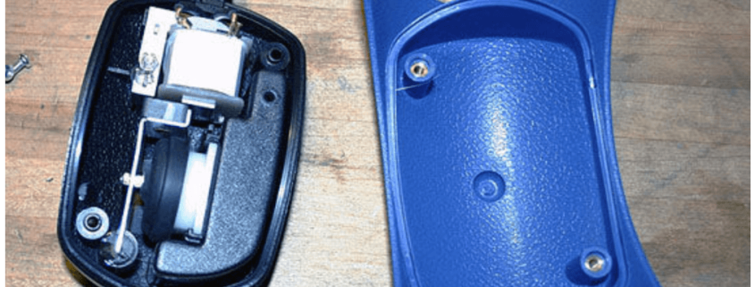
A servo is a handy device in robotics that converts electrical energy to mechanical energy. The device contains a two wire DC motor, a gear train, a potentiometer, an integrated circuit, and an output shaft. There are usually three wires attached to this device: a ground wire (which is usually black), an input voltage wire (which is usually red), and a control wire (which is usually yellow). Using the control wire, a coded signal is transmitted to the servo, which instructs the shaft to rotate to a specific angular position. The potentiometer can be thought of a variable resistor; its role in the servo is to monitor the angle of the shaft. If the shaft is not oriented at the correct angle, it will turn the motor to correct the direction. If the shaft is oriented at the correct angle, it will shut the motor off. A normal servo usually has the capability of positioning between the range of 0* and 180*.

pic1

Anatomy of a servo

The velociraptor will need eight servos: two for the head, two for the tail, and two for each leg. The two each on the head and tail will be for balancing purposes; left and right movements will be for balancing as each foot takes a step. The two per leg will be for not only walking, but a turning mechanism as well.

Calculations

pic2
Calculating servo torque

Torque is basically a “twisting force” and is measured in kg*cm. The larger this specification, the more force the servo can exert. If a servo has a power rating of 1 kg*cm, the maximum amount of power it will be able to apply with a 1 cm arm will be 1 kg.

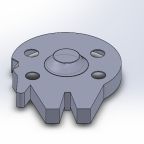
In application to the velociraptor, an estimation for total weight must be made in order to justify the purchase of the servo. For the MicroBiPed, the servo power rating was 3.5 kg*cm at 6.0 V. Thus, for an arm of 1 cm, the servo would be able to produce a 3.5 kg push or pull force to the right angle of the servo arm before stalling. Due to the torque dependency on arm length, the joints of the velociraptor should be kept close to the body to maximize force capabilities. Below is the Titrus III legs showing the arm lengths.

pic3
Titrus III arm lengths

The first prototype of the servo has a front arm length of 5.2 cm and back arm length of 2.0 cm. Using these numbers, calculations are made in the “Update” section of this blog post to calculate exactly how much weight each arm alone can handle. The Titrus III is credited and can be seen in action here: https://www.youtube.com/watch?v=GxVv4WNlXMA.

Trade-off Studies

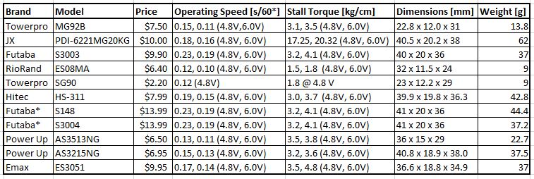
In order to better assess the appropriate servo to use for the velociraptor, a comparison chart was made below of servos in the marketplace.

pic4
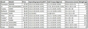
Servos comparison table

pic5
All servos, as per order in the comparison table

* The difference between the two Futaba servos is one has a bearing type of dual bronze brushings, and the latter has a signal ball bearing system.

The first listed servo is the one used by last semester, and the second is one with a lot of torque but Dr. Hill suggested not to go with. 11 different servos were compared, listing some of the most important characteristics. The velociraptor will need eight, so it is important to keep the cost of individual servos at a minimum. The operating speed shows how long it takes for the servo shaft to rotate 60*. It can be seen from the table that all operating speeds are relatively close in value, thus it will not be a major deciding factor. The stall torque is also an important parameter, which shows how much force is needed to move the shaft over a certain distance. In the case of a heavy velociraptor, the stall torque becomes a very important parameter as more torque is needed. The dimensions will affect how large the body encasing them will be. This information is important to M&D division for the size and shape of the body. Lastly, the weight is also significant, considering there are many servos to be accounted for.

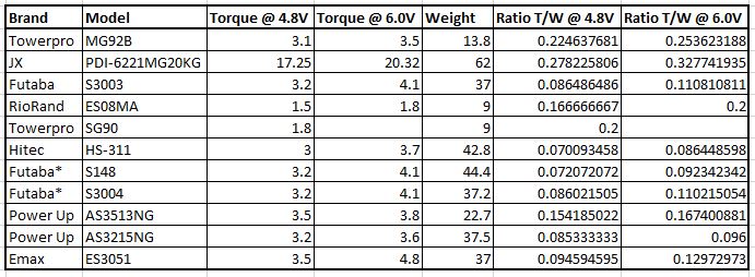
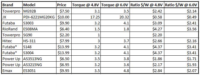
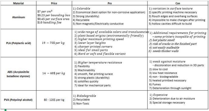
Observing the MicroBiPed, weight was undoubtedly the biggest problem. The choice of material used to construct the shell of the robot, PLA, made the overall “micro” robot very heavy as a result. The torque of the servos was not sufficient enough to power through the weight of the MicroBiPed. Thus, it is important that the velociraptor team is weight-conscious in selecting not only the material used to construct the shell, but also the individual component pieces. Below is a table comparing the stall torque to weight ratio of each component. Also below is the price to torque ratio.

pic6
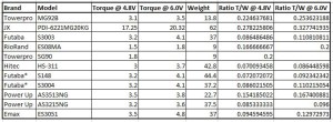
Stall Torque/Weight Ratios
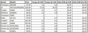
pic7
Price/Weight Ratios

Links to all the products:
[Towerpro MG92B] http://www.headsuphobby.com/Towerpro-14g-MG92B-Digital-Metal-Gear-High-Torque-SubMicro-Servo-A-537.htm
[JX PDI-6221MG20KG]  http://www.banggood.com/4X-JX-PDI-6221MG-20KG-Large-Torque-Digital-Coreless-Servo-For-RC-Model-p-1031156.html
[Futaba S3003] http://www3.towerhobbies.com/cgi-bin/WTI0001P?I=LXH288&P=8
[RioRand ES08MA] http://www.riorand.com/toys-hobbies/helicopters/riorandr-es08ma-9g-mini-metal-gear-servo-upgrade-mg90s-for-trex-align-450-rc-helicopter-e.html
[TowerPro SG90] http://www.amazon.com/J-Deal%C2%AE-TowerPro-Helicopter-Airplane-Controls/dp/B00X7CJZWM/ref=sr_1_1?ie=UTF8&qid=1455438532&sr=8-1&keywords=servos
[Hitec HS-311] http://www.headsuphobby.com/Hitec-43g-HS-311-Standard-Servo-B-560.htm?categoryId=-1
[Futaba S148] https://www.servocity.com/html/s148_standard_precision.html#.VsBN_fkrKM-
[Futaba S3004] https://www.servocity.com/html/s3004_standard_ball_bearing.html#.VsBOBPkrKM-
[Power Up AS3513NG] http://www.headsuphobby.com/Power-Up-25g-AS3513NG-Analog-Mini-Servo-W-350.htm?categoryId=-1
[Power Up AS3125NG] http://www.headsuphobby.com/Power-Up-38g-AS3215NG-Analog-Standard-Servo-W-400.htm?categoryId=-1
[Emax ES3051] http://www.headsuphobby.com/Emax-43g-ES3051-Digital-Standard-Servo-G-651.htm?categoryId=

Arduino Application

The servo library can be found on the Arduino website, which supports up to 12 different motors on most boards and up to 48 on the Arduino Mega. The Mega can handle up to 12 servos while the Mini can only handle 6-7, so the Mega might be in this semester’s project’s best interest. Two example codes are listed on the Arduino servo website for controlling the position of a servo with a potentiometer and for sweeping the shaft of the servo motor back and forth.

There are three different output types: analog voltage, PWM, and serial. Servo motors use the communication type of PWM (post width modulation). The length of a pulse in seconds will determine how many degrees the motor will turn, and in turn, dictates the angle of the output shaft.

pic8
Pulse duration’s relationship to shaft angle

Conclusion

Seeing as the velociraptor will require eight servos, it’s important to minimize weight as much as possible. The servo choice of the MicroBiPed provides the largest torque to weight ratio compared to all other options listed in the table. It’s even more notable that the dimensions are the smallest as well, which will keep the velociraptors body containing most of the servos sizable. To maximize the power ratings of the servos, the arm lengths should also be designed short.

Update (03/14/16)

After the systems and test engineer estimated the project to be around 350 g, torque calculations were able to be made to see exactly how much weight a single servo can handle. The front and back legs (“arm” joints) of the first prototype are 5.2 cm and 2.0 cm, respectively. Using the torque of the TowerPro MG92B servo at 3.5 kg*cm, it is calculated that the front servo alone can handle a weight of approximately 675 g and 1750 g, respectively. This is a basic calculation; of course there are other things to take into consideration like weight distribution of the velociraptor and the fact that some servos work together at the same time. However, this calculation shows that if a single servo can handle the weight of the entire project, then more than one servo (some working together simultaneously) definitely has enough torque to handle the project and then some. The total weight of the project, as estimated by the S&T engineer, is around 500 g. Thus, the TowerPro MG92B was the chosen servo for the velociraptor. All eight servos together come to a total of $60. This servo, also used by last semester’s MicroBiPed, also has the best torque-to-price and torque-to-weight ratio.

Works Cited

[1] What is a servo?
https://www.servocity.com/html/what_is_a_servo_.html#.VsAzEvkrKM8
[2] What’s a servo?
http://www.seattlerobotics.org/guide/servos.html
[3] How to Arduino #3 – Servos
youtube.com/watch?v=ybV8vitYAWU
[4] Servo Power & Speed
https://www.servocity.com/html/servo_power___speed.html#.VsBO9vkrKM8
[5] Understanding RC Servos: Digital, Analog, Coreless, Brushless
http://www.rchelicopterfun.com/rc-servos.html
[6] Servo library
https://www.arduino.cc/en/reference/servo
[7] Titrus III
youtube.com/watch?v=GxVv4WNlXMA

Spring 2016 Velociraptor: Sensors

By: Ashlee Chang (E&C)

Updated: 04/05/16

Table of Contents

Fulfilling the Requirements

Level 2 requirements #9 and #10 are stated as follows:

9. For the Velociraptor to have the ability to travel up a 6.5-degree incline, a gyroscope/accelerometer shall be implemented to preserve the chassis balance and thus meeting the Project Level 1, requirement 6.

10. In order for the robot to detect obstacles at a range of 20 cm in its path, an ultrasonic sensor shall be implemented to the build of the Velociraptor and thus meeting the Project Level 1, requirement 7. 

Thus, the two sensors that will be implemented on the Velociraptor will be an ultrasonic sensor and a gyroscope/accelerometer. Below are the trade-off studies conducted, analyses on the best option, and the team’s final decision.

How the Sensors Work

Ultrasonic Range Finder

Ultrasonic sensors use a process called echolocation, which uses sound as a form of location. A high frequency sound wave is generated; the time it takes for the sound to bounce off an object and back to the sensor determines the distance away from the object it is.

Gyroscope/Accelerometer

A gyroscope/accelerometer is a device to measure acceleration forces. Using this information, one can determine the plane at which the robot is tilted at with respect to Earth. It has crystal structures contained within it that generates vibrational stress to acceleration, inducing a voltage level reading.

Trade-off Studies

Ultrasonic Range Finder

tradeoffultrasonic

Ultrasonic Sensors Comparison

The first option is the component used for last semester’s MicroBiped. The neck and head length of the velociraptor will be approximately 15-20 cm long, which is the minimum distance the ultrasonic sensor must be able to detect. All of the ultrasonic sensors compared have at least a 2 cm minimum range. The velociraptor must be able to respond to an object forward-facing it, most likely 5-10 distance away from the end of its head. All of the maximum ranges for the ultrasonic sensors are well over 400 cm, which makes any of the options fine. Most standard sensors have a dimension of 50 x 15 x 14 mm, weight 10 g, need a 5 V power supply, and generate ultrasonic waves at 40 kHz. The resolutions range from 0.3 to 1 cm, all which are exceptional as the Arduino coding can be set up to respond at any point. The angle at which the echoes can bounce back is documented in the last column of the table. The RB-See-90 has an angle measurement double than the other ultrasonic sensors, but is also 5x the price. As demonstrated below, as the velociraptor approaches the hindering obstacle, the obstacle takes up a wider view within the vision of the ultrasonic sensor. Thus, a measuring angle of 15* is sufficient. These ultrasonic sensors use a PWM interface; a 10 micro-s pulse will initiate the ranging, and a pulse duration is outputted based on if and how far an object is away. The calculation for distance is Distance = [(Duration of high level)*(Sonic 340 m/s)]/2.

pic3

Measuring Angle and Distance

  • List of Products:
[SainSmart HC-SR04]: http://www.sainsmart.com/ultrasonic-ranging-detector-mod-hc-sr04-distance-sensor.html

[Banggood HY-SRF05]: http://www.banggood.com/HY-SRF05-Ultrasonic-Distance-Sensor-Module-Measuring-Sensor-Module-p-91444.html?currency=USD&createTmp=1&utm_source=google&utm_medium=shopping&utm_content=saul&utm_campaign=Electronic-xie-us&gclid=CK7pwoHpissCFYVCaQodpXIBbw

[GearBest HC-SR04]: http://www.gearbest.com/development-boards/pp_58067.html?currency=USD&gclid=CIeQwMrsissCFYM8aQodFM4FOw

[SeeedStudio RB-See-90]: http://www.robotshop.com/en/seeedstudio-ultrasonic-range-finder.html?gclid=CJ7LmePtissCFYSDaQodBvQOsg#productsReviewBoxTitle

[MaxBotix MB1030]: http://www.maxbotix.com/Ultrasonic_Sensors/MB1030.htm

Gyroscope/Accelerometer

gyroacceltradeoff

Gyroscope/Accelerometers Comparison

With accelerometers, there is a trade-off between the measuring range and its sensitivity. A smaller range will provide a more accurate reading, but won’t be able to handle higher velocities, and vice versa. For stationary tilting. Range notation is written as +#g. For tilting, +1.5g is recommended, robots +2g is recommended, for sudden stops +5g is recommended, and for vehicles such as a spaceship +250g is recommended. So the choice in range for the velociraptor should at least +2g. The weight and dimensions of the accelerometers are all similar, and won’t be a factor in the final decision. Ideally, a PWM output type would be ideal to work with in the Arduino because of its simplicity. However, all accelerometers researched seemed to either have an analog or a serial interface; the serial interface uses SPI (serial peripheral interface) and I2C (inter-integrated circuit). The E&C division manager recommended not to use such interface as it is difficult to master dealing with such data. Analog Device’s ADXL335 supports an analog interface, which will provide data that will be easy to work with.

  • List of Products:
[Freescale Semiconductor MMA8451]: https://www.adafruit.com/products/2019?gclid=CISlz8P1issCFQmQaQodjKwLqQ

[Freescale Semiconductor MMA8452Q]: http://www.robotshop.com/en/triple-axis-accelerometer-breakout-board-mma8452q.html?gclid=CNfjjqWEi8sCFQmqaQodNSYPGQ

[Analog Devices ADXL345]: https://www.adafruit.com/products/1231

[Analog Devices ADXL335]: https://www.sparkfun.com/products/9269

[Kootek GY-521]: http://www.amazon.com/Kootek-MPU-6050-MPU6050-sensors-Accelerometer/dp/B008BOPN40

Conclusion

pic5

GearBest HC-SR04 and Analog Device ADXL335

The sensors the velociraptor team would like to go with are GearBest’s HC-SR04 ultrasonic sensor and Analog Device’s ADXL335 accelerometer. The former was chosen based on an economical decision, as all ultrasonic sensors met the requirements in distance detection, resolution, and angle sensitivity. The latter was chosen because it not only has a more than sufficient measurement range of +3g, but also outputs analog data, a much easier interface to work with over SPI and I2C.

Update: Due to unforeseeable circumstances, the velociraptor team had to make some changes regarding the sensor choices. In regards to the ultrasonic sensor HC-SR04, the sensor was no longer functional once the object in front was out of range capability. Most HC-SR04s cheaply manufactured in China overlooked this important flaw. Once a high frequency wave was sent out, the sensor would standby and wait until this wave bounced off the object and returned. With no object in front of the sensor, the HC-SR04 would continue waiting. A clap of the hands or even shaking the sensor would act as a return signal, and the Arduino serial monitor would stop returning the error value -1. This is why the velociraptor team decided on investing in a nicer, better quality rangefinder that met the velociraptor requirements. The E&C division manager had a quality ultrasonic sensor on-hand, which our team purchased. For the gyroscope/accelerometer, there was miscommunication on what sensor was to be used for sensing orientation. Initially the team was told to use an accelerometer, hence the ADXL335 choice. However a couple weeks ago, the team was informed that a gyroscope was to be used, as analog inputs are actually more difficult to handle. Testing the GY-521 gyroscope/accelerometer combination board, a sample code was uploaded provided online, which was hundreds of lines long, using serial output type. Upon uploading to the Arduino, the code took up over an outstanding 50% of flash memory. Because the current walking code and Bluetooth code are approximately 20% each already, the team saw using this serial output type orientation sensor as unfeasible. Therefore, the team is sticking with the ADXL335 choice. Both the MaxSonar ultrasonic sensor and ADXL335 accelerometer codes have been tested and work successfully with some degree of accuracy.

IMG_4506

MaxBotix LV-MaxSonar-Ez3 MB1030 and Kootek GY-521

Works Cited

[1] Ultrasonic transducer: https://en.wikipedia.org/wiki/Ultrasonic_transducer

[2] Accelerometer: https://en.wikipedia.org/wiki/Accelerometer

[3] A beginner’s guide to accelerometers: http://www.dimensionengineering.com/info/accelerometers

[4] Accelerometer, Gyro and IMU Buying Guide: https://www.sparkfun.com/pages/accel_gyro_guide


Spring 2016 Velociraptor: Material Trade-Off Study

By Mingyu Seo (Manufacturing & Design)

Approved by Khoi Vu (Project Manger)

For the Velociraptor Project, we have considered several materials for manufacturing prototypes as well as for our final robot. The chart shows advantages and disadvantages of the material, to help us consider the different materials we’ll use for the velociraptor:

Capture

Through careful consideration, we chose to use 3D material to build our prototype. Using a 3D printer will give use the advantages of faster printing speed, quick solidification, and are easily accessible. 3D materials shown above such as PLA, ABS, and PVA are flexible, strong durability, and have sharp printed corners which are made for ideal small parts. Although the plastic material may have lower temperature resistance compare to Aluminum, building a prototype with a 3D model will let us make adjustments by applying heat to it.  We have considered using PLA (Polylactic Acid) material due to its advantages of sharper printing corners, low material cost, maximum printing speed, and accessibility on campus. All 4 materials were considered as a possible material for our final robot. But Aluminum was chosen to be used as the material to build the final robot due to its economical, strong durability and non-magnetic/electrical conductive traits. Due to aluminum’s disadvantages of the necessity of specific printing machine and non-malleability, our team has considered it should be used after finalization of the dimension of our robot in order to minimize cost as well as time.