By: Bao Loc Doan (Project Manager)
Christine Vu (Systems Engineer)
Henry Nguyen (Electronics Engineer)
Nasser Alsharafi (Manufacturing)
Program Objectives/Mission Profile
by Bao Loc Doan (Project Manager)
Program Objective Statement
When humans manually pick and place surface mount components onto a printed circuit board (PCB), there are problems with human accuracy and time efficiency. A pick and place surface mount device (SMD) is an automated device that can populate a PCB with surface mount components (resistors, capacitors, and IC chips) by referencing a Gerber file through the use of software. The pick and place SMD machine will be able to pick up the surface mount technology (SMT) components from 8 mm reel feeders and an integrated circuit (IC) tray and place the components down at the correct location until the board is finished. The customer has expressed the desire to create a pick and place SMD machine that can populate surface mount components as small as 0402 on all EE400D boards of Spring 2016 with the same specifications as the Madell Corporation Model DP2006-2. The customer has expressed the desire to keep the budget of the project below $650 and finished before the end of Spring 2016.
Mission Profile
Once a gerber file provided by any project from EE400D up until Spring 2016 is uploaded, the pick and place SMD machine shall begin populating SMT components from four 8 mm reel feeders and one IC tray onto the PCB. The smallest SMT component that will be placed is component size 0402. The pick and place SMD machine will be modified from a Makeblock XY plotter and replicate the error specification of the Madell Corporation Model DP2006-2.
Requirements
Level 1 Program/Project Requirements
by Bao Loc Doan (Project Manager)
To satisfy our customer, a list of requirements that our end product needs to meet were created. These requirements will move the design forward and provide traceability to our program objectives and mission profile.
- The pick and place SMD machine shall be able to assemble all EE400D PCB’s by the end of Spring 2016.
- The pick and place SMD machine shall pick up a component and place down a component with a maximum of 0.05 mm error (specification of Madell Corporation Model DP2006-2).
- Software for the pick and place SMD machine shall accept all Gerber files of EE400D projects up until Spring 2016.
- The pick and place SMD machine shall have four 8mm reel feeders and one IC tray.
- SMT component size 0402 shall be the smallest component that the pick and place SMD machine can pick up.
- Total cost of finished project must be under $650.
- Deadline to complete the pick and place SMD machine shall be before the end of Spring 2016.
Level 2 System/Subsystem Requirements
by Christine Vu (Systems Engineer)
Level 2 System and Level 2 Subsystem Requirements are listed below. The process of forming requirements is not only crucial to the overall design of the project but also difficult to form due to the customer’s needs and the nonlinearity of designing. Through many revisions, the level 2 requirements were officially determined. Because this project is new to the Arxterra blog, references were obtained through scholarly journal research and outside resources other than the Arxterra blog.
Source Material:
Arra, M. , Geiger, D. , Shangguan, D. , & Sjöberg, J. (2004). A study of smt assembly processes
for fine pitch csp packages. Soldering & Surface Mount Technology, 16(3), 16-21.
CadSoft Computer GmbH and CadSoft Inc. (2011). EAGLE Freeware. Retrieved from:
http://www.cadsoftusa.com/download-eagle/freeware/
Changzhou Douwei Electric Co. Ltd. (n.d.). 42BYG Stepping Motor. Datasheet.
Makeblock. (2014, June 9). XY Plotter 2.0 How it works? Retrieved from:
https://www.youtube.com/watch?v=gY0xMYrWBDg
Panasonic. (2014, Feb. 4). Precision Thick Film Chip Resistors. Datasheet.
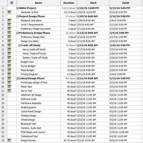
Shenzhen Maker Works Technology Co., Ltd. (2013). X-Y Plotter Robot Kit. Retrieved from:
http://www.makeblock.cc/xy-plotter-robot-kit/
TCI Precision. (2005). Blanchard Grinding. Retrieved from: http://tciprecision.com/machine-ready-blanks/capabilities/Blanchard%20Grinding
Telecommunications Industry Association. (2001). TIA/EIA-568-B.1: Commercial Building
Telecommunications Cabling Standard.
VBsProjects. (2014, July 12). Homemade SMD Pick and Place Machine – complete cycle.
Retrieved from: https://www.youtube.com/watch?v=CRSLbo_8nTQ#t=7m34s
Notes on Requirements:
L2 – # – Level 2 System Requirements (i.e. L2 – 1)
L2 – #x – Level 2 Subsystem Requirements (i.e. L2 – 1a)
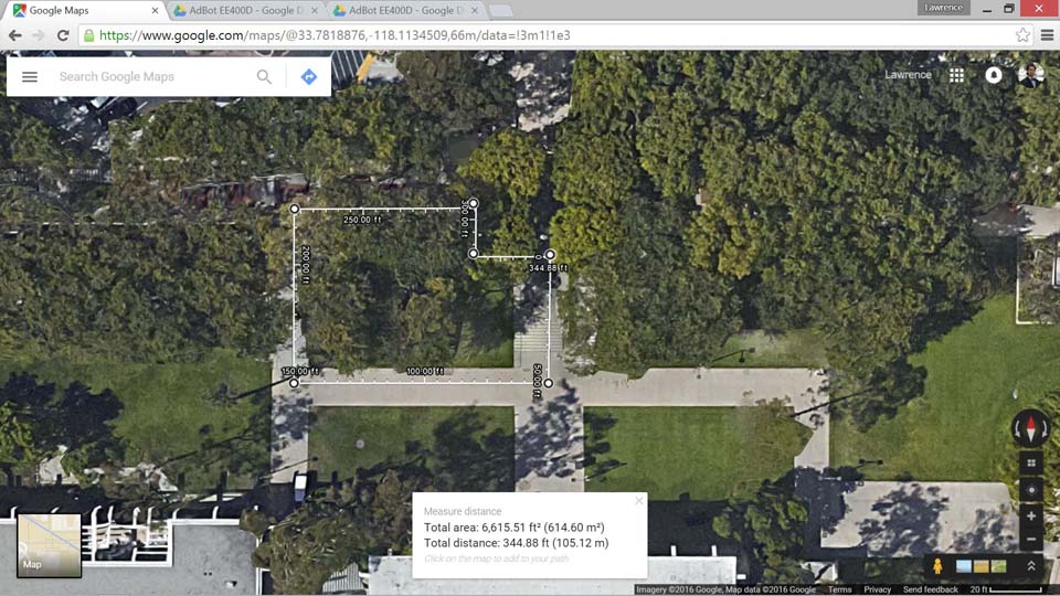
L2 – 1 Working area must be within 12.2”x15.35” (310mmx390mm) based on the Makeblock X-Y Plotter.
Explanation: The MakeBlock X-Y Plotter Robot Kit design specifications indicated the working area size as shown above (Shenzhen Maker Works Technology Co., Ltd., 2013). The working area is the area that the motors can move. This requirement will be verified through the use of a measuring tape tool. Tolerances will be taken account depending on the measuring tape that will be used.
L2-1a Working Area shall fit a 4″ x 3.2″ PCB for EE400D students.
Explanation: EE400D Students will be using EagleCAD software to design their PCB.
The free version limits the PCB design size as 4” x 3.2” (CadSoft Computer GmbH and CadSoft Inc., 2011). This can be verified by the use of a measurement tape tool.
L2-1b Surface to hold PCB shall be smooth with dimension tolerances to ±.001″, parallelism to .001″, and flatness to .001″.
Explanation: The process to place SMT components will begin with the application of solder paste by hand. This requires a very smooth surface that may require Blanchard grinding. These tolerances were taken from industrial Blanchard grinding standards (TCI Precision, 2005). This will be verified from the company that we plan on using.
L2-1c PCBs laid out for assembly shall be on a surface at 0° with respect to the floor. A test shall be used to determine a safe tolerance.
Explanation: To improve precision, it is important to ensure that the machine will run in a straight line and parallel to the floor. This will keep the SMT components from falling off the PCB. A digital leveler will be used. Tolerances will depend on the leveler used.
L2-1d All wires shall refrain from contact with the working surface.
Explanation: The Makeblock X-Y Plotter lacks the placement of wires. During plotting, wires are touching the surface (Makeblock, 2014). This should be avoided due to the addition of more wires, reel feeders, and IC trays in the working area. Wires dragging against the surface may also cause problems with wire protection.
L2-1e All wires using RJ25 connectors shall have a minimum bend radius of 4x its diameter.
Explanation: The pick and place SMD machine has repetitive movement, where a vacuum system will pick up a SMT component and place it down a PCB one at a time. Since wires will be moving along the vacuum system, repetitive movement may affect the lifespan of the wires. Therefore, a general rule-of-thumb to prevent wire fatigue is to set a minimum bend radius of 4 times its diameter (Telecommunications Industry Association, 2001). The bend radius shall be measured from the start of the curve to the end of the curve using measuring tape. Tolerances will depend on the tool being used.
L2-1f A clamping system shall hold all PCBs for EE400D students with maximum size 4″ x 3.2″.
Explanation: A clamping system will provide stability when the vacuum system is placing down the SMT components and indicate the maximum PCB size 4” x 3.2”, which is the limited PCB size for the free version of EagleCAD (CadSoft Computer GmbH and CadSoft Inc., 2011). This will be verified by clamping a 4” x 3.2” PCB. The clamped PCB should not be able to move once the machine is operating.
L2 – 2 The pick and place SMD machine shall pick up and place down all required integrated circuit chips according to EE400D PCB’s provided up until Spring 2016.
Explanation: The purpose of a pick and place SMD machine is to assemble a PCB design given by EE400D Students. It is important to note that integrated chips will also be placed down. This will be verified by the provided Gerber file.
L2-2a A vacuum system shall pick up all required IC chips according to EE400D PCB’s provided.
Explanation: A vacuum system is the subsystem that will be used to pick up SMT components such as the integrated circuit (IC) chip. It also indicates that a vacuum system must be strong enough to hold the IC chip. This will be verified by testing the worst-case scenario, where the heaviest IC chip will be picked up by the vacuum system. Explanation of the duration will be indicated in the next requirement, L2-2b.
L2-2b Duration of suction to pick up IC chips shall begin from picking at IC tray to the placement on the PCB.
Explanation: Although picking up the SMT components are lightweight, it may be important to verify the duration of how long the vacuum system takes to pick up a component and place it on the PCB. A stopwatch will be used to time the process.
L2-2c A solenoid valve shall close airway of the vacuum tubing each time IC chips are placed down.
Explanation: The vacuum system will be controlled through the opening and closing of a solenoid valve. This can be verified by testing the software to control the solenoid valve picking and placing the IC chip. This requirement is also noted for the rest of the SMT components in L2-8b.
L2 – 3 Pick and place SMD machine shall self-correct all orientation of IC chips before placement.
Explanation: This requirement is to ensure that the pick and place machine is able to auto-orientate IC chips in case the chip is placed incorrectly on the IC tray. This can be verified through testing of the worse-case IC chip.
L2-3a A sensor area shall detect the number of pins on IC chips.
Explanation: A feature that may be included to support our pick and place SMD machine is to create an area to correct the configuration of the IC chip when it is removed from the IC tray. This idea was based on one of a homemade pick and place SMD machine (VBsProjects, 2014).
L2-3b In order to keep suction of the IC chip after pick-up, all IC chips shall be rotated about the A-axis.
Explanation: As stated in L2-3a, it is important to note how the IC chip will be corrected. That is, a motor may be used to move about the A-axis. VBsProjects (2014) demonstrates how the IC chip will be corrected. This will be verified by test – an IC chip will be picked up by the vacuum system and taken to the sensor area, where it will be corrected.
L2 – 4 Makeblock X-Y Plotter motors shall be modified to a maximum of 0.05 mm error.
Explanation: The Makeblock X-Y Plotter online specifications indicate that the precision error is 0.1 mm (Shenzhen Maker Works Technology Co., Ltd., 2013). Calculations may be verified based on the distance between the SMT mounting holes (Arra etc., 2004).
L2-4a Resolution of all axes motors shall be less than 1.8°/step.
Explanation: The Makeblock X-Y plotter uses 42BYG Stepper motors to control the x-axis and y-axis, which indicate a resolution of 1.8°/step (Changzhou Douwei Electric Co. Ltd., n.d.). To improve the precision, a possible solution is to switch the stepper motors into better ones. This may be verified through the use of datasheets.
L2-4b Z-axis motor shall move the vacuum system at 90° with a tolerance of 1° with respect to the floor.
Explanation: The Z-axis control on the Makeblock X-Y plotter uses a servo motor that moves up and down at an angle (Makeblock, 2014). If the z-axis is not modified, then the vacuum tubing may be bent and the vacuum system will not function properly if it is picking up the SMT components at an angle.
L2 – 5 Software shall translate all Gerber files from EE400D PCB’s to G-Code files.
Explanation: The Makeblock X-Y Plotter plots using G-code files. Arduino sketches have already been made to control the motors.
L2-5a Software shall include all x-y coordinates for pick and place SMD machine to read.
Explanation: G-Code will be viewed on CNCViewer, a program that can present the locations of the SMT components on a PCB.
L2 – 6: All SMT resistors and capacitors shall remain in cut-tape of the reel feeders until the vacuum nozzle is ready to pick up the component.
Explanation: This requirement is to acknowledge that the reel feeders are secure and in place. This will be verified using a checklist – determine whether the vacuum nozzle moves other SMT components when the nozzle picks up one SMT component, determine whether the motors cause vibrations of the working area, and determine whether the SMT components will be isolated while the system is placing the components.
L2-6a Reel feeders shall be placed within working area, 12.2”x15.35”(310mmx390mm).
Explanation: Because our working area is confined to the Makeblock X-Y Plotter Robot Kit (Shenzhen Maker Works Technology Co., Ltd., 2013), the vacuum system must be able to reach the SMT components. Therefore, the reel feeders must be placed in an area where it is reachable.
L2-6b Bracket to hold cut-tape of the reel feeders shall be higher than 1.10 mm.
Explanation: The reel feeder tape specifies the tape thickness to be 1.00 ± 0.10 mm (Panasonic, 2014). In order to hold the reel feeders in place, the bracket should be higher than this. This can be verified by placing the reel feeders in the bracket.
L2-6c Micro servos shall automate all reel feeders.
Explanation: The pick and place SMD machine shall be automatic; therefore, a motor would be used to control each of the reel feeders. A trade-off study will be conducted on micro-servos.
L2-6d All micro servos shall remove plastic covering from the reel feeder.
Explanation: A solution to control the feeder is to have a pulley attached to the micro servos. A specification on a pulley shall be determined.
L2 – 7: IC tray shall store all IC chips required for one PCB assembly.
Explanation: The worst-case scenario will be used to determine the size of the IC tray.
L2-7a IC tray shall be placed within working area, 12.2”x15.35”(310mmx390mm).
Explanation: Similar to the L2-6a, the vacuum system must be able to reach the working area of the Makeblock X-Y Plotter Robot Kit (Shenzhen Maker Works Technology Co., Ltd., 2013).
L2 – 8: Vacuum system shall be able to pick up all SMT components as small as size 0402.
Explanation: This requirement was based on the customer requirement to pick up small components. This will be verified by picking up the SMT component size 0402.
L2-8a Vacuum nozzle shall be smaller than 0.50 ± 0.05 mm.
Explanation: The nozzle size is based on the smallest component to pick up, which is 0402. According to the datasheet, SMT size 0402, 0.05 0.50 ± 0.05 mm (Panasonic, 2014)
L2-8b A solenoid valve shall close airway of the vacuum tubing each time SMT resistor and capacitor components are placed down.
Explanation: Similar to L2-2c, a solenoid valve will be used to control the passageways of the vacuum tubing. A test shall be conducted to control the solenoid valve with ArduinoUno.
Design Innovation
Creativity Presentation
System/Subsystem Design
Product Breakdown Structure
By Christine Vu (Systems Engineer) and Henry Nguyen (Electronics Engineer)
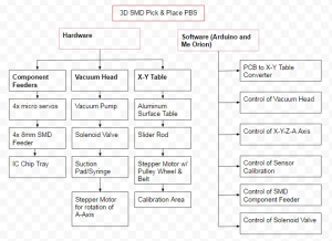
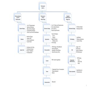
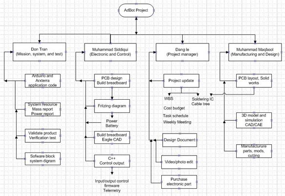
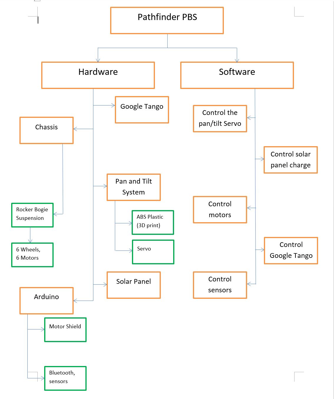
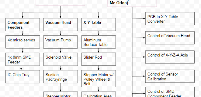
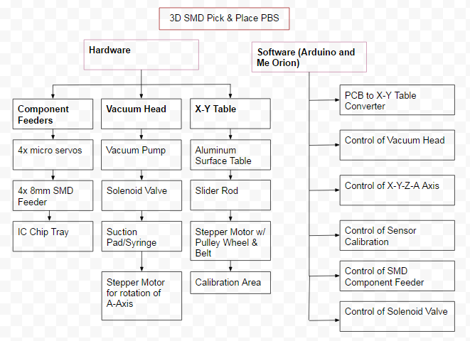
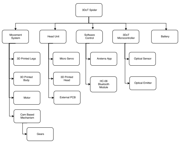
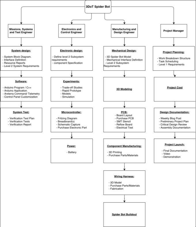
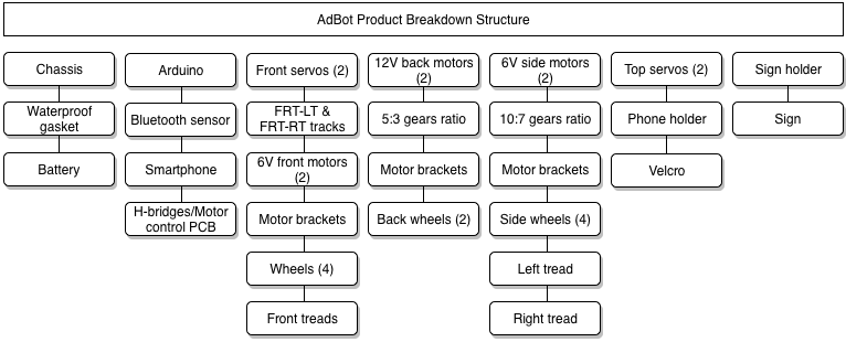
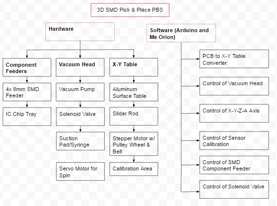
Figure 1. Product Breakdown Structure
The Product Breakdown Structure (PBS) shows all the functional blocks of our pick and place 3D SMD machine. The hardware is split into three different categories: Component Feeders, Vacuum Head, and X-Y Table. We will need a minimum of 4x micro servos to control our 4x 8mm reel feeders and an IC chip tray. The Vacuum head will consist of a vacuum to suction the components, a syringe or vacuum pen to pick up our components, a solenoid valve to block airflow and allow our components to be placed, and finally a stepper motor for rotation of the A axis. The X-Y Table is purchased from MakeBlock; however, we will need an aluminum surface table, slider rods, stepper motors, and calibration sensors to orientate our components. For software, we plan on using Arduino to program the Arduino Uno and Me Orion microcontrollers. Software must be able to convert Gerber files into G-code which can be read by our Me Orion microcontroller. We will need to be able to control all axis of our machine, the calibration sensor, component feeders, and solenoid valve through software.
Electronic System Design
by Henry Nguyen (Electronics Engineer)
Source Material
Me Orion:
- Schematic:
- Specifications:
Me Stepper Driver:
- Schematic:
- Specifications:
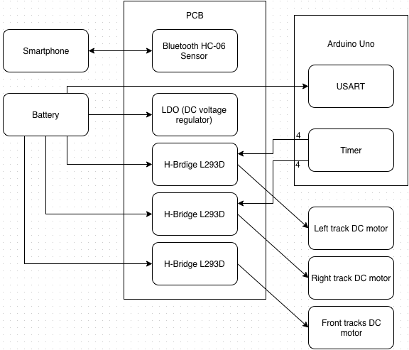
System Block Diagram
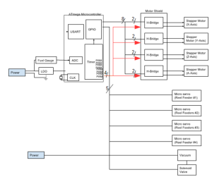
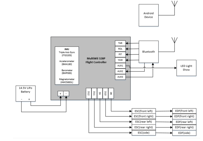
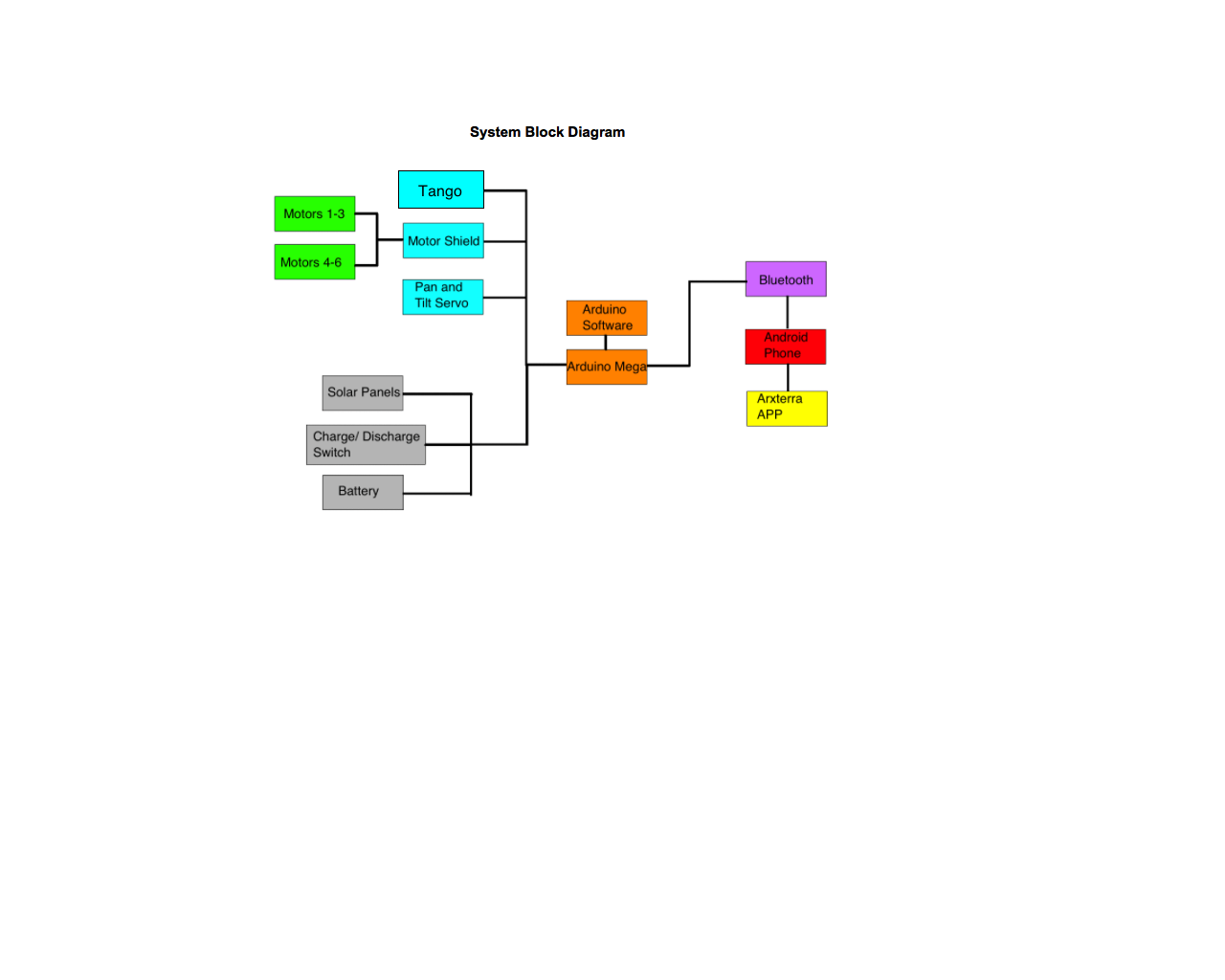
Fig. 2. System Block Diagram
The image above is the system block diagram for our pick and place 3D SMD Machine. We will have 4 stepper motors, 4 micro servos, a vacuum, and a solenoid valve as our actuators. The 4 stepper motors are used to control our axis on our machine. We will have a X,Y,Z, and A axis. The A axis is for the rotating our vacuum nozzle in order to orientate our integrated circuits in the right position to place onto our PCB. We will also have 4 micro servos to control our reel feeders. We are planning on using these servos to move our components forward after our machine picks up the component from the reel feeders. The solenoid valve is to control our vacuum. Our vacuum will be constantly running on a separate power source. The solenoid valve will close off the vacuum to prevent suction. This will allow our components to be placed onto our PCB after our machine picks it up.
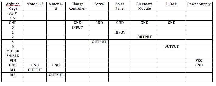
Interface Definition
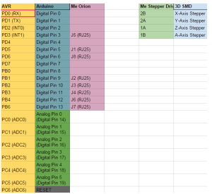
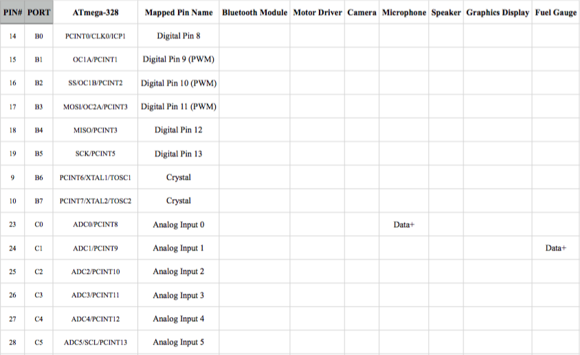
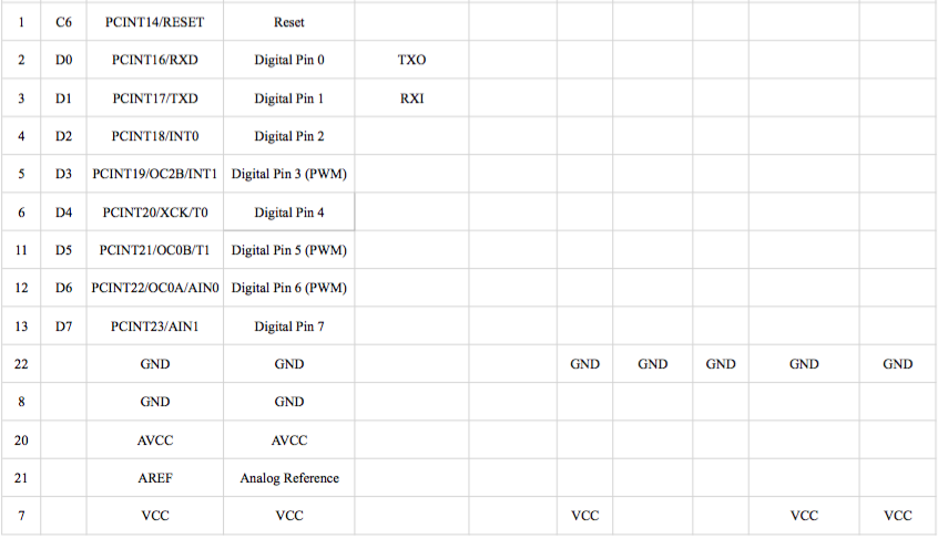
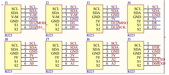
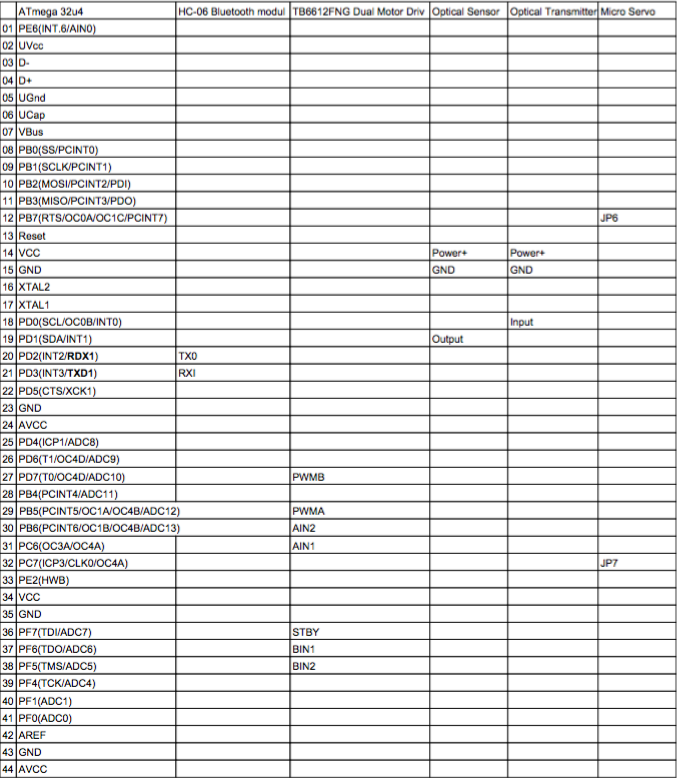
Fig. 3. Interface Matrix
The image above is the interface matrix for our pick and place 3D SMD machine. We will be utilizing an Arduino Uno, Me Orion, and Me Stepper Driver. Me Orion and the Me Stepper Driver came with our X-Y Plotter. This Me Orion is based off of an Arduino Uno, which will allow us to code using Arduino, Scratch. and AduBlock. We will be using this microcontroller because it has 8 RJ25 ports which will be useful for all of our actuators. The Me Stepper Driver will be used to precisely control our stepper motors by operating our motors in full, half, quarter, eighth, and sixteenth step modes. This modes can be easily changed using the built-in DIP Switch. We will need 4 Me Stepper Drivers in order to control all of our stepper motors on each axis (x,y,z,A).
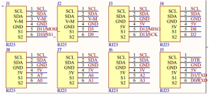
Fig. 4. Me Orion Schematic
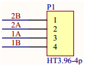
Fig. 5. Me Stepper Driver Schematic
Specification for Me Orion:
Operating Voltage: 6-12V DC power;
Microcontroller: ATmega238;
Detecting Angle: prefer at 30 degree angle;
Dimension: 80 x 60 x 18 mm (Length x Width x Height);
Specification for Me Stepper Driver:
- Max current: ±1.35A
- Max motor drive voltage: 25V
- Note: Me BaseBoard max supply voltage 12V
- Logic voltage: 5V
- Dimensions: 48mm*24mm(Length × Width)
Mechanical Design
By Nasser Alsharafi (Manufacturing)
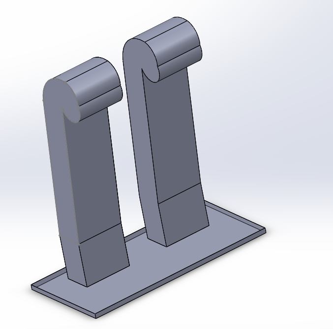
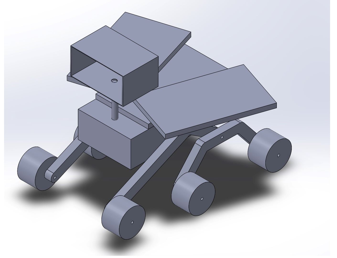
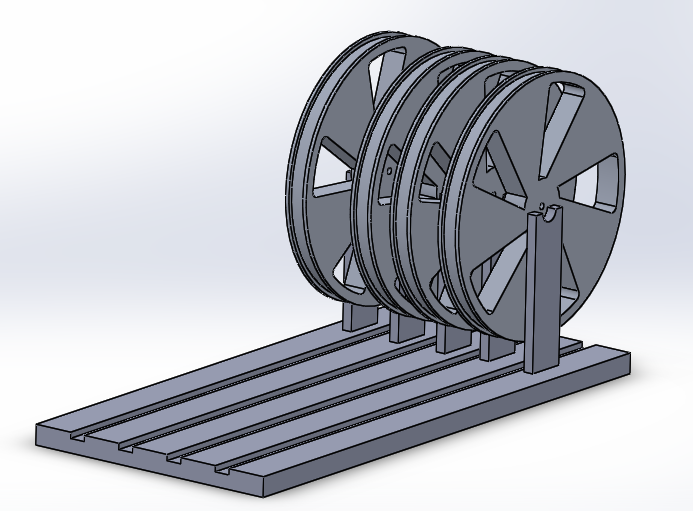
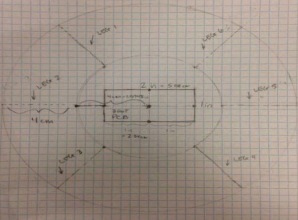
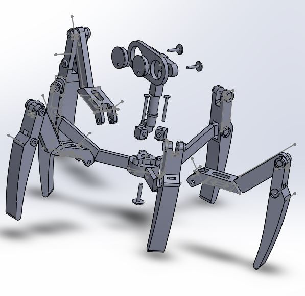
In this part of the project for the XY plotter I am coming up with the design of a Reel Feeder. The main purpose of a reel feeder is to feed the machine with the surface mounted parts. The reel feeder is made of aluminum. The main function of the Reel Feeder wheel is to roll and pass on the parts to the Reel Feeder base, which then the parts will be picked up by the vacuum.

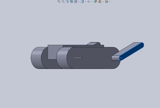
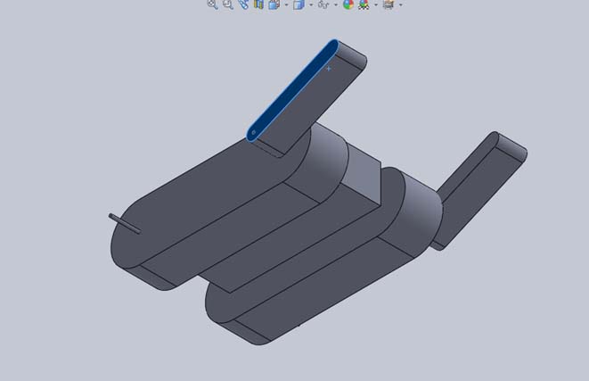
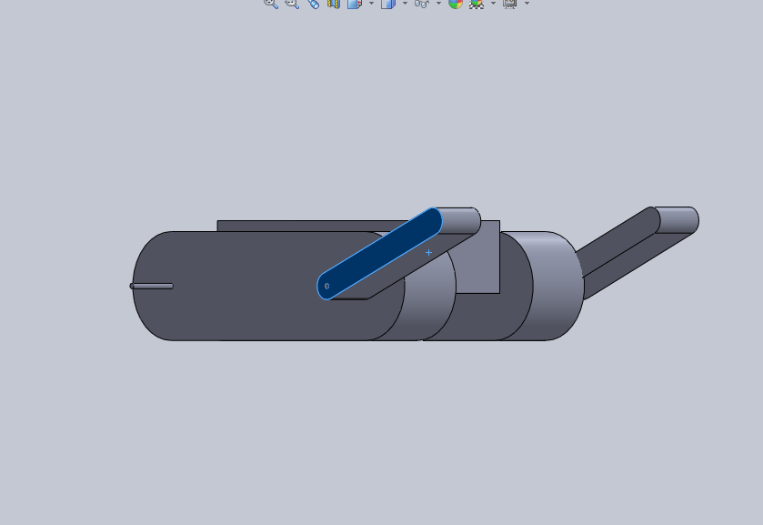
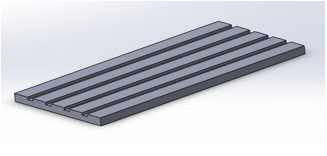
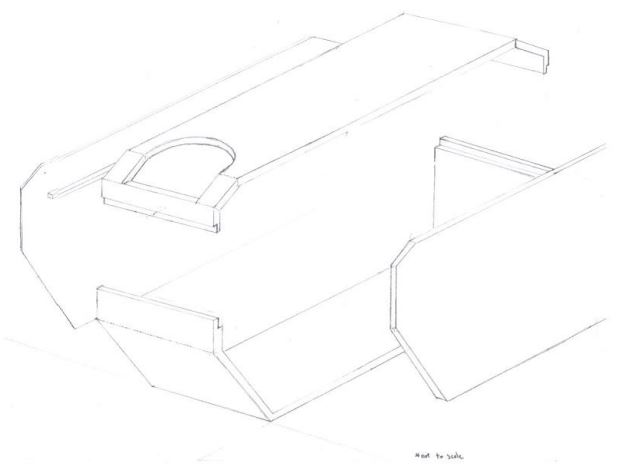
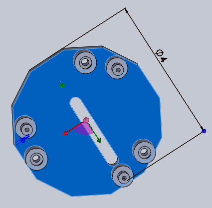
Fig. 6. Complete reel feeder assembly 3D model

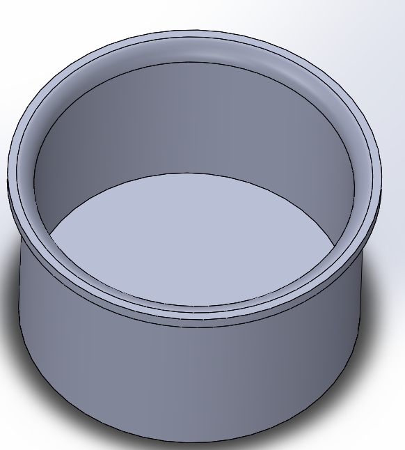
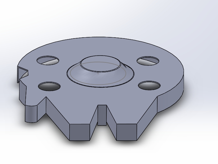
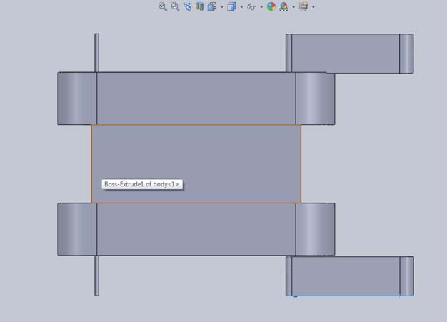
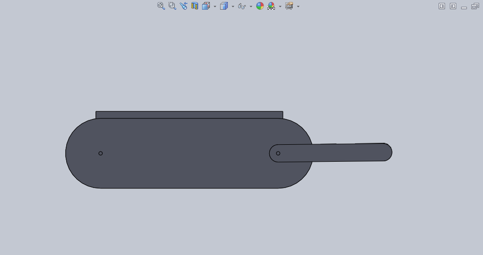
Fig. 7. Reel feeder base
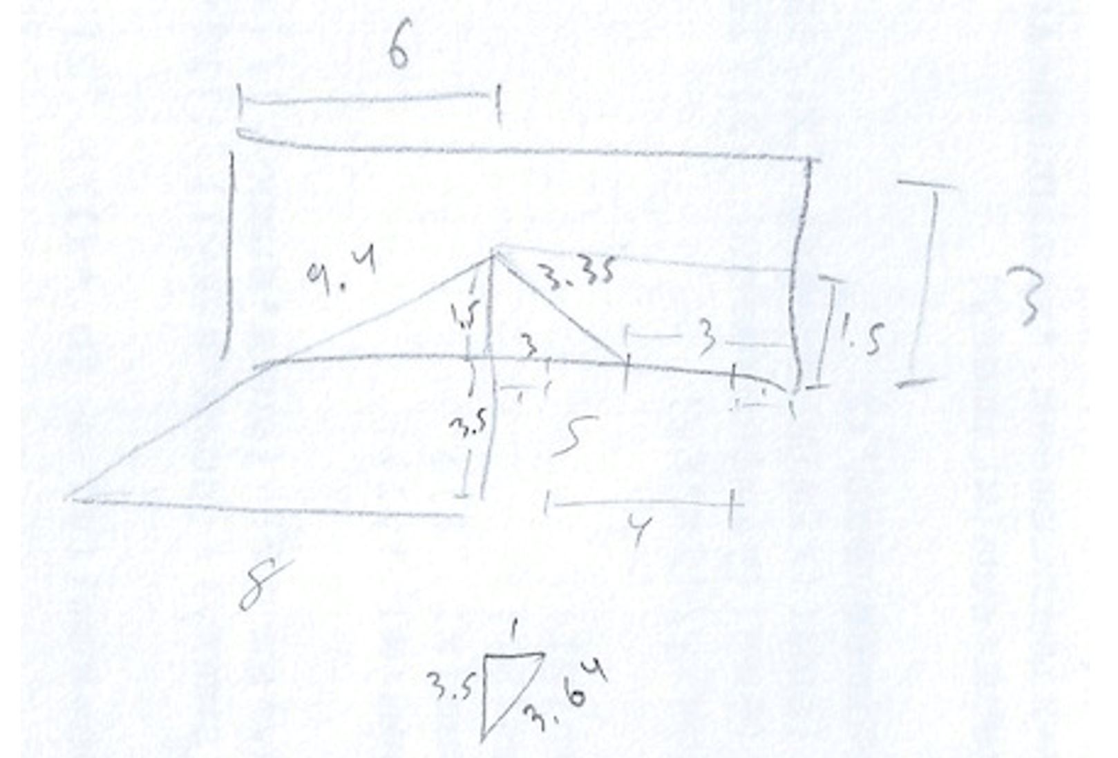
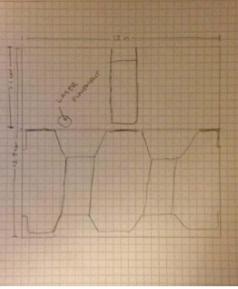
The base sheet of the reel feeder has four channels called the grooves in which the tape passes through. The base sheet of the reel feeder has a length of 270 mm and a width of 82 mm. Each of the grooves on the base sheet of the reel feeder has a width of 8 mm. The main function of the reel feeder is to guide the tape to the part of the feeder where the chip is first pulled and then picked by a vacuum pen. This action helps in preparation of the next chip. After, the chip is taken by the vacuum pen and is placed on the PBC board.
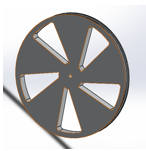
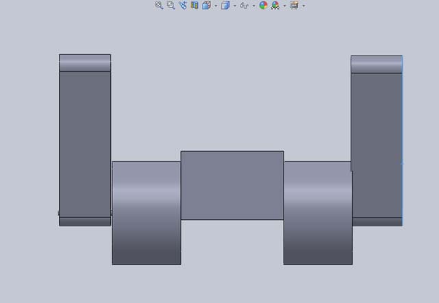
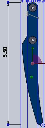
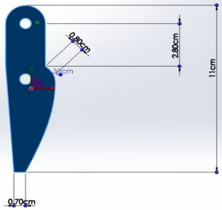
Fig. 8. Reel feeder wheel

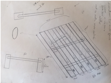
Fig. 9. Drawing of initial reel feeder base
Currently, our reel feeder is manual, so there can be further improvements by making the reel feeder automatic. In order to make the reel feeder automatic, I have to design a mounting bracket for 4 micro-servos. Each channel has single micro-servo to pull back the tape while pushing the reel forward. This will be implemented by working with Henry Nguyen to control the micro-servos.
Design and Unique Tasks
By Henry Nguyen (Electronics Engineer)
- Work with our X-Y Plotter and given programs in order to see how to control our actuators through software (02/19/16 – 02/28/16).
- Research Flatcam which can take Gerber files and generate G-Code for isolation routing.
- This is for our precision software that will tell our machine exactly where to pick and place components (02/19/16 – 02/28/16)
- Look for local connections and prices for our aluminum surface table by 02/28/16.
- Review DIY tutorials on how to configure an aquarium pump into a vacuum system (02/22/16).
- Understand how to define actuators and power subsystems.
- President Watts said he will review this in our division meeting (02/20/16).
- Research how to incorporate gyro, accelerometer, and/or magnetometer into inertial measurement unit in order to measure the angular rotation of our A-axis stepper motor (03/18/16).
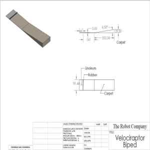
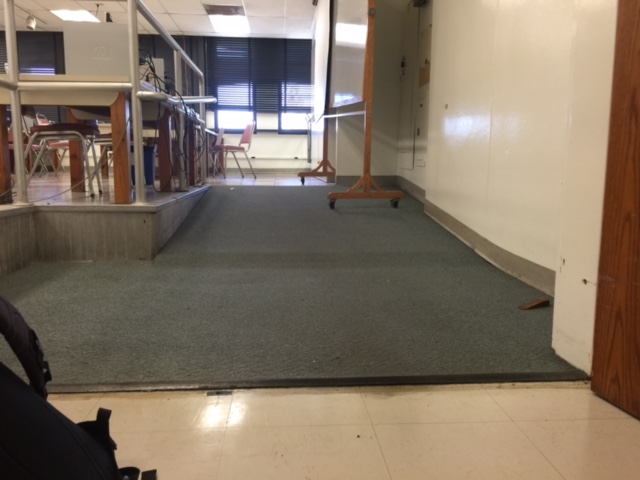
 Figure 4: Berber Carpet


