Spring 2016 A-TeChToP Preliminary Design Documentation
By: Cody Dunn (Project Manager)
Central Sensor Suite:
Omar Rojas (Systems Engineer)
Stephen Cortez (Electronics Engineer) Read more
By: Cody Dunn (Project Manager)
Central Sensor Suite:
Omar Rojas (Systems Engineer)
Stephen Cortez (Electronics Engineer) Read more
By Mikhael Semaan (Project Manager), with contribution from
Jeremy Seiden (Systems and Subsystems),
Chelsea Mediavilla (Electronics and Control), and
Eric Hanna (Design and Manufacturing).
We review the preliminary design, including program and project objectives, requirements, system and subsystem design, work breakdown, and preliminary project schedule and plan.

Velociraptor Team:
Khoi Vu (Project Manager)
Camilla Jensen (Systems Engineer)
Ashlee Chang(Electronics & Control Engineer)
Mingyu Seo (Design & Manufacturing Engineer)
Table of Contents
By: PM Khoi Vu
The Spring 2015 Velociraptor biped was inspired by the robot Titrus-III; it was designed and created by Tokyo Institute of Technology. The purpose of this project is to design a Tyrannosaurus class biped robot to be used as a toy. The mission profile is to demonstrate the feasibility of the dinosaur biped as toy product. The objective of this project focuses on a toy with the ability to detect and avoid obstacles. The Velociraptor will be controlled by establishing a communication with the Arxterra Android application.
The requirements are divided into two categories, program and project. The program requirements are general requirements that the robot must fulfill, whereas project requirements are more specific to the appearance and ability of the robot. To ensure the success of this project, these requirements were set based on the customer’s objectives and mission profile.
By: S&T Camilla Jensen
By: PM Khoi Vu, E&C Ashlee Chang
There are many different attributes to focus on in design such as material, input devices, color, size, shape, taste, texture, hardness, and odor. Some of the few focused on for the velociraptor are listed below.
By: S&T Camilla Jensen
Power
The Velociraptor will have power supplied from a portable source, such as a battery so that it can be controlled remotely from the Arxterra application on an Android phone.
Servos
As the mission objective states that the Velociraptor will be a biped robot so the research from last semester’s MicroBiped using the servos as motors to perform walking proved to be the best option. A study was conducted to compare the different servo options for the Velociraptor (servo trade-off study). Last semester’s MicroBiped failed to successfully walk; therefore, to improve on this feature for the Velociraptor, 8-10 servos are to be used to provide enough torque to conform to The Level 1 Project Requirements. Complying with The Level 1 Program Requirement #2 and taking into account the cost-effectiveness aspect, the trade-off study will be conducted to determine which servo to buy that will keep the cost of the servos within the program’s budget of $400 dollars.
Size
To follow the Level 1 Project Requirements, the Velociraptor will be a toy robot of no more than the size of last semester’s MicroBiped and Titrus-III, roughly measured, 40cm x 13cm x 11cm.
Sensors
To comply with the Level 1 requirement #8, Ultrasonic sensors will be implemented for obstacle detection and avoidance as described in the mission. To control the balance of the Velociraptor when walking up inclines, another sensor will be implemented to determine position and orientation. A research of last semester’s choice of a gyroscope for its MicroBiped followed and a trade-off study (Link to Accelerometer vs. Gyroscope trade-off study) of the Accelerometer vs. Gyroscope, the accelerometer qualified as the better option for the Velociraptor to measure and relay orientation information of the Velociraptor. The system will collect real time data from the sensors and send them to a third party application, the Arxterra app, which will be controlled by the user.
Communication
To control the Velociraptor wirelessly, an Android phone paired with the Arxterra Application will receive sensor data via a Bluetooth device and allow for remote control. Arxterra is a telerobotics company developing open source robots that can control the robots from anywhere with cell phone coverage. The Arxterra Control Panel allows for easy integration of a user interface on the Arxterra App to be controlled on the Android phone and thus fulfilling the Level 1 requirement #9.
Materials
The material of the Velociraptor must be strong and durable. A suitable material for this will be aluminum. Aluminum is both lightweight and sturdy and will be able to carry the added weight of the extra 2-4 servos that are to be implemented to the Velociraptor. Hollowing body parts on the CNC machine to manufacture a frame-like chassis will lower the weight while also reducing the costs of material. A study using SolidWorks will be conducted to verify the strength of aluminum to carry the weight of robot without bending or cracking.
Battery
The battery for the Velociraptor will need to provide power for 8 servos and the microcomputer. It will need to be rechargeable and more cost efficient in the longer run. The battery should provide power for the Velociraptor to complete the mission in one trial and thus when decided what servos to use, the estimated time the robot will spend to complete the mission will be calculated. For the Velociraptor to statically walk, the battery should have a high discharge rate in order to deliver a large amount of power at one time for performing one step. For safety requirement, the maximum safe continuous discharge rate must be greater than the maximum current drawn from the servos and electronics board.
By: S&T Camilla Jensen, E&C Ashlee Chang

Elementary approach to mapping the system
In order to accommodate all the requirements of the customer, the velociraptor will have many input sensors and output actuators in place. Based on the information obtained from the sensors, the velociraptor will in turn perform an action and output the information to the actuators. A list of all components is listed: sensors (ultrasonic sensor, accelerometer, Bluetooth), communication (Bluetooth in an Android), microcontroller, power source (battery), and actuators (servos). Below maps out a more complex block diagram. More details about the pin locations are shown in the Fritzing diagram.

Interface Definitions:

Table 1: Pin connections for Arduino Microcontroller
Table 1 shows the total number of ports on the ATmeg32U4 board in combination with the Arduino pins. To estimate the pins needed to connect the components to control the Velociraptor a comparison with table 2 has been made to eliminate the leftover pins.

Table 2: Pin connections for components of Velociraptor
System Resource Map:
By: Camilla Jensen (Systems Engineer)

Table 1 shows the outcome of the comparison of table 1 and table 2 from the Interface Matrix. E&C engineer Ashley Chang performed a test of the of servo communication with the microcontroller and the test proved that the need for a servo driver as last semester used to communicate with the servos for the PMW signal is unnecessary as the servos are compatible to communicate with the microcontroller through digital I/O pins as well. Therefore, the servos for this semester Velociraptor are connected to the digital output pins 2-9 as shown in Table 1.
Fritzing Diagram:
By: M&D Mingyu Seo

By: M&D Mingyu Seo
Introduction
For the velociraptor biped, the design must not only be able to provide a new solution to incorporate biped features but also possible use for a future toy design. This design will demonstrate the feasibility of the dinosaur biped as a toy product and allow future semesters the flexibility of upgrading and reworking the design to be more interactive between the user and the robot. The design of the velociraptor biped will be based on structures designed by Titrus-III, created by Tokyo Institute of Technology, while incorporating new features such as ultrasonic sensor and accelerometer sensor.
Preliminary Sketches
Using the Titrus-III model as a reference, Figure 1 shows the drawing if preliminary sketches by roughly defining the size of each component, which will adhere to the Velociraptor standards as prescribed in our level 1 project requirements. One of the parts I’ve emphasized was to keep the base of the foot to be parallel to the body to ensure stability.
 Figure 1
Figure 2. shows the components that make up for the joint. The joint is made up of 8 different components, which includes a frame for the knee, 2 connectors from knee to ankle, 2 connectors for the 2 servos we’ll be using each leg, and 1 connector from knee to the body of the velociraptor to keep the legs stable and parallel to the body when we perform static and dynamic walking.

Figure 2
By: E&C Ashlee Chang, M&D Mingyu Seo
Associated task description: Walking on two different terrains–linoleum and carpet.
Associated task description: Walking over a 0.5 cm rubber divider
Associated task description: Object detection
Associated task description: Velociraptor must turn in the case of an object being in its path
Associated task description: The velociraptor must be controlled wirelessly
Associated task description: A phone app will be used to remotely control the velociraptor
Associated task description: Use of servos to move the head and tail to balance while walking
Associated task description: Dynamic walking
Associated task description: Product category is a toy and must be safe for certain age groups
By:
Peiyuan Xu (Project Manager)
Xiong Lee (Mission, System and Test Engineer)
Juan Acosta (MCU Subsystem and Control Firmware)
Tuong Vu (Sensors, Actuators and Power)
Lindsay Levanas (Design and Manufacturing)
Table of Contents
Analysis of Past Level 1 Requirements
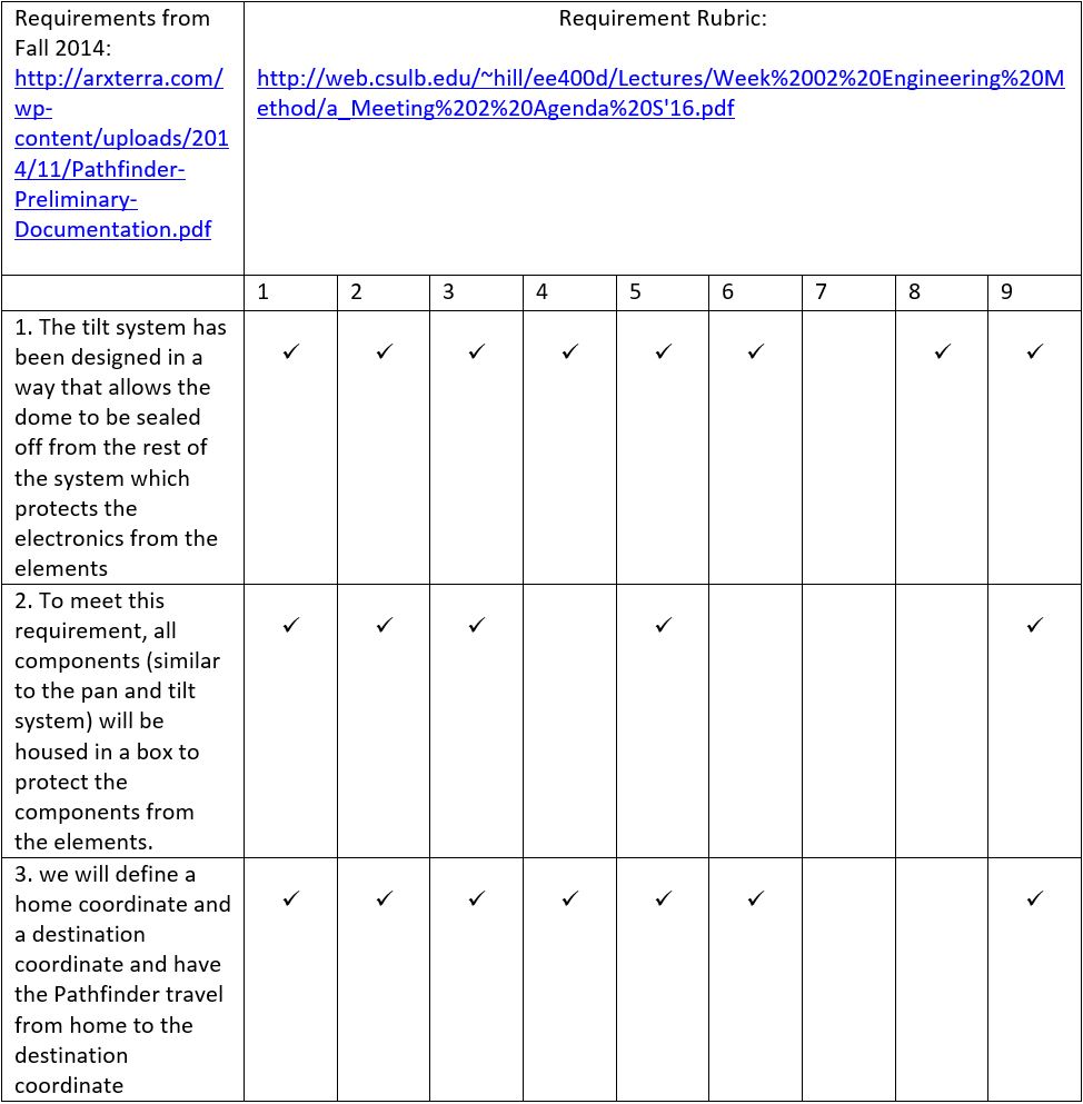
Requirement Evaluation Rubric:
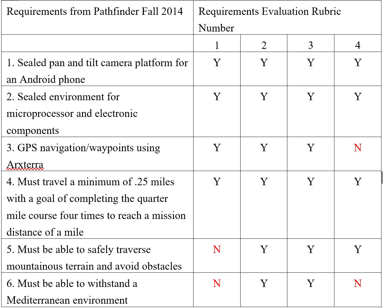
The Group clearly stated the issue that automation industry meets and the needs for them to develop autonomous and self-Sufficient machines. The project objective was generated properly based on the customer’s expectation. However, on the requirements level, the group did not use enough quantitative, verifiable, and realizable thinking to write their level 1 requirements. For number 5 and 6 of their requirements, there was no quantitative variables that can be measured or proved to meet their requirements. Those requirements could be improved by mentioning more details of the environment such as quantitative temperature, wind speed, dust level, etc. In addition, the word “shall” should be used instead of “must” in those two requirements. Some of the requirements are lack of source links for us to research them in details. Their preliminary research posted nearly at the end of the semester and included level 2 requirements as well. Their final documentation and preliminary research had very much the same content. Their final video documentation was made properly as it contains their design of work and testing activities. But one thing I noticed that for the video documentation, they did not include the final testing of Pathfinder running in the Mediterranean environment which was one of their requirements.
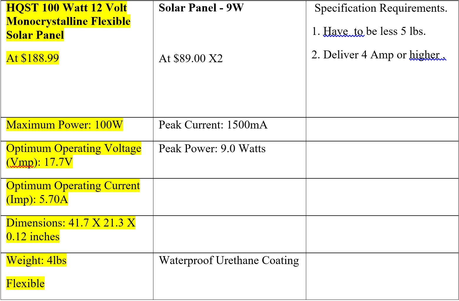
Many changes will happens on the Pathfinder this semester. These include using solar panels to charge the batteries and also google Tango tablet will be used to navigate pathfinder instead of using GPS navigation/waypoints. Therefore our requirements will various from Fall 2014 semester. These may include:
For our preliminary budget, we will assume to spend up to $150 on appropriate solar panels that have enough power to charge batteries in short amount of time. The Google Tango can be borrowed from the president form CSULB HKN society. Other mechanical parts and electronics can cost up to $150. Total cost will be limited to $300 negotiable.
http://web.csulb.edu/depts/enrollment/registration/final_exam/spring_chart.html
By Xiong Lee (Mission, System, Tests)
Overall, their level 2 requirements were very good. They gave good documentations of what they did for their level two requirements. For example, how they designed their pan and tilt system for their android phone. There were things that could have been better documented. They didn’t list sources where they got the specs of their batteries, shield, arduino from.
Microprocessor and Arduino:
| Microcontroller | ATmega2560 |
| Operating Voltage | 5V |
| Input Voltage (recommended) | 7-12V |
| Input Voltage (limits) | 6-20V |
| Digital I/O Pins | 54 (of which 15 provide PWM output) |
| Analog Input Pins | 16 |
| DC Current per I/O Pin | 40 mA |
| DC Current for 3.3V Pin | 50 mA |
| Flash Memory | 256 KB of which 8 KB used by bootloader |
| SRAM | 8 KB |
| EEPROM | 4 KB |
| Clock Speed | 16 MHz |
| USB Host Chip | MAX3421E |
| Length | 101.52 mm |
| Width | 53.3 mm |
| Weight | 36 g |
https://www.arduino.cc/en/Main/ArduinoBoardMegaADK
Some proposed level two requirements based on our level one requirement:
Their testing of their products can be found here. They tested their GPS, Communication Bluetooth, batteries, weight and height clearance and their coding. Most of these testing had good documentations of what they did in the experiment. One thing was where they got their sources material from. They didn’t show sources to how the battery should be tested or etc…
http://arxterra.com/pathfinder-axterra-gps-communication-part-three/
http://arxterra.com/pathfinder-code-flowcharts/
http://arxterra.com/pathfinder-arxterra-communication-commands/
http://arxterra.com/pathfinder-pin-interface/
Their flowcharts and block diagrams were good. They specified everything they had on the pathfinder from their three batteries to the Bluetooth and GPS. For our system diagram, we’ll have to add the tablet and solar panel into the diagram. Our flowcharts will change because we have a different mission than what they have from the customer.
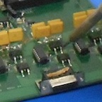
Their use of a separate pcb to store the sensors, regulators, Bluetooth, etc… (Shown above in the system block diagram) helped them make their electronics and wiring cleaner. Their diagram showed how each product interfaced with each other. On our project, we’ll have to make our Google Tango tablet communicate with the Arduino on the pathfinder. We’ll also have to use the arduino to communicate with the solar panel so it can charge up the batteries of the system and motors.
Sensors, Actuators and Power
By: Tuong Vu
E&C Division
Servos :
Motors :
Battery.
Solar panel.
Buck regulator.
Charge/ discharge voltage regulator
Servos:
Motors:
Solar Panel.
Buck regulator:
Charge /discharge voltage regulator.
Battery
By: Juan Acosta
https://www.arxterra.com/rosco-and-pathfinder-arduino-code-versions-available/
https://github.com/arxterra/Pathfinder_Rover
http://arxterra.com/news-and-events/members/pathfinder-4/
The previous design of the Pathfinder used modified Servos for pan and tilt control of the phone. Instead of modifying an existing servo, they should have bought an inexpensive servo with no limitations on turning radius to solve this minor issue. This could have saved a little time and helped moved the project along by allowing more time to focus in other areas that were having major issues.
The main loop program flow for the previous Pathfinder project was successful in drawing out the tasks of the Pathfinder. They implemented simple true or false checks in order decide what action the Pathfinder should take next. This looks like a fast, simple and effective way of implementing the main loop program.
The previous design’s code flowcharts were a good starting point for their final software implementation. They clearly defined sensor input triggers and appropriate decisions based on those inputs. They did not mention if their decisions or actions were a result of Level1 requirements, but it looks like they carefully planned out all of the necessary decisions the Pathfinder would have to make based on the terrain and lap objectives.
For the MCU Subsystem and Control Firmware section of the Electronics & Control Division, I will have to: 1) write the firmware required to translate commands from the tango tablet into control signals to the motors and servos in order to move the Pathfinder or move the pan and tilt field of view for the Google Tango, 2) Read sensors such as wheel decoders and translate into data bytes for calculating speed and distance to travel, and 3) implement control algorithms for controlling the charging of the Pathfinder’s solar panel charging network.
In order to code for tasks 1 and 2, I will reference and then modify the Pathfinder Code Flowcharts created by a past semester’s blog posting. I will also reference previously uploaded code for the Pathfinder that is available on GitHub from the Arxterra website.
Lastly, in order to code the algorithms for measuring and controlling the charge of the battery via solar panels, I will have to do further research on safe charging procedures and requirements and battery protection. I hope to have a scaled version of the Pathfinder available for prototyping and testing of the control firmware before final implementation to the final design.
Based on previous code for the Pathfinder, some of the level 2 requirements will have to be modified or deleted. For Example, our design will incorporate the Google Tango so there will be no need for obstacle avoidance measures and sensors since our design won’t be autonomous as it was defined as a level 1 requirement that the Google Tango is to act as a remote control with field of view. Examples of some of the code that I will have to tailor to our design are the programs written to measure battery consumption, drive the motors, and drive the servos. Programs that I might have to develop are charge controlling algorithms to safely charge and discharge the Pathfinder’s battery cells for optimal usage as define by the level 1 requirement needing the Pathfinder to be able to spend a day exploring the Amboy Crater.
A few of the programs previously written for the Pathfinder have not been uploaded or tested, so it will be crucial for me to start testing and debugging algorithms that are available on GitHub to determine which ones are viable and which ones I will need to code myself. It will be important for me to have working knowledge of how to code and upload programs onto the Arduino Board, so I will attend any and every training session that the Electronics & Control Division Manager hosts in order to continue to move this project forward. The Previous Design utilized an Arduino Mega so I will have to research on similarities and differences between the Uno and the Mega and see which one would be a better level 2 requirement solution.
By: Lindsay Levanas
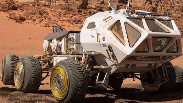
During the fall of 2014, the first Arxterra Pathfinder project was outlined and implemented. The basic concept was to mirror Mars rovers, both in their basic construction and autonomous ability. To this end, requirements were created to help guide the original designers in building a simplified Earth base model. Now, during the spring of 2016, a new group of engineers will work together to build upon the previous Arxterra Pathfinder project to bring it closer to the rovers that have been sent to Mars. Following below is a review centered on the design and manufacturing elements of Pathfinder’s requirements as discussed in its original documentation. The review will consist of the evaluation and modification of previous requirements to encompass the new project goals to implement Google Tango and solar panels in the current Pathfinder model, as well as new requirements where necessary.
Pathfinder’s first original requirement was to utilize a sealed pan and tilt camera platform for an Android phone.1 Using the dimensions of the Pathfinder’s base and the field of view measurement calculations from the Android phone’s camera, a design was selected and modeled.5 While the measurement requirements are quantitative, verifiable and realizable, the resulting 3D model of the pan and tilt platform is not, as not all measurement dimensions are given. The dimension of each piece is not defined, and so a working 3D model of this platform cannot be duplicated. Located at the subsystem level (level 2), this 3D modeling requirement is linked to the project level (level 1) requirement for a sealed pan and tilt camera platform for an Android phone.6 With the proper measurements, this 3D model would move the design process forward, as materials for the parts could then be selected (by trade-off study, though this process is currently missing from Pathfinder’s documentation) and the final product could be constructed on Pathfinder’s base.
For the spring 2016 Pathfinder project, the above requirement and it’s subsequent requirements, trade-off studies, and measurement calculation process will not change much accept to accommodate a Google Tango tablet as the camera, instead of an Android phone. Also, as the 3D model of the pan and tilt platform is not clearly defined, a trade-off study of different designs and their measurements will be done.
Lastly, a new sublevel requirement will be added to account for temperature control of the sealed pan and tilt platform.
Another of Pathfinder’s project level (level 1) requirements was to create a sealed environment for the microprocessor and electronic components.2 Therefore a subsystem (level 2) requirement to 3D model the sealed environment was created.8 However, unlike the pan and tilt platform, the sealed environment for the electronics wasn’t modeled alone. Instead, both sealed environments were 3D modeled together with the body of Pathfinder to create the preliminary design requirement.7 As this design features 3D modeled pictures only, it is qualitative and not verifiable or realizable. Also, while the 3D modeled sealed environment for the electronics is linked to one of the project requirements, the Pathfinder 3D model as a whole is not. Therefore, it should be worded such that it encompasses the other two sealed environment requirements and should replace them as a project level (level 1) requirement. The sealed pan and tilt camera platform for an Android phone requirement, and the sealed environment for the microprocessor and electronic components requirement should then be redefined as subsystem (level 2) requirements so that the link back to the project level (level 1) requirements is easily traceable. Placed in this order, the preliminary design requirement would move the design forward, as then the subsystem requirements for the sealed environments would naturally follow. Finally, note that there are no links to source material and that no equations are used to calculate the initial set up for the preliminary design requirement.7
Similar to the 3D simulated sealed pan and tilt camera platform for an Android phone requirement, the 3D simulated preliminary design requirement is lacking in measurements and design trade-off studies. However, as the spring 2016 Pathfinder project will incorporate a Google Tango tablet and solar panels in its design, different structural trade-off studies then those mentioned to be missing will be conducted to account for the new design conditions.
Lastly, a new sublevel requirement will be added to account for temperature control of the sealed environment for the microprocessor and electronic components.
Based on the original documentation, the 3D printing of the sealed pan and tilt camera platform for an Android phone is a subsystem (level 2) requirement.9 As measurements are not given, the 3D printer requirement is qualitative only, and not verifiable or realizable. Had this requirement been listed under the project level (level 1) requirement of making the sealed pan and tilt camera platform for an Android phone, it would have been a subsystem (level 2) requirement, but it was not. 3D printing was however mentioned under the project level (level 1) requirement to make a sealed environment for the microprocessor and electronic components,8 but then there is no documentation on that manufacturing process. Both of the project level (level 1) requirements mentioned should contain 3D printing as a subsystem (level 2) requirement to help link the two levels together. No links to source material are mentioned, though one about the quality expectations of 3D printers would help. Such a source would allow for a more realistic and detailed requirement. Providing the quality of the 3D printed sealed pan and tilt camera platform for an Android phone is high, this requirement moves the design forward in that it may now be integrated onto the body of Pathfinder. Also, although none are mentioned, this requirement is based on the 3D simulation’s measurements and dimensions.
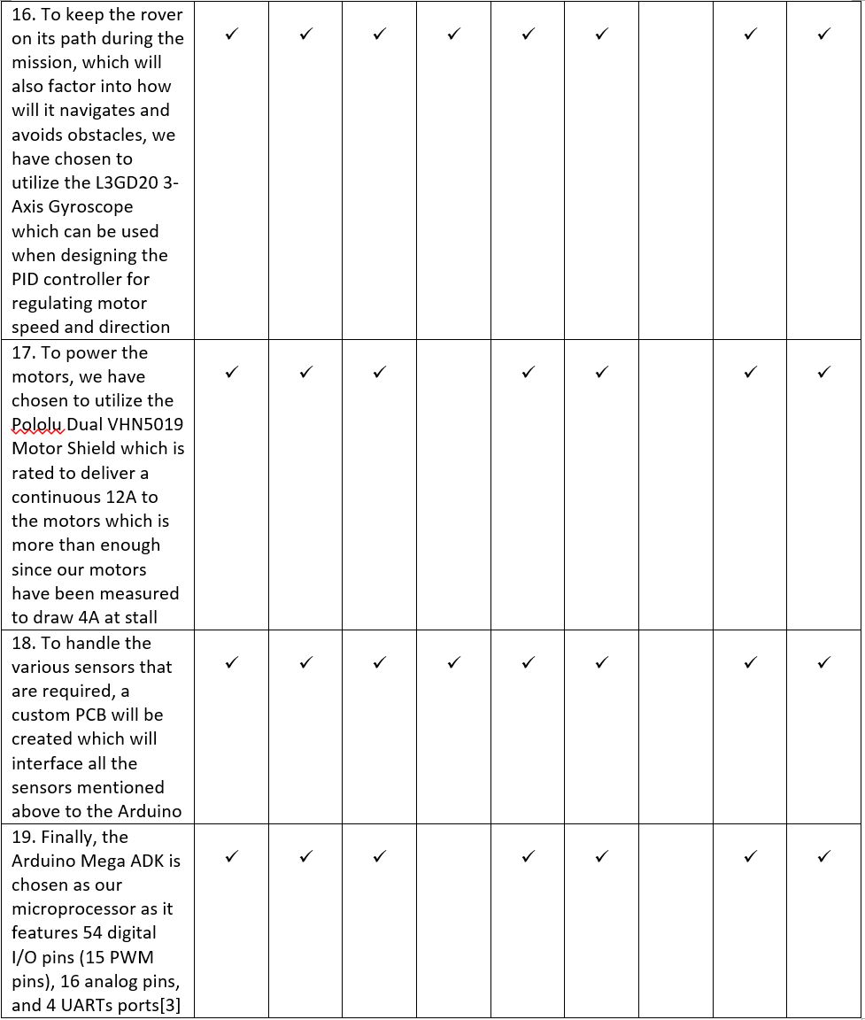
As there is a project level (level 1) requirement for Pathfinder to safely traverse mountainous terrain and avoid obstacles, it follows that there is a subsystem (level 2) custom PCB Design to limit the amount of wires in the open.10, 11 Though a qualitative requirement, it is still both verifiable and realizable. No links to source material is listed, however there is both a picture and pin assignment chart included in the document, making it possible to replicate and verify the PCB design requirement.12 Slimming the electronic components on to a PCB moves the design forward to meet its project (level 1) requirement of safely traversing mountainous terrain and avoiding obstacles.3
For the spring 2016 Pathfinder project Google Tango will be used instead of the Android phone’s camera, GPS system, and sensors. In addition, Solar panels will be used to charge the batteries, therefore powering Pathfinder’s system. Both of these features will be implemented into the PCB while their previous counterparts are removed. As such, a different PCB board will be used based off of the new schematic that the electronics and control engineer (PCB Design) will design.
Pathfinder’s design and manufacturing will include 3D simulated models of Pathfinder as a whole, of the sealed pan and tilt camera platform for a Google Tango tablet, and of the sealed environment for the microprocessor and electronic components. From these models, parts may be either 3D printed or purchased. Finally, a custom PCB run by solar panels will be assembled.


By:
Luis Valdivia (Project Manager)
Anthony Becerril (Mission, systems and test)
Juan Mendez (Design and manufacturing)
Kevin Nguyen (Electronics and Controls)
Table of Contents:
1. Project Manager Research:
Project Level 1 requirements:
Overview/Purpose: Highlight baseline qualitative requirements for the overall mission.
Mission Objective(s) from previous semesters: Produce aircraft that performs flight path set by the customer. The aircraft must also maintain stability as it travels its flight path. To meet aesthetic requirements set by the customer, the vehicle must resemble a UFO or the Millennium Falcon as well as producing a light show
Mission requirements from previous semesters:
Mishaps:
Proposed solution for Spring 2016:
Project Budget:
Overview/Purpose: Keep track of budget to avoid overspending.
Budget based on previous semesters:
Mishap: None. Requirements were met by remaining under set budget.
Proposed solution(s) for Spring 2016:
Project Schedule:
Overview/Purpose: Set a work schedule to follow on a weekly basis throughout the semester..
Project schedule based on previous semesters.
Proposed solution(s) for Spring 2016:
EVALUATION RUBRIC
Y= Yes
N= No
X= No answer needed
| Level 1 Requirements based from previous semesters | 1 | 2 | 3 | 4 | 5 | 6 | 7 | 8 | 9 |
| Must complete the project before end of semester. | Y | Y | N | Y | N | N | X | Y | X |
| Will follow regulations and policies for the FAA, UAS, & COE. | Y | Y | Y | Y | N | N | X | Y | X |
| Must not exceed budget. (estimated $400 from last semester) | Y | Y | N | N | N | Y | X | Y | X |
| Aircraft will maintain stable altitude while completing course. | Y | Y | Y | Y | Y | N | X | Y | X |
| Remote control aircraft and display light show. | Y | Y | Y | N | N | N | X | N | X |
| Meet aesthetic requirement set by the customer. | Y | Y | N | N | Y | N | X | Y | X |
Works cited:
2. Mission, Systems and Testing Research:
LEVEL 2 REQUIREMENTS:
Overview/Purpose: Detail level 2 requirements in alignments with level 1 requirements made to complete mission
Level 2 Requirements from previous semesters:
Mishaps: Stable flight has yet to be achieved with certain requirements never initiated (landing gear, flight, fire protection,…)
Proposed Spring 2016 Solution: revise level 2 requirements and consider new ones if new level 1 requirements are made
DIGITAL SIGNAL CANCELLATION:
Overview/Purpose: Implementation of signal cancellation from a digital approach, specifically by inverting the signal
Digital Signal Cancellation from previous semesters:
Mishaps: Cancellation failed via audio recordings
Proposed Spring 2016 Solution: Discuss with team if further work is necessary; If approved look into researching noise cancellation for aircrafts
NEOPIXEL LED LIGHT SHOW:
Overview/Purpose: A lightshow on the Adafruit NeoPixel Ring controlled with a microcontroller, bluetooth module, and app
NeoPixel LED Light Show from previous semesters:
Mishaps: None; successful creation of programmable LED light show; tape lights considered and never revisited
Proposed Spring 2016 Solution: Consider investigation light functions to display battery life
BLUETOOTH INTERFACE TO ARXTERRA APPLICATION:
Overview/Purpose: how to use bluetooth to control the UFO via phone
Bluetooth Interface from previous semesters:
Mishaps: None; successful bluetooth integration
Proposed Spring 2016 Solution: Consider using, editing, or remaking method of controlling the UFO
ESC CURRENT DRAW TEST:
Overview/Purpose: Calculations of current draw from EDFs for overall power consideration
ESC Current Draw Test from previous semesters:
Mishaps: Upon shorting, an upgrade was made to replace the ESC for short time to maximum throttle
Proposed Spring 2016 Solution: Consider retesting to check for functionality
EDFs (ELECTRIC DUCTED FANS):
Overview/Purpose: Overview on Electric Ducted Fans (EDFs) bought and installed on the UFO.
EDFs work from previous semesters:
Mishaps:
Proposed Spring 2016 Solution: Retake tests and specifications
WIRELESS REMOTE COMMUNICATION USING XBEE RADIOS:
Overview/Purpose: wireless communication between the UFO and the user via an XBee Radio
Wireless Remote Communications from previous semesters:
Proposed Spring 2016 Solution:
UFO SYSTEM BLOCK DIAGRAM AND ELECTRICAL SCHEMATIC:
Overview/Purpose: Provided system block diagram and electrical interface diagram of UFO
System Block Diagram and Electrical Schematics from previous semesters:
Mishaps: upon visual inspection, there is room for improvement
Proposed Spring 2016 Solution: Update with any changes made this semester
EVALUATION RUBRIC
Y= Yes
N= No
X= No answer needed
| Level 2 Requirements based from previous semesters | 1 | 2 | 3 | 4 | 5 | 6 | 7 | 8 | 9 |
| UFO will be created with quadcopter frame and electric ducted fans | Y | Y | Y | N | Y | N | X | Y | X |
| UFO will have specific diameter and weight | Y | Y | N | N | N | N | X | Y | X |
| UFO will be protected against fires | N | Y | Y | Y | Y | N | X | Y | X |
| UFO will utilize LED ring for light show | Y | Y | Y | N | Y | Y | X | Y | X |
| UFO will use Electronic Speed Controllers (ESC) | Y | Y | Y | N | Y | N | X | Y | X |
| UFO will use a microcontroller and flight controller as control system | Y | Y | Y | N | Y | N | X | Y | X |
| UFO will be able to communicate wirelessly via Arxterra application and bluetooth module with specific range | Y | Y | Y | N | Y | N | X | Y | X |
| UFO will be equipped with landing gear | Y | Y | Y | N | Y | N | X | Y | X |
| UFO will have shell to give likeliness to UFO | Y | Y | Y | N | Y | N | X | Y | X |
| UFO to achieve flight with specific elevation and speed | Y | Y | Y | Y | Y | N | X | N | X |
| UFO to provide enough power for flight around classroom | Y | Y | Y | Y | Y | N | X | N | X |
Works cited:
3. Design and Manufacturing Research:
YAW Problem:
Overview/Purpose: The reaction wheels were to be fabricated in order for fix the Yaw problem
Research on previous semester work:
Mishaps
Proposed Solution for Spring 2016:
UFO’s shell production:
Overview/Purpose: The purpose of the shell was to give the UFO a look that resembled the craft from the movie “ The day the Earth stood still”
Research on previous semester work:
Mishaps
Proposed Solution for Spring 2016:
UFO’s PCB:
Overview/Purpose: To create a PCB and a surface mount device used to control the UFO and LED light show.
Research on previous semester work:
Mishaps
Proposed Solution for Spring 2016: This semester, we will be ensuring that the PCB has enough space to make sure that current flows through smoothly. We will also be working on Soldering on the components properly. One thing that was notices was that some wires were not soldered on properly, therefore breaking off and possibly not making a proper connection. We will also be insulating out wire components in order to not have a bundle of wires nested around.
Carbon Fiber Body:
Overview/Purpose: To build a carbon fiber body for the UFO using the design from the previous semester.
Research on previous semester work:
Mishaps
Proposed Solution for Spring 2016: Not much modifications will be done to the carbon fiber body. The only improvement we are proposing is to add on a case for the battery since it is unprotected at the moment and want to protect it from getting damaged. Along with making a case we want to add on landing legs to it so the UFO will land safely instead of landing on the battery itself.
4. Electronics and Controls Research:
YAW Control:
Overview/Purpose: Prevent UFO from spinning uncontrollably by stabilizing the yaw rotation.
Yaw Control from previous semester:
Mishaps:
Proposed Solution for Spring 2016:
PID Tuning:
Overview/Purpose: Determine the best coefficient values for our PID controller so that we would achieve the most efficient stabilizing effect.
PID tuning from Previous Semester:
Mishaps:
Proposed Solution for Spring 2016:
Analog Noise Cancellation:
Overview/Purpose: Use analog components to design a noise cancelling circuit to reduce the noise of the UFO.
Analog Noise Cancellation from Previous Semester:
Mishaps:
Proposed Solution for Spring 2016:
Experiment: Battery Discharge Characteristics and Voltage Monitor:
Overview/Purpose:
Battery Discharge Characteristics and Voltage Monitor from previous Semester:
Mishaps:
Proposed Solution for Spring 2016:
Multiwii ESC and Receiver Connections:
Overview/Purpose:
Multiwii ESC and Receiver Connections from previous Semester:
Mishaps:
Proposed Solution for Spring 2016:
PCB Design – Battery Protection Circuit:
Overview/Purpose:
Battery Protection Circuit from previous Semester:
Mishaps:
Proposed Solution for Spring 2016:
PID Control and Tuning:
Overview/Purpose:
PID Control and Tuning from previous Semester:
Mishaps:
Proposed Solution for Spring 2016:
Trade-Off Study: Battery
Overview/Purpose:
Battery Trade-Offs from previous Semester:
Mishaps:
Proposed Solution for Spring 2016:
Quadcopter PID Control:
Overview/Purpose:
PID Control from previous Semester:
Mishaps:
Proposed Solution for Spring 2016:
Trade-Off Study: Motor Battery Selection
Overview/Purpose:
Battery Trade-Offs from previous Semester:
Mishaps:
Proposed Solution for Spring 2016:
Final Controls Update:
Overview/Purpose:
Final Controls Update from previous Semester:
Mishaps:
Proposed Solution for Spring 2016:
Experiment: Prototype Test
Overview/Purpose:
Prototype Test from previous Semester:
5. Creativity Assignment:
Random Nouns Generated:
How do we protect vehicle from crash landing damage/ hurting people?
What can we do to control the Yaw rotation?
By: Bao Loc Doan (Project Manager)
Christine Vu (Systems Engineer)
Henry Nguyen (Electronics Engineer)
Nasser Alsharafi (Manufacturing)
Project Manager Research
Bao Loc Doan (Project Manager)
Mission Objective
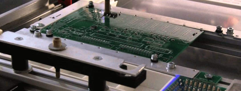
When humans manually pick and place surface mount components onto a printed circuit board (PCB), there are problems with human accuracy and time efficiency. A pick and place surface mount device (SMD) is an automated device that can populate a printed circuit board (PCB) with surface mount components (resistors, capacitors, and IC chips) by referencing a Gerber file. The SMD pick and place machine will be able to pick the surface mount components up and place the components down at the correct location until the board is finished. The objective of this project is to create a pick and place SMD machine and the customer has expressed the desire to keep the overall budget of the project to be around $600.
Creativity
All creative ideas and brainstorming were done prior to establishing a firm base. You can read about our ideas given below in the link.
https://docs.google.com/presentation/d/1F_2NlVyMoYl47WXqDsclBF27teGJwjQjFWzvZX9yafo/edit?usp=sharing
Level 1 Requirements
To satisfy our gracious and generous customer, a list of requirements that our end product needs to meet were created. These requirements takes into account functionality, appearance, and price.
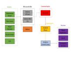
Work Breakdown Structure
The goal is to produce a working prototype by the end of the school semester (approximately 15 weeks). In order to meet that goal, a WBS (Work Breakdown Structure) needed to be created in order to allow group members to focus on their own specific divisions. The following graph is the WBS that I and our system engineer, Christine Vu, developed.
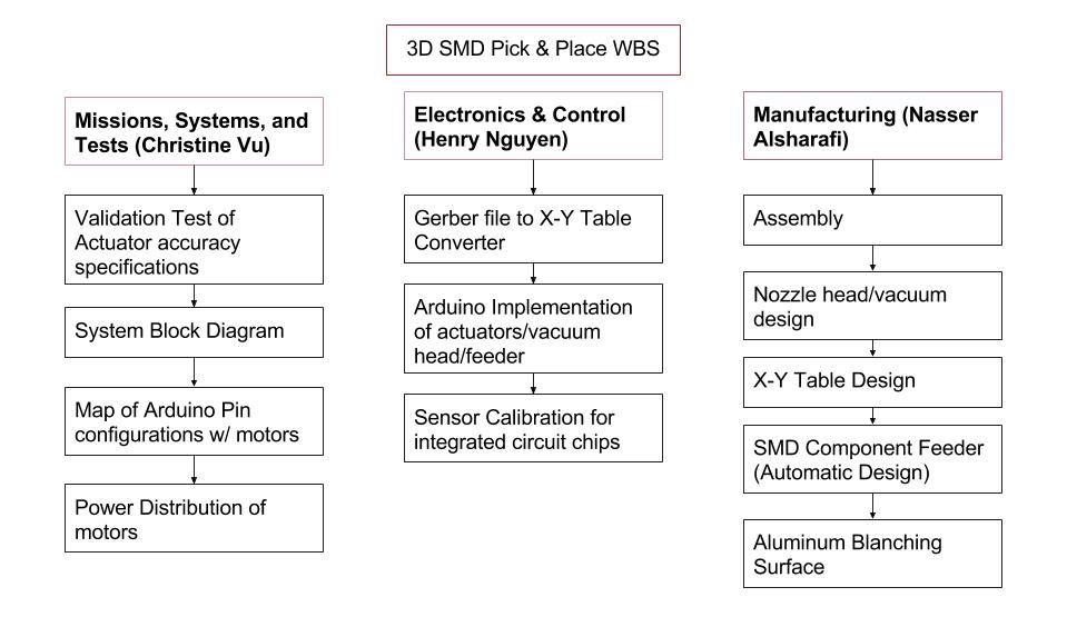
Figure 1 – Work Breakdown Structure
Product Breakdown Structure
Now that we’ve developed what our WBS is, the next step that we took was developing a PBS (Product Breakdown Structure). The PBS will allows us to map out the key components of our design.
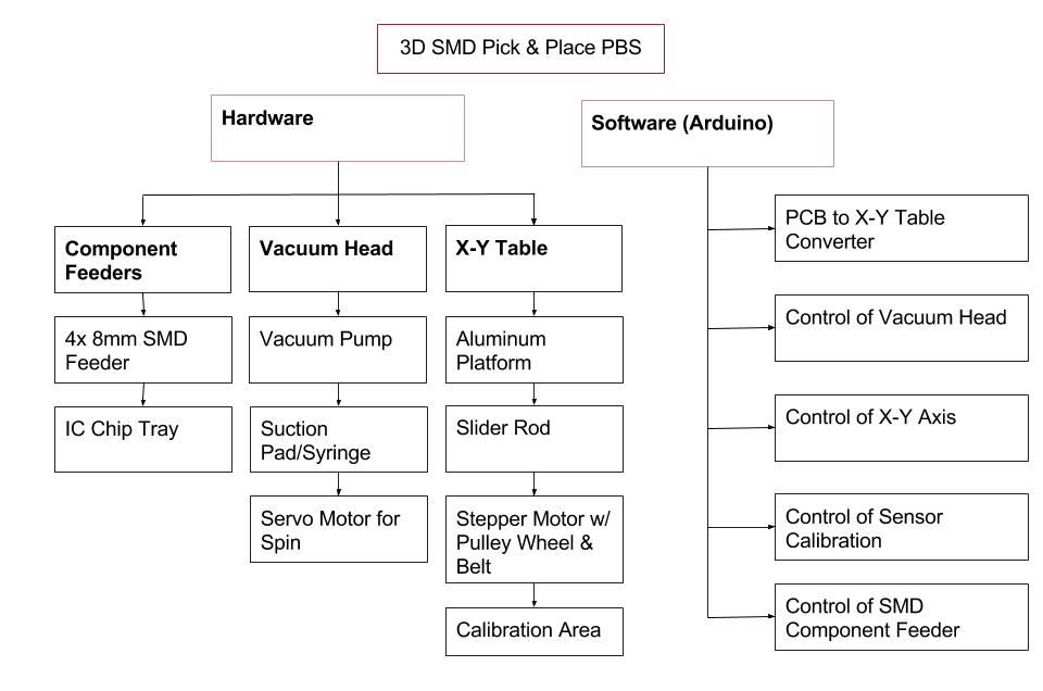
Figure 2 – Product Breakdown Structure
Budget
Our preliminary budget ended up being slightly under the budget given by our customer. The bulk of the price (~$300) will be from the XY plotter that will be purchased from Ebay. Outsource labor takes into account the costs that the machinist will charge for their services. This number is merely an estimation and the number was given to me by a connection that I have to a machinist that would be willing to work with us.
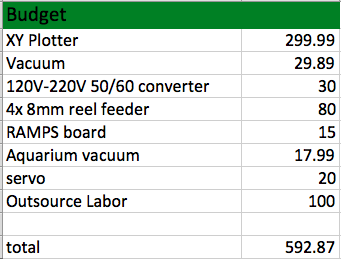
Figure 3 – Estimated Budget
Systems Engineer Research

Christine Vu (Systems Engineer)
As a systems engineer, one must consider the components that make up the project design to formulate requirements, functionality, and progress.
For the pick and place Surface Mount Device (SMD) machine, we had to include both the course’s requirements and requirements that will progress the design. In the requirements section, words like “shall”, “must”, and “will” are equivalent and are mandatory to move the design forward. Words like “may” are suggestions that are optional to the design. It is also important to note that the table to hold PCB and the X-Y Table is used simultaneously and are equivalent. During the requirement-forming process, Henry Nguyen (Electronics) and I went over subsystem requirements while Bao Loc Doan (Project Manager) and I went over system requirements.
Level 2 System Requirements
Level 1 Requirements (L1):
Level 2 System Requirement (L2):
L2 -1 SMT component shall have a vibration displacement of less than 0.05 mm from its original spot during the entire operation. This requirement is so that the placement of the SMT components would prevent incrementing error.
1. The pick and place SMD machine shall be able to complete at least one PCB.
Level 2 System Requirement:
L2 – 2 Noise level of pick and place SMD machine during run-time shall be under 40 dB. This is a requirement so it would not disturb our customer.
Level 2 System Requirement:
L2 -3 Gerber file shall include at least one 0402 component. This is per requirement of great leader Hill.
Level 2 System Requirement:
L2 – 4 Pick and place SMD machine shall send zero error feedback.
Level 2 System Requirement:
L2 – 5 Pick and place SMD machine shall be clear of debris during operation, which would be pieces that are not part of the SMT components and are larger than the 402 metric component (0.4 mm x 0.2 mm, or 0.0157” x 0.0079”) and include wires. This requirement is so that when the PCB board is placed on a smooth surface, the application of solder paste will not be interfered.
Level 2 System Requirement:
L2 – 6 Pick and place SMD machine budget sheet shall be under $600.
Level 2 System Requirement:
L2 – 7 Pick and place SMD machine assembly schedule shall be submitted before February 11, 2016 at 11:59 PM.
Initial System Block Diagram
This block diagram was based on the Arxterra blog posts on RosCo from Fall 2015.It was discovered that the pick and place SMD machine can be operated using stepper motors as found through videos as shown on the MakeBlock X-Y Plotter. Another YouTube channel provided the entire run-through of the pick and place 3D SMD machine assembly, Scientist Razz. References of these videos are shown at the end of this blog post.
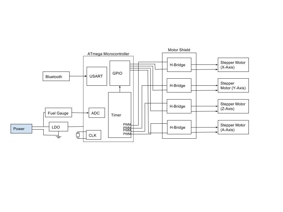
Figure 1. Initial System Block Diagram will control stepper motors.
System Interface Matrix
Pins on motor shield will be determined after further research on the benefits of buying a shield designing one.
| AVR | Arduino | Bluetooth |
| PD0 (RX) | Digital Pin 0 | TX |
| PD1 (TX) | Digital Pin 1 | RX |
| PD2 (INT0) | Digital Pin 2 | Motor Shield |
| PD3 (INT1) | Digital Pin 3 | H-Bridge |
| PD4 | Digital Pin 4 | H-Bridge |
| PD5 | Digital Pin 5 | H-Bridge |
| PD6 | Digital Pin 6 | H-Bridge |
| PD7 | Digital Pin 7 | 3D SMD |
| PB0 | Digital Pin 8 | X-Axis Stepper |
| PB1 | Digital Pin 9 | Y-Axis Stepper |
| PB2 | Digital Pin 10 | Z-Axis Stepper |
| PB3 | Digital Pin 11 | A-Axis Stepper |
| PB4 | Digital Pin 12 | |
| PB6 | Digital Pin 13 | |
| PC0 (ADC0) | Analog Pin 0 (Digital Pin 14) | |
| PC1 (ADC1) | Analog Pin 1 (Digital Pin 15) | |
| PC2 (ADC2) | Analog Pin 2 (Digital Pin 16) | |
| PC3 (ADC3) | Analog Pin 3 (Digital Pin 17) | |
| PC4 (ADC4) | Analog Pin 4 (Digital Pin 18) | |
| PC5 (ADC5) | Analog Pin 5 (Digital Pin 19) | |
| PC6 (ADC6) | RESET |
Figure 2. System Interface Matrix.
Validation Matrix:
| Validation Product | Activity | Objective | Method | Results |
|
Pick and place SMD Machine (Overall)
|
Customer will evaluate overall functionality and display of pick and place machine.
|
1.) Ensure that L2-1 and L2-2 are complied. 2.) Ensure that errors occurred during operation are picked up by machine per requirement L2-4. 3.) Ensure that machine is clean (clear of debris) per requirement L2-5. 3.) Evaluate overall budget costs per L2-6 and L2-24.
|
Test — Vibration displacement of SMT component must be measured using precision caliper with +/- 0.002 mm tolerance and presented to customer. | |
| Test — Measurement of noise level may be used by phone application. | ||||
| Analysis — To evaluate budget costs, documentation of purchased products and an excel sheet that includes all pick and place SMD machine components shall be submitted. | ||||
|
Gerber File
|
Customer will view specifications on Gerber file.
|
1.) Ensure L2-3, L2-20, and L2-21 are complied.
|
Analysis — Present Gerber file that would be used and include the smallest component 0402. | |
| Analysis — Create software to translate 4″ x 3.2″ Gerber schematic. | ||||
|
Stepper Motor Operation
|
Customer shall evaluate motor display and software. This is combined because software will control the stepper motors.
|
1.) Ensure that L2-19, L2-20, and L2-21 are complied.
|
Test — Stepper motor temperature may be measured on the outer surface. | |
| Test — Error must be recognized by the software. Errors may be orientation of integrated circuit chips. | ||||
|
3D Axis (X, Y, Z) Control
|
Customer will evaluate motion of motors.
|
1.) Ensure that L2-12, L2-13 are complied.
|
Test — Submit data of X- and Y-axes presenting a straight movement at an angle of 0 degrees with 2.5 degrees tolerance. | |
| Test — Verification of Z-axes must present a straight movement of 90 +/- 2.5 degrees using data | ||||
|
Nozzle
|
Customer will evaluate overall functionality of nozzle.
|
1.) Ensure that L2-14, L2-15, and L2-16 are complied.
|
Test — Rotation of nozzle shall be controlled to present the 180 degree rotation. | |
| Test — During vacuum system assembly, allow vacuum to be constantly on to hold the SMT component upwards and record time for 4 seconds. | ||||
| Belt Pulley | Customer will evaluate assembly of pulley. | 1.) Ensure that L2-18 is complied. | Test — Verification of belt width and pulley wheel width may be measured separately. | |
|
X-Y Table/Aluminum Surface
|
Customer will evaluate assembly of working surface area that is X-Y table/aluminum surface.
|
1.) Ensure that L2-8, L2-9, L2-10, L2-11, L2-21, L2-22, and L2-23 are complied.
|
Test — Measure table with an accurate, precise ruler to determine the dimensions of drilled holes and gap between clamp and PCB. | |
| Test — Table slanting can be checked using a leveler or the pythagorean theorem based on dimensions measured by an accurate, precise ruler. | ||||
| Wire Connections | Customer will evaluate quality of wire assembly. | 1.) Ensure that L2-17 is complied. | Test — Verify that quality of wire connections are not strained and have slack. |
Figure 3. Validation Matrix that covers Level 2 requirements. Deadline requirements were removed.
References:
MakeBlock X-Y Plotter:
http://www.makeblock.cc/xy-plotter-robot-kit/
Scientist Razz:
https://www.youtube.com/watch?v=1aL7_8LJ4E8
42BYG Stepper Motor Datasheet:
http://www.micropik.com/PDF/42byg[1].pdf
System Block Diagram & Systems Interface Matrix was based on RosCo’s Fall 2015 Design:
http://arxterra.com/rosco-updated-interface-definition-fall-2015/
Gerber File Processing:
https://www.ucamco.com/files/downloads/file/81/the_gerber_file_format_specification.pdf
Electronic Engineer Research
Henry Nguyen (Electronic Engineer)
As an electronics and control engineer, we must consider possible softwares and hardware that help move our 3D SMD design process forward. An electronic engineer is responsible for several sub divisions such as PCB Design, Sensors, Actuators, and Power, and MCU Subsystem and Control Firmware. Due to this project being the first iteration of its kind, a lot of R&D needed to be done. PCB Design will be put on hold until it is required in the design.
PCB Design:
Sensors, Actuators, and Power:
MCU Subsystem and Control Firmware
Subsystem Requirements
Level 1 Requirements (L1)
Level 2 Subsystem Requirements (L2 Sub):
Aluminum Table:
L2 – 8 Aluminum table will be 12.2047”x15.3543”(310mmx390mm) +/- 0.1” with small drilled holes in order to attach our clamping system.
L2 – 9 Table to hold PCB must be made of smooth aluminum with a clamping system which will be that holds the PCB with a gap of less than 0.5 mm.
L2 – 10 Table to hold PCB must be leveled at 0 +/- 2.5° with respect to the floor.
L2 – 11 Table to hold PCB shall be elevated to a minimum of 1” +/- 0.5” for solder paste heating.
Motor Movement:
L2 – 12 Motors moving in X-Y axes must be in a straight line at 0 +/- 2.5° with respect to the floor. The 2.5°tolerance is an estimate of human error. The physics of human error was only roughly studied due to the scope of this course.
L2 – 13 Motors moving in the Z-axis shall be moving in a straight line at 90 +/- 2.5° with respect to the floor.
L2 – 14 Motor that rotates the nozzle will be able to rotate 180° +/- 1°tolerance.
L2 – 15 At least one vacuum nozzle/head must be smaller than 0.4 mm x 0.2 mm (0.0157” x 0.0079”) by at least 0.1 mm +/- 0.05 mm. This size comes from the size of the smallest component, 0402 metric.
Vacuum System:
L2 – 16 Suction pressure of vacuum nozzle/head must be able to pick up integrated circuit components for at least 4 seconds.
L2 – 17 Wire connection configurations shall have a minimum bend radius of 11 times its diameter. This requirement is to relieve wire stress at rest and during operation.
L2 – 18 Width of belt to attach on pulley shall be less than 0.5 mm. This would help refrain the belt from slipping.
Level 2 Subsystem Requirement:
L2 – 19 Temperature of stepper motor shall be under 131° +/- 1°Fahrenheit. This requirement is based on the 42BYG stepper motor that was used for the MakeBlock X-Y Plotter.
Level 2 Subsystem Requirement:
L2 – 20 Software shall translate with zero error.
Level 2 Subsystem Requirement:
L2 – 21 Software shall be able to recognize and self-correct all mistakes.
Level 2 Subsystem Requirements:
L2 – 22 X-Y Table must be large enough to hold the standard free Eagle PCB dimensions (4” x 3.2”), with at least 5” around the PCB perimeter. The length of 5 inches is a safe measurement so that the PCB does not slip off during pick up.
L2 – 23 Size of working area shall be within 10”x12” with +/- 2” tolerance. This requirement is based on the X-Y Plotter from MakeBlock that we may be purchasing.
Level 2 Subsystem Requirement:
L2 – 24 Components of the pick and place SMD machine shall list prices rounded to the nearest $1.
Level 2 Subsystem Requirement:
L2 – 25 X-Y Plotter, pick and place SMD surface, and vacuum system (nozzle and vacuum pump) shall arrive before March 25, 2016.
Plan
I watched several videos on Arduino and understand the general idea about coding in C; however, I am unsure if the application of the Arduino will only be used for our reel dispenser or also be used for our precision software for our 3D SMD project. Until we get our XY Plotter, stepper motors, and design, I will not be able to write any software until we know exactly what goes where. I also understand that Ryland Watts and Nick Lombardo are great sources to learn Arduino and C. When the time comes and my Electronics and Control position is necessary for working with Arduino, I will be sure to contact Ryland, Nick, and other knowledgeable sources. A lot of research was done on the specifications of X-Y plotter and and possible design ideas in order to proceed with our project.
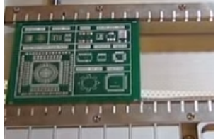
Figure 1 – Clamping System
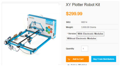
Figure 2 – XY Plotter Robot Kit
References:
Brian Dorey’s SMD Project
http://www.briandorey.com/category/DIY-Pick-and-Place
Manufacturing
Nasser Alsharafi (Manufacturing)
Vacuum System
The vacuum pump works as follows. Essentially the air compressor or vacuum pump is connected to a one-way check valve. The one way check valve is a standard mechanical device that cost around 12$. The one way check valve is connected to an electric solenoid. The solenoid is controlled via a microcontroller programmed for specific timing intervals. The size of the solenoid hose connection should be ¼”.
The solenoid then connects to the pick up needle that is specified below. The needle needs to be small enough to pick up the smallest SMD part that it can. The tank is not needed however can be useful if it is disconnected or inactive for a period of time.
Vacuum Pump
The vacuum system is currently being researched and optimized. One thought is an electric air compressor, and the other is a 1200CC aquarium pump. The one way check valve, solenoid, computer-programmed microcontroller, are already specified but can be changed as necessary later if the project is altered in the future. The nozzle is being researched. So far specification for a 0.41 by 0.19 nozzle have been found and priced at 30$. The aluminum surface can be custom ordered to any size necessary.
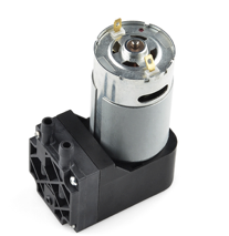
Figure 1 – Sparkfun Vacuum Pump
This is the Sparkfun Vacuum pump 12V. It cost around $15. It can work under 32° -120° F(0° -50°C). Most people who have used this device praised it for its quality. Most of the projects we researched online used this Vacuum pump for their pick and place projects. The only problem with is device that it might be noisy but since its relatively cheap we can try build a box that can reduce the noise. Also one of the methods that users reduced the noise for this pump is by running at lower voltage for example 8.5 volts, which was still able to lift a whole Bluetooth module. The barb connector is ¼” and should connect to another barb of same dimension.
An objective is that we want to keep the cost as low as we can. Perhaps, we would consider the electrical pumps as first, but if we want to make it cheaper possibly we could take the aquarium air pumps as an option. Aquarium Air pumps need to have the ability to make the tube pressured enough to pick the chips and place them at the board. As an example of an Aquarium Air pump we would consider Aqua Culture with 20 to 60 gallons, and its price is 7.61$. It has the ability to pump 1200 CC per minute. On the other hand, we have the electrical pumps that will be around 59$. Many reviews on the Aquarium Air state it has substituted the expensive electrical pumps very well.

Figure 2 – Aquarium Air Pump
Nozzle Head
After that we researched the nozzle head. We found multiple ways that people implemented the nozzle head. Our requirements list that our nozzle must be smaller than the smallest 0402 component, which is 0.4 mm x 0.2 mm. we found many nozzles that can work for our project and the following is an example.

Figure 3 – Vacuum Nozzle
References:
Sparkfun Vacuum Pump:
https://www.sparkfun.com/products/10398
Nozzle Head:
http://www.aliexpress.com/store/product/SMT-MV-0402-NOZZLE/1457082_2050995547.html
Aquarium Air Pump:
http://www.walmart.com/ip/10532634?wmlspartner=wlpa&adid=22222222227001219214&wl0=&wl1=g&wl2=c&wl3=40341924752&wl4=&wl5=pla&wl6=56968315625&veh=sem
Christopher Andelin (Project Manager)
Mario Ramirez (Systems Engineer)
Qui Du (Manufacturing Engineer)
Andrew Laqui (Electronics and Controls Engineer)
Henry Ruff (Electronics and Controls Engineer)
Table of Contents
Christopher Andelin (Project Manager)
Source Material
Mission Objective and Mission Profile
The Project Objective and Mission Profile is a statements of a problem to be solved. If along the way the customer changes their minds it is okay to let the customer know that the change is out of scope and there may be an increase in cost of schedule slip. The Mission Profile confirms that the Engineers design solves the customers’ problem through validation tests.
The Spring 2015 Mission Object biped project does not state a problem to be solved instead explains that the goal is to shrink the design to a micro biped. The Mission Profile comprises of validation tests that are specific and appear feasible due to the design of the micro biped.
Level 1 program/ project requirements
The requirements of Spring 2015 biped project done correctly
Done incorrectly
Costs
Scheduling
The Spring 2015 biped team spent a lot of time on planning, reviewing code, selecting a microcontroller, manufacturing, software and testing. It is advised to prepare for unforeseen circumstances (source 4).
Mario Ramirez (Systems Engineer)
Source Material
1.”Project Biped”, 1/31/2016 http://www.projectbiped.com/prototypes/rofi
2.”Fall 2015 microBiPed Summary”,BiPed, Page 1, 1/31/2016 https://www.arxterra.com/fall-2015-microbiped-summary/
3.” Fall 2015 MicroBiPed Verification and Validation Tests”, BiPed, Page 1, 2/1/2016 https://www.arxterra.com/wp-content/uploads/2015/12/Test-Plans-for-Verification-and-Validation.pdf
4.” Fall 2015 MicroBiPed Center of Mass”, BiPed, Page 1,2/1/2016 https://www.arxterra.com/fall-2015-microbiped-center-of-mass/
5.” Fall 2015 MicroBiPed Stress Analysis”, BiPed, Page1,2/1/2015 https://www.arxterra.com/fall-2015-microbiped-stress-analysis/
6.” Fall 2015 MicroBiPed Wiring Diagram”, BiPed, Page ,2/1/2016 https://www.arxterra.com/fall-2015-microbiped-wiring-diagram/
7.” Fall 2015 MicroBiPed Center of Mass”, BiPed, Page ,2/1/2016 https://www.arxterra.com/fall-2015-microbiped-center-of-mass/
RoFi is a two legged BiPed robot designed by Jonathan Dowdall. RoFi should be able to walk on only two feet without falling over, avoid walls as well as other objects. RoFi should be able to do these operations by communicating with the Arxterra app.
As the system engineer of the RoFi project group I am in charge of assisting with level 2 requirements, the cable tree, box diagrams, intangibles, testing, and verification/validation. Reviewing Jonathan Dowdall’s website and the BiPed section on the Arxterra blog I have come up with a review of RoFi.
Level 1 requirements for RoFi consist of maintaining balance, be able to detect and adapt to incline or declines, avoid walls and objects using an ultrasonic sensor, and be able to communicate with the Arxterra app. Most of requirements posted by previous teams were for a microBiPed. Since we are working with an original size BiPed the level 1 dimension requirements do not apply to us and were omitted. All these requirements are qualitative in my perspective because they give exact detail on what RoFi must be able to do and also lead to a design and further level 2 requirements.
Level 2 requirements for RoFi specify what is going to be designed in order to achieve the level 1 requirements. For the level 1 requirement of avoiding walls to be met the level 2 requirement should state what sensor is being used and the reasoning behind it. Some previous groups state using a ultrasonic range sensor and other groups do not state the sensor at all in their requirements. For our level 2 requirements to lead to a proper design I think we need to state what sensor we will be using and why we chose that sensor. Another level 2 requirement obtained from the blogs will be the use of a gyroscope to sense the incline or decline of the surface. However, some research has lead me to believe that the gyroscope is not the most effective sensor. Testing an accelerometer and comparing it to a gyroscope might lead to possible solutions. Other level 2 requirements consist of: usage of Arduino Mega, Bluetooth used to communicate with Arxterra app, and grip pad on the soles of RoFI. These requirements meet a qualitative and quantitative criteria in order to push the design of the project forward.
Validation/verification go hand in hand with requirements because the validation form goes through the requirements and states if and how those requirements were met. I think previous teams did a good job with their validation form because I was clearly able to understand what requirements were easy to meet, which were more difficult, and which requirements were not able to be met.
Tests done for the BiPed robots consist of power distribution testing, servo torque testing, limb strain testing, and center of mass testing. The blogs from previous teams state clearly the experiment they did and the results achieved. However, not much detail in the process of how the experiment was always given. I think enough detail should be given so the next engineer could redo the experiment if needed. I also believe more testing on the ultrasonic sensor should be done. Previous teams have testing on the connections of the sensor, but I did not see testing on the range of the sensor or if any objects cannot be distinguished by the sensor.
Intangibles are an important task for the systems, missions and tests division of any project. I read some intangibles within tests of previous teams, but for clarity and future teams I believe a structured table would be beneficial so it is clear what teams in the future need to test for their design.
Andrew Laqui (Electronics and Controls Engineer)
Source Material
https://www.arxterra.com/microsegbot-fall-15-final-document/
https://www.arxterra.com/spring-2016-velociraptor-roles-responsibilities/
The level 2 requirement #7 from the MicroSegbot project from Fall 2015 stated that the robot must utilize a microcontroller that will support each component that is used in accomplishing the program requirements.
The Bluetooth Trade-Off Study from the MicroSegbot project from Fall 2015 considered the level 2 design requirement #3. The author stated that Bluetooth communication was required because the robot was to be controlled by an android phone.
The Microcontroller Trade-Off Study from the MicroSegbot project from Fall 2015 considered the level 2 design requirement #7.
The level 2 requirement #1 from the μBiPed project from spring 2015 stated that the robot will utilize an HC-SR04™ ultrasonic sensor. The reason for this sensor is that it is less susceptible to noise and cost.
The level 2 requirement #9 from the μBiPed project from spring 2015 stated that a Bluetooth IC will be chosen to communicate with the Arxterra™ program. An IC must be used in order to minimize the μBiPed size and mass. The type of Bluetooth IC is HC-06.
Qui Du (Manufacturing Engineer)
Objective:
As a Manufacturing Engineer, I will be responsible for the PCB layout and assembly. My job is using the Eagle CAD programing to design the PCB (printed circuit board), perform ERC (electrical rule check) and DRC (design rule check), and generate the CAM file and upload to PCB house for fabrication. Beside of this, I also will be responsible for 3D modeling to design all Rofi printed parts by using Solidworks.
Source Materials:
https://www.youtube.com/watch?v=TvBoZ6kH3Q8
https://www.arxterra.com/fall-2015-microbiped-pcb/
https://www.youtube.com/watch?v=1AXwjZoyNno
REVIEW OF MATERIALS:
This video also shows how to optimize for different target speeds (different dimension of a biped have different target speeds). For example, for a too wide Bipet, we will be faced with an issue of low speed; however, for this type of biped, we will take an advantage of avoiding the biped to fall sideway. In contrast with a too wide Biped, a too tall Biped could achieve a high target speed, but it has an issue with being easy to fall down to all direction. From this information, I realize that the outfit of a biped is very important consideration to design a good Biped which could match with requirement of balancing and achieve a target speed. In other words, in order to design a desirable target speed biped, I really need to design the right outfit for the Biped.
Henry Ruff (Electronics and Controls Engineer)
Source Material
Project Biped
Jonathan Dowdall
Arxterra
Review of Literature
Project Biped – This documentation on projects ROFI and ROTH provides insight on design complications and specifications necessary for the requirements of building a bipedal robot. These studies elaborated on level-2 design requirements, with each portion working towards furthering the overall design. For more detailed specifications, the ROFI parts list provides exact components used previously, and this is a useful reference point. The ROFI website itself is a more direct resource as compared to the Arxterra posts, as the latter is not specifically for ROFI itself.
Arxterra – The Arxterra blog posts presented insight on component options and testing performed by previous, comparable biped projects. Furthermore, they outlined requirements for biped projects that can similarly be applied to the ROFI robot.
Requirements – A compilation of understanding of the previous articles, as well as observations and personal commentary on necessary adjustments or changes to the project overall.
Christopher Andelin (Project Manager)
Mario Ramirez (Systems Engineer)
Qui Du (Manufacturing Engineer)
Andrew Laqui (Electronics and Controls Engineer)
Henry Ruff (Electronics and Controls Engineer)
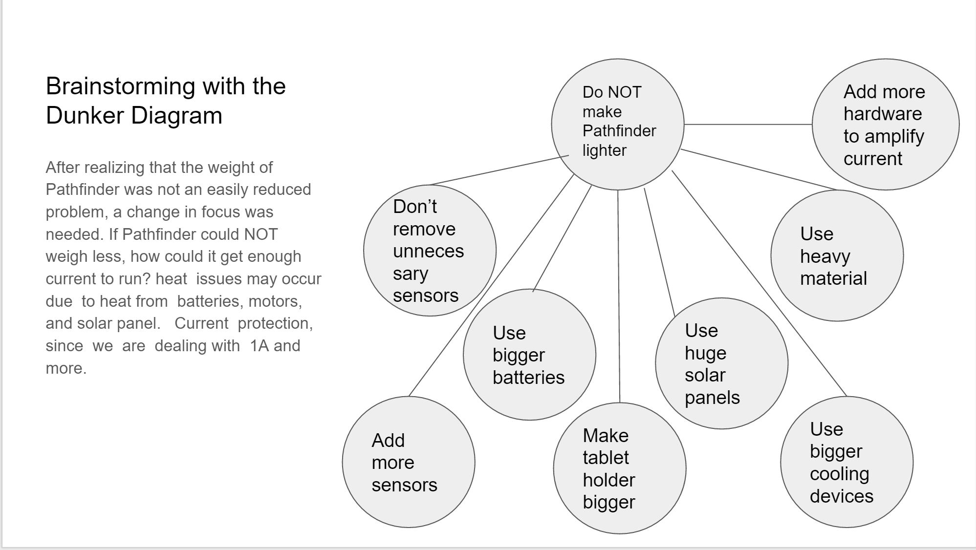
Problems
Brainstorming Solutions
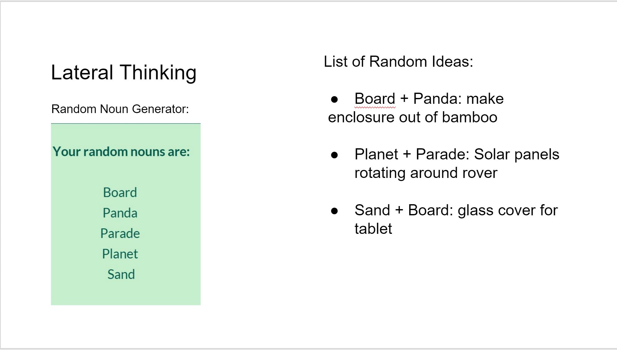
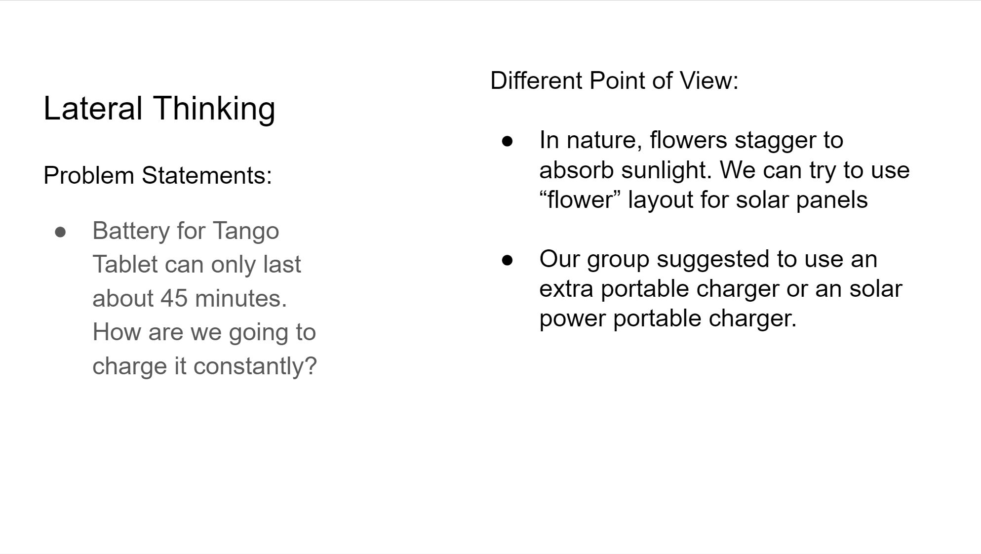
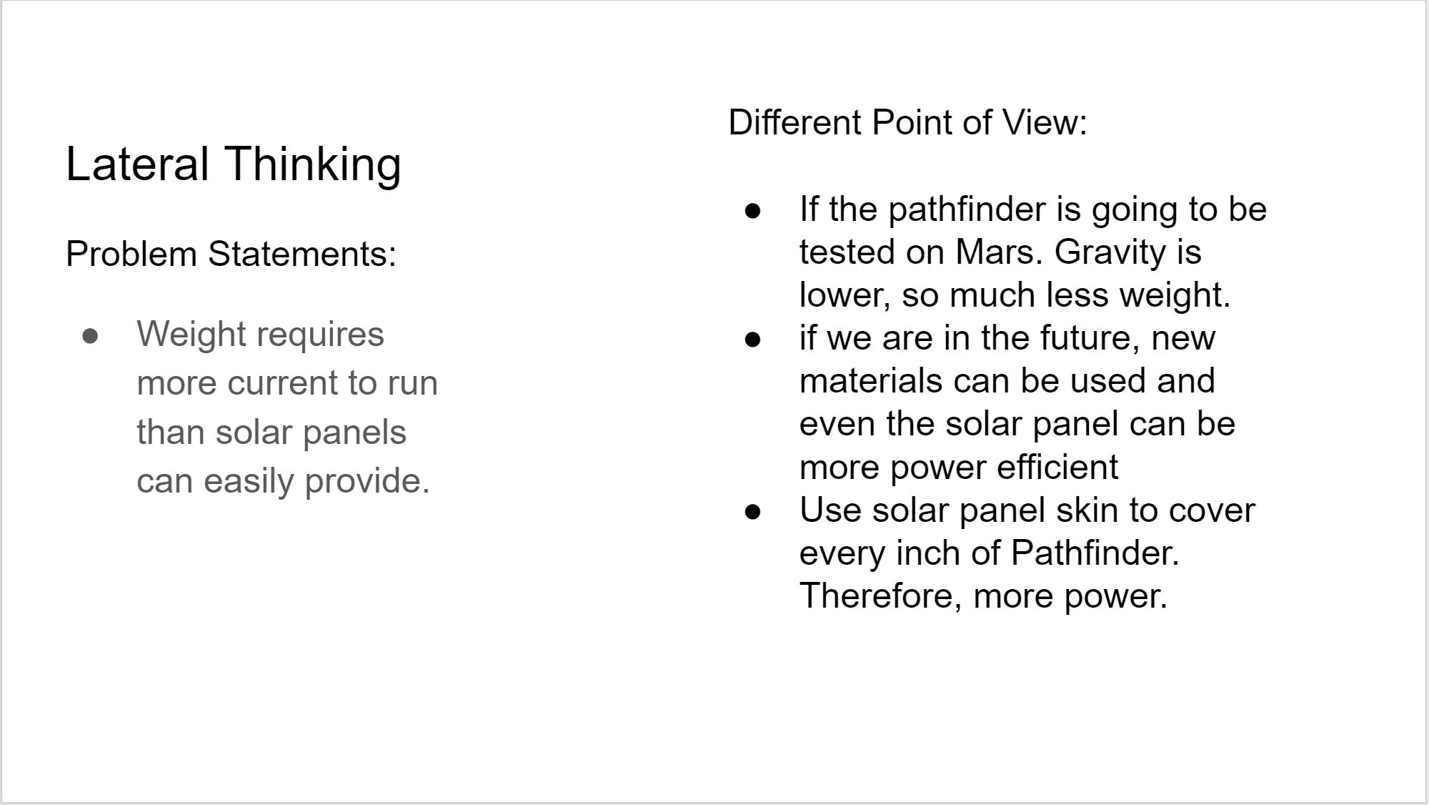
Lateral Thinking
Forced Relationship:
Different Point of View
Experiments
Questions
By Mikhael Semaan (Project Manager), with contribution from Jeremy Seiden (Mission, Systems, and Test), Chelsea Mediavilla (Electronics and Control), and Eric Hanna (Design and Manufacturing).
We review our roles through Club-provided reference material and through previous semesters’ blog posts. From this review, we formulate preliminary Level 1 Requirements, hint at Level 2 Requirements, and provide ideas for the direction of our project towards achieving the Club’s goals.

Ayman Aljohani (Project Manager)
Tae Lee (Mission Systems & Test)
Kevin Moran (Electronics & Controls)
Rickeisha Brown (Manufacturing Division)
Jerry Lui (Manufacturing Division)
By: Ayman Aljohani (Project Manager):
The 3-Dot Goliath is a new project that will be working with a new board referred to as the 3- Dot board.
As a project manager, I will be responsible of my team’s final product, and making sure it meets the customer’s requirements (level 1 requirements) which are:
From researching past projects, we have our preliminary budget as follows:
In order to meet those requirements, I have developed a work breakdown structure (WBS) where the the work is broken down into tasks assigned to each division with a deadline.
A prototype version of the project is schedule to be tested on week 5 of the semester.
A research on sensors in terms of (field of view, cost, safety, and interference from outside source) will be assigned to Systems engineer .Based on the research results, the type of sensor will be determined to be one of the following:
IR – LED – Laser – Ultrasonic
The research will be joined efforts with our opponent robot team (3DOT Spider).
One important decision should be made as soon as possible is the type of communication devise used in laser-tag battle.
Source materials:
By: Tae Lee (Mission Systems & Test) :
Source Material:
Introduction
The 3D Dot Rosco is a new project that will require a little bit of research. We will be working with a new board referred to as the 3D Dot board.
Some of my responsibilities are performing
From researching past projects I have noticed they used the Arduino board, Arduino motor shield, and a Bluetooth module that will be used to program a rover to do various tasks [7]. However, the new 3D dot board now incorporates all the hardware into a single board that will be used to control and perform various tasks on the rover. The 3D dot has dimensions 1.38 x 1.73 inches making it portable and convenient when printing 3D parts for the RoSco. Using the Arduino programming language (C++) we will then code and test the servo, motor, control panel, and the Bluetooth module[7].
Review of Literature:
Trade Off Studies of Batteries Review:
The blog post provided information on the research to determine which types of batteries will be suitable for the rover.
Notes for Requirements:
The research that was conducted on the type of batteries seemed unnecessary. This section should be replaced with a tradeoff study on the uses of different batteries. The group provided with informative information on the characteristics of the battery. However, it is more important to provide calculations to determine which battery will last longer for the rover. This requirement of comparing batteries does not contribute with moving the design forward. It would be better to narrow down a few batteries and documenting the amount of current that can be produced by the battery. Next step will to determine the milliampere-hour by adding up all the currents drained from each device to determine the total current. By doing this we can than calculate an approximate value of how long the rover will last by multiplying the total current with the desired operation time [1].
Level 2 and Level Requirements Review:
The rover team provided a good understanding of the level 2 requirements before building the product. They performed research on the terrain for obstacles and the distance that is needed to travel to fulfill the requirement. This included simple calculations to approximate the distance that was needed to travel. In addition, provided information and calculation of determining the required speed of .05 m/s. The next requirement was to determine a battery that will be used on the rover to last 20 minutes. Performing a simple calculation, they were able to determine the type of battery needed (890mAh) [2].
Note on Level 2 Requirements:
A recommendation to improving the blog is to combine the level 2 and level 3 requirements. An example of this is when they discussed the Power and the Power Storage. These sections are closely related and should be combined to make it clear to the reader of choosing the battery that will be used on the rover [2].
I agree with most of the level 2 requirements; however, the power storage will be modified because of the various components that will be used on the rover. The rover will be using a Bluetooth module, 3D Dot Board, laser, laser sensor, and two motors. This will require different type of battery that will power these components. In addition, the speed requirement will be changed by the customer needs.
Laser Communication Device:
We need to implement a sensor that is able to receive a certain wavelength from a laser. Once the laser hits the sensor it will send a signal to an LED or a buzzer to indicate we got hit by the enemy. The laser and the sensor will be connected to the 3D dot board and controlled by a wireless controller. This field will be further researched to be implemented on our rover [3].
New Requirements:
System Block Diagram:
The systems engineer provided a satisfying block diagram that shows the electrical interface of the rover. This includes the connections for the motor, illuminator, pan & tilt motor, and other components powered by the battery. We will be able to apply a similar block diagram with a few changes to help us create the new rover [4]. These changes include the laser, laser sensor, and the 3D Dot board.
By : Kevin Moran (Electronics & Controls):
Sources material :
Double Gearbox Motor
For more info on batteries
http://batteryuniversity.com/learn/article/understanding_lithium_ion
Level 2 Requirements: (Based on requirement to make a “low budget” and “cool” rover)
In this year’s project we will be using the 3DoT board which comes with a motor shield and a voltage booster from 3.5V to 5V to control the motor speed. I will be testing the board to ensure it meets the requirements to power the rover. The motors should not exceed a combined force of 5V since that is the board’s limitations
In order to meet the level one requirements for a game of laser tag, the length of the game must be decided in order to ensure the batteries chosen for the task of powering the rover last until the end of the game. The selection of the batteries will depend on their mAh, their discharge rate, and size. Since our rover is the next generation and because of level 1 requirements, we must ensure it fits in the overall design of rover.
Level 1 requires that a game of laser tag be played between the Rosco team and the Spider bot. The length of the match is still to be determined. Lasers will not be allowed in this laser tag game. An LED will be used in its place. In order to be able to hit a target, the LED must be focused on the objective.
Rover from previous generations:
In order to build a next generation rover, I read the documentation on previous projects, trying to learn from their successes but also their mistakes. To demonstrate the effectiveness of the 3DoT board, our rover must exceed previous expectations and results. Below are a few of the experiments done by previous groups.
In order to ensure the survival of the rover through its respective test course, the team needed to waterproof their servos to ensure full functionality in wet conditions, and completion of the required task. They enclosed the PCB in waterproof box. They had to spray the servos with plastic dip and submerged them under water for thirty seconds in order to prove they were safe to work in wet conditions. The only problem I see with this way of waterproofing is in the long run of the project. For our specific project we will not be able to waterproof this way, for we are not using servos. However, since we are using a prototype 3DoT board we need to be extra careful to protect from any outside interference, such as a single drop of water. All of our circuitry must be inside the rover and protected by our 3D printed rover.
In order to fully simulate a soldier crawling through a barbed wire course, the designed their rover to avoid obstacles, to match the speed of a soldier, and visualize what a soldier sees in the crawling position. They tried to find the information on the internet but were not successful, so they decided to perform an experiment on field of vision. They needed the field of vision of a HTC Evo phone.
The majority of the power was used by 6 different servos and 4 different motors. They needed to know the current the rover uses in order to figure out if their batteries were enough to complete the task. They were given batteries with 700mAH capacity, 7.2V batteries were used on previous semesters. By building their prototype, they were able to determine the exact current their rover would use when it was operational. They discovered that their batteries allowed them to run their rover for 40 minutes. For our project I need to determine how much power the laser will use, and for how long our game of laser tag will last. I need to ensure sufficient battery life for the motors and the laser circuitry. Since it is our first time using the 3DoT board, I will also need to run experiments and seeing how it functions and if it uses up much battery life to function since it’s such a compact design
New Ideas to meet level 1 requirements
Since the rover has been done by previous teams before using the Arduino plus a motor shield along with other components, in order to make our project a new generation we must improve on previous models. However, we must be realistic, we will not be reinventing the motor or the batteries used for the rover. Our focus will be to improve on previously known data. We will choose a similar motor and batteries but according to our 3DoT board, to ensure full cooperation amongst the subsystems. Below are some ideas to meet the level 1 requirements
By: Rickeisha Brown (Manufacturing Division):
Source Material :
Manufacturing our rover incorporates the actual publishing and printing of the PCB board, soldering IC components and other necessary components to the IC board, along with designing 3D structure components. We will use Eagle Cad to draft our design of circuit boards, create a Gerber file and place an order with a PCB manufacturing company of the Manufacturing Division Manager’s choice. It is vital that we confirm with systems and controls a final PCB board design before moving forward with Eagle Cad and Gerber files prior to printing. It is our goal to utilize production time effectively for adequate testing time.
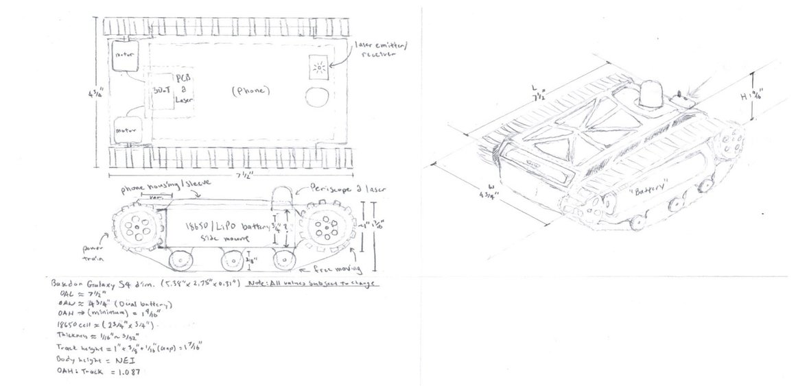
As stated, we are responsible for the 3D design of rover components on a computer software that allows us to do so. For the sake of time ease and access, our manufacturing team will use SolidWorks. SolidWorks will allow us to draft all parts required to manufacture our rover including: the chassis, gears, battery holder and shell.
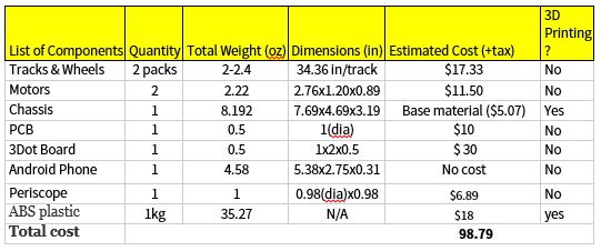
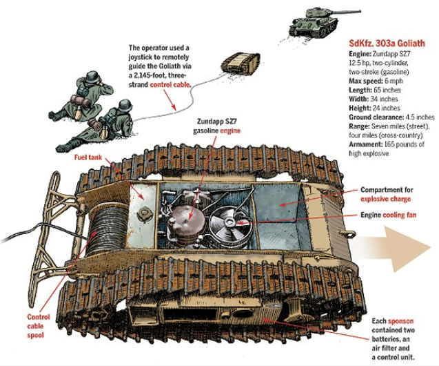
The customer requests that our manufacturing team design a rover which mimics the German Rover Goliath. The German Rover Goliath has a distinct height and length ratio, such as 1:3. However, the most recent rover designs are replicas of Mars Rover and/or NASA’s Curiosity Rover, which have a height/length ratio of 3:1. Goliaths requirements:
Estimated total weight of Goliath Rover: 1.88-2.00 lbs
The manufacturing division will be responsible for the generation of an Eagle Cad design of the PCB Board, a 3D model of our Rover design using SolidWorks, & the calculation of material and supply needed to build the desired design.
By: Jerry Lui (Manufacturing Division):
Sources materials:
http://www.toybuilderlabs.com/blogs/news/13053117-filament-volume-and-length
http://www.amazon.com/gp/product/B001VZJDY2?refRID=BT3DN2GHRMF7CEJ988CY&ref_=pd_ybh_a_4
Level 2 subsystem requirement
Chassis material has to be light weight (at least under 1.63lbs)
The overall cost has to be low (<$80)
A game has to be implemented in conjunction with the 3Dot Spider-bot team
The Rover must be similar to the german Goliath ROV
Suggestions