

Requirements
Requirements:
Level 1
- The μBiPed must be finished by the 8th of May, 2015 to correspond with the duration of the EE 400D class.
- The μBiPed must move (i.e. walk in a human-like fashion) up an incline that starts initially at 8° and then decreases to a 6° slope in relation to level ground. This is due to the obstacle course prescribed in the specifications.
- Verification: To test this parameter, the μBiPed will be sent up an incline at varying grades, starting at 6° and going till at least 8°. The incline grade may increase past the 8° in order to test failure point.
- The μBiPed must avoid walls at a distance of TBD. Determined by the mission profile. The distance may be determined based off of the constraints of the parts used to determine distance, or the customer may indicate distance.
- Verification: Will have the μBiPed walk towards an object, i.e. a wall, and see if the μBiPed will stop or try and change path. The distance will be measured with a tape measure.
- The μBiPed must walk over or on an object at about a 45° angle and a height of 2 cm. This is part of the mission profile dictated by the specifications.
- Verification: The μBiPed will walk over an object of about 2 cm +/- 1 cm. The 2 cm is for margin of error. This will be measured by a ruler.
- The μBiPed must walk on surfaces of varying friction coefficients:
- Carpet: 1.0 static
- Linoleum: 0.5 static
- Verification: The μBiPed will walk on all the different types of surfaces. Carpeting will vary, it will range from thick to thin. Verification for each surface friction coefficient was found on the below websites.
- The μBiPed must stabilize when disturbed by a force/time. The force has not yet been calculate. This requirement is dictated by the specifications and mission profile.
- Verification: The μBiPed will be hit to test response to immediate impact, and will be tested for force applied over time, i.e. a push. Force will be measured by a force gauge or equivalent.
- The μBiPed must weigh no more than 1 kilogram in order to facilitate the miniaturized size of the μBiPed. Otherwise, if the μBiPed is too heavy the project may not be realizable.
- Verification: The servos will be tested for maximum torque, then μBiPed will be weighed with a scale and will be checked if it can move.
- The μBiPed must interface with Arxterra Remote Control™ mode as defined by the specifications. The RC mode must be used because the μBiPed must conserve its mass; any additional mass, such as a phone would require the increase of size.
- Verification: The Arxterra Remote Control™ mode will be used to direct movement in the μBiPed. Movement via Bluetooth will verify that connection with Arxterra has been meant.
- The μBiPed must be miniaturized as is dictated by its own name, size 7 inches.
- Verification: The μBiPed will have its size miniaturized compared to its larger model. Measurement will be done with a ruler or equivalent.
Level 2
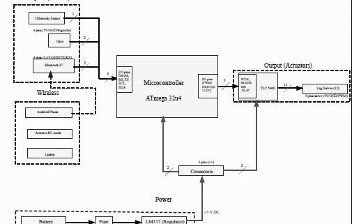
- In order to avoid an obstacle the μBiPed will use an HC-SR04™ ultrasonic sensor. Primary reasons are that it is less susceptible to noise and cost; in addition, the project has one in inventory. Refer to requirement 3, level 1.
- Verification: Based on previous semesters, distance will be determined when height of the μBiPed has been decided to finalize the angle of detection. Calculations will be done similar to previous semesters. Link provided below.
- https://www.arxterra.com/ultrasonic-sensor-examination/
- The μBiPed will use a gyro, type MPU-6050, in order to allow for completion of requirement 2, level 1, and requirement 6, level 1.
- Verification: The μBiPed will be tested on how well the gyro keeps it stable. This will be done by walking over uneven surfaces and not falling over.
- In order to successfully miniaturize the μBiPed, micro-servos will be used. Type of micro-servos are MG92b after testing. The project must test the micro servos using SolidWorks or through math analysis in order to determine if micro servos provide enough torque to complete the project.
- Verification: Micro-servos will be tested on strength and maximum load they can handle based off the load bearing tests.
- In order to miniaturize the μBiPed, a microcontroller, type Arduino Micro, must be chosen. The microcontroller should at least have 14 kb of Flash memory and 4.7 kb of SRAM.
- Verification: Microcontroller will be tested if it can control at least 12 servos and facilitate the additional components needed to implement the μBiPed.
- Reduced the footprint of the code.
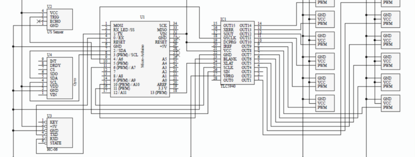
- Due to the miniaturization of the μBiPed, a PCB board will be fabricated that includes the wiring for the gyro, the Bluetooth IC, and the servo pins that will allow for the microcontroller to interface with the assembly.
- Verification: A continuity test to verify proper wiring layout of the PCB.
- In order to traverse multiple surfaces (requirement 5, level 1) the μBiPed’s legs must have some type of tread or rubber sole added to it. Reference.
- Verification: Will test the μBiPed with various types of tread to see the traction difference.
- In order to keep within the specified size restriction, the μBiPed will have light weight batteries. Type of batteries are LIPO 2S 350mAh.
- Verification: Testing and calculations will be performed before selection.
- A light weight material must be used for the frame in order to keep within the specific mass restrictions of the μBiPed; the type of material is PLA. Testing must be done as to whether or not the μBiPed can be made of plastic, or if a lighter material must be used.
- Verification: Different materials will be strength tested and weighed. Strength testing will be verified by hand, and weight will be verified with a scale.
- As mentioned in item 5, a Bluetooth IC will be chosen that will communicate to the Arxterra™ program. An IC must be used in order to minimize the μBiPed size and mass. The type of Bluetooth IC is HC-06. Requirement 9, level 1.
- Verification: To test if the Bluetooth IC works properly commands will be given from the Arxterra Remote Control™ program and the robot will respond accordingly.
Reduction of Dynamic Memory Usage
By: Tate McGeary
As stated in a previous blog, one of the immediate issues that was evident was the lack of resources on the smaller micro-controllers. The micro-controller that was chosen the Arduino Micro has the following resources:
32 kb of flash (4kb for the bootloader): 28 kb flash available for programming
2.5 kb of SRAM (dynamic memory)
While the program will require around:
14 kb of flash
4.7 kb of SRAM
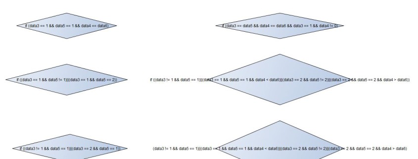
That means the program uses a little under 200% of the dynamic memory. The first task was to go through the code and reduce the variable footprint. All variables that were constant where pushed into flash memory with the PROGMEM, but this did not reduce the SRAM usage enough. It was determined that a majority of the SRAM was used due to the tables that stored the movement of the BiPed. These tables could not be stored in flash in the original code due to the modification the tables went through. In the original code the tables had to be modified through the use of a calibration sub function because the frames are usually different BiPed to BiPed.
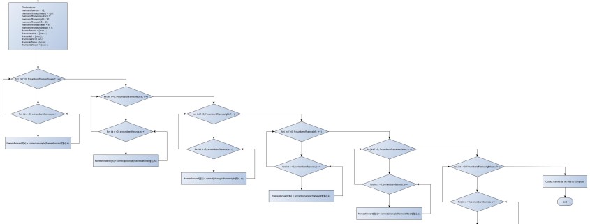
Using Robot Poser from Dr. Dowdall, a servo calibration table is created and inserted into the original code. From there the sub-function called calibration(), will then map the servo calibration table to the proper frames used for the BiPed locomotion phase. The calibration() function is what uses a majority of the SRAM simply because it is actively modifying the tables stored on the Arduino which are rather large.
To overcome this two methods were thought of. One is to separate the calibration() code and have an Arduino MEGA output the data to a text file on a computer. Another method is to use Processing 2.21 (a JAVA type language) or MATLAB. By looking at a flowchart of the calibration code ( see below) one can see how it can be applied or modified to fit a different platform other then the original code.
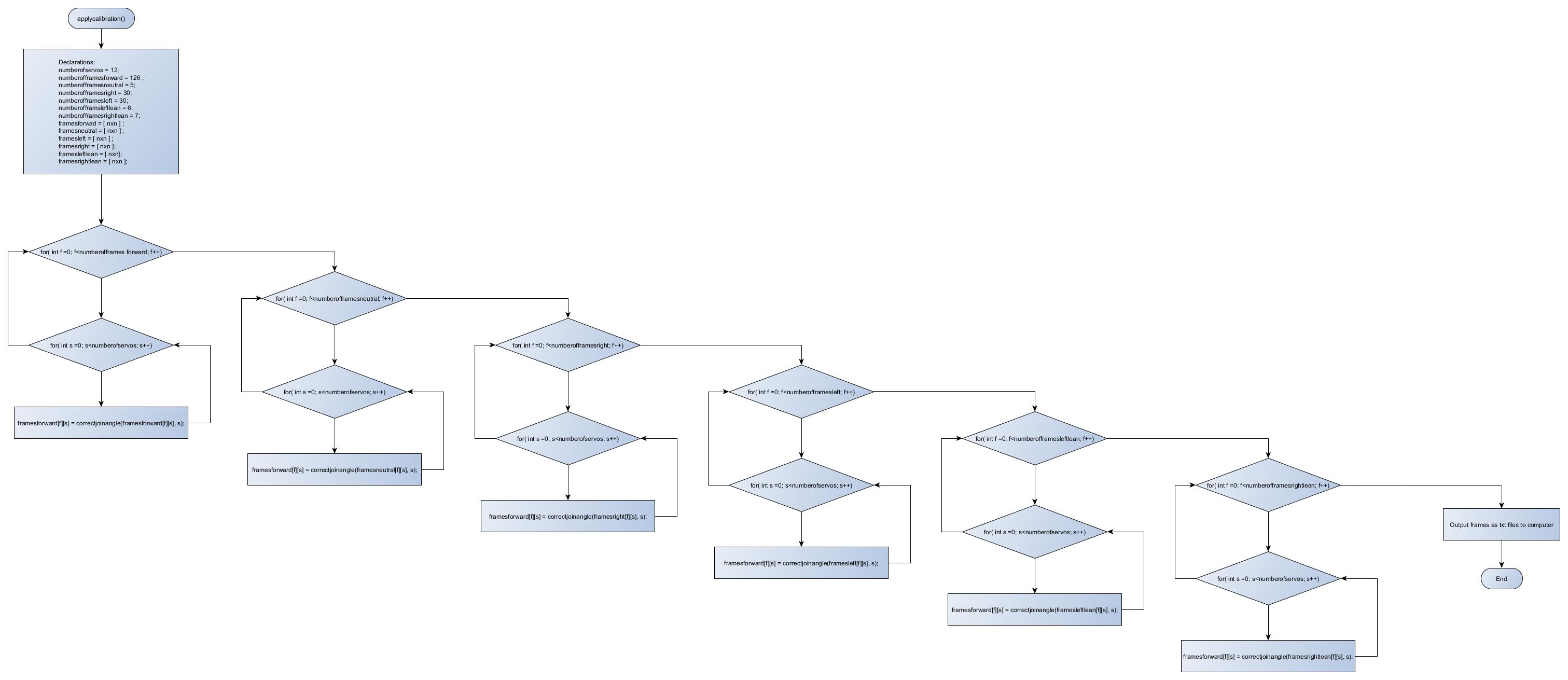
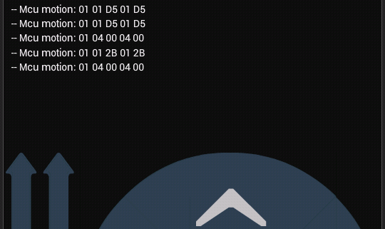
Right now, the group is working on the calibration() code for the Arduino MEGA outputting data to a computer and a MATLAB code. However, a version for Processing 2.21 is being tested and completed using Dr. Dowdall’s logic, variable declarations, and method. The project chose Processing 2.21 in case an individual wanted to reduce the footprint of the code, but didn’t have access to an Arduino MEGA or MATLAB. As Processing is a free compiler and anyone can access it, the group decided to try and get Processing to do the calibration. Here is a link to the current Processing code.