Level 2 Requirements – Final Iteration

By Kristine Abatay – Project Manager
& Elaine Doan – Robot Company Systems Engineer

The following three requirements are the initial level 2 requirements that were introduced during the Spiderbot PDR:

1. In order to match the speed of the rover project while on a flat surface, the servo motors will need to move a distance covered by 60 degrees in 0.13 seconds and utilize a tripod gait – the walking style that will allow Spiderbot to move quickest, which will be implemented in the coding of Spiderbot.

This value was obtained using the following calculations done by our controls systems member, Matthew Clegg.

To try to estimate a possible speed for Spiderbot, he first calculated a velocity based on the speed of the servo motors. A servo’s rated speed is how fast, in seconds, the arm can move 60 degrees. To apply this to Spiderbot, he took into account the motion of the bot in a tripod gait. The gait is the specific sequence of leg movements executed when Spiderbot is in motion. An analysis of the different possible walking styles that Spiderbot is capable of can be found in the following blog post link from last semester’s Hexapod project: https://www.arxterra.com/hexapod-gait-description/. The study will show that the most efficient possible walking style that Spiderbot can use is the tripod gait.

These calculations can be found at the following link to a previous post, which lays out the calculations used to determine these values:

https://www.arxterra.com/speed-calculations-component-modification/

Test: Since this time value is so quick, measurement of this speed will require implementation of a video recording device and slow motion playback in a video editor. Code will be run through a breakout board and Arduino to a servo that will be placed on top of a protractor, which will be marked off to accurately measure 60 degrees. A digital stopwatch will be placed near the servo and will increment its time while the servo motor operates. A video of the motor will be captured and opened within a video editing program which will modify the video to play in slow motion. This way, the milliseconds portion of the watch will be easier to read and the time for the servo motion can be recorded.

2. In order to meet the safety requirement outlined by the level 1 requirements, Spiderbot will need to be constructed from materials that will prevent it from being labeled as a hazard. Avoidance of materials such as LiPO batteries in the Spiderbot design will help achieve this.

Test: According to the Injury and Illness Prevention Program for CSULB (found here: http://daf.csulb.edu/offices/ppfm/ehs/programs/iipp/#policy1), “All…hazard class scenarios shall also be immediately reported to SRMIS and each will be addressed on a case by case basis with the individual college or department manager”. If the final construction of Spiderbot does not garner the attention of SRMIS by falling under the category of one of its four hazard classifications, then Spiderbot will have met the safety requirement.

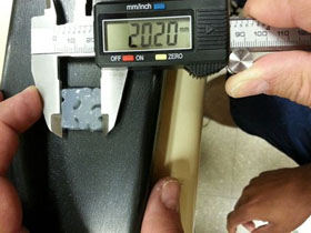
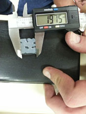
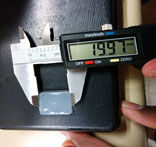
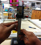
3. To meet the clearance specifications of 4 inches in height and 2.5 inches in width, Spiderbot’s 3D design will need to be at least 5 inches in height and 3 inches in width. The following design considerations were developed by Simon Abatay from manufacturing, to determine these value choices.

The femur length is chosen based off of reasonable servo specifications. Standard servo speeds from 0 to 60 degrees vary from 0.08 to 0.2 seconds. The femur length and servo speeds are critical for the spider to reach the speed requirement of 0.2003m/s.  Based off of calculations, if the femur length is chosen to be 5 inches, the servo must rotate from 0 to 60 degrees along its z-axis within 0.12 seconds. If the femur length is chosen to be 3.5 inches, the servo must rotate at a speed of 0.09 seconds. This relationship shows that the longer the femur, the greater the distance traveled, thus the slower the servo has to move. Realistically, it would be ideal to choose a femur length that is longer than 3.5 inches. This is because finding a servo that moves at a speed of at least 1.2 seconds under load is more realistic than finding a servo that moves at 0.09 seconds under the same load.

Test: These clearances will be checked within the SolidWorks. Once a complete leg and chassis design are made, the pieces can be connected in the program, and if the measurements done allow for the obstacle clearances, then this requirement will have been met.

This next list of additional level 2 requirements was written with minimal guidance from Robot Company’s Systems Engineer, Elaine Doan, who wrote the requirements for this semester’s Hexapod project, alongside Hexapod’s Computer Systems and Software member, Chau To:

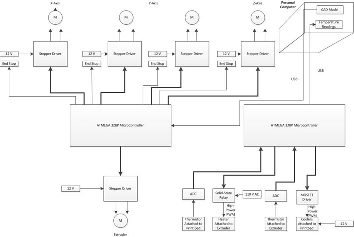
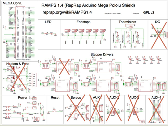
4. In order for Spiderbot to receive commands from the Arxterra Android App, via the Arxterra Control Panel, the microcontroller used must have a USB host interface.

For this reason, an Arduino Uno – R3 will be used, which will allow for communication, but will not accommodate all of the servos that will be used for Spiderbot.

Test: Send a command to the Android smart phone being used by Spiderbot, using the Arxterra control panel, and if the command executed matches the command that was sent, then this requirement will have been verified.

5. The microcontroller used must also provide connections to accommodate pins to control 20 servo motors.

Since the Arduino Uno – R3 does not directly accommodate all 20 servo motors, two Adafruit 16-ch 12-bit servo drivers will be used to provide power to them.

Test: Connect the servo driver used, along with a servo motor, to the microcontroller chosen and run a basic Arduino command. If the command sent to the servo motor matches the action executed by the servo motor, then this requirement will have been verified.

6. In order for motion of Spiderbot to occur, its battery will need to supply at least 10800 mAH.

This value is an estimate that accounts for the 18 servos that will be used to control the legs of Spiderbot, which is where a majority of the current will be allocated. The value was obtained from testing of the Power HD servo motors, whose results can be found here:

https://www.arxterra.com/current-test-of-the-power-hd-high-torque-servo-1501-mg/

The maximum current that was drawn from the servo motors, using a supply of 6V, was 0.6A. Multiplying this value by 18 yields the 10800 mAh stated above. Of course, this value overshoots the true amount of current that will be used by Spiderbot, considering the fact that all of the servo motors will not be drawing their maximum current simultaneously.

Test: Connect Spiderbot to power and let it run. If it lasts for at least 1 hour, then this requirement will have been verified.

Spring 2014 Biped Final Thoughts

By Kevin Huynh, Project Manager

Tasks Complete:
Alternative movement code to the one provided by projectbiped and robot poser. Alternate code includes statically stable forward walk, left turn, right turn, and obstacle avoidance code.

Remote control of ROFIA through Arxterra. ROFIA can be commanded to stand up straight, walk forward, turn left, and turn right.

Servo overcurrent protection using polyfuses.

Ideas for future classes:
Develop the ability to walk backward or to walk sideways. Add these abilities to the Arxterra control panel along with options to move the head servos.

Consider using lower torque servos for joints that do not need to rotate as much weight to minimize current consumption. For example, look at how ROFI has the higher torque servos (Power HD 1501) to control the hip, upper leg and middle legs and lower torque servos (Towerpro MG99R) to control the
knee, lower legs, and ankles.

Look into implementing an IMU board into ROFIA for active control and the ability to react to external forces.

Minimize the mass unbalance caused by the USB cable from the phone to the Arduino.

Find a way to monitor the voltage of the LiPo batteries for safety purposes.

Molding Parts

By Vinh Kim, 3D Modeling and Manufacturing

Introduction:

Here I will show you the process of molding and casting the Hexapod parts with pictures.

Tool & Supplies:

  1. Sliding Compound Miter Saw
  2. Hardwood Flooring
  3. Mold Max 40 or OOMOO 30
  4. 3D- printed parts
  5. Glue gun & hot glue
  6. Ease Release 200
  7. Vinyl gloves only (Latex gloves will inhibit the cure of the rubber)
  8. Drill
  9. Screws
  10. Digital Scale
  11. Measuring Tape
  12. Disposable plastic cups
  13. Safety Glasses
  14. Utility knife
  15. Clamp
  16. Disposable Wooden Chopstick

Making the Mold Box

figure 1

Figure 1: Thank you to Ali the manufacturing manager for printing the Hexapod parts. Here I have the Hexapod 3D printed parts ready.

figure 2

Figure 2: Here I measured (minimum of ½” of space on all sides of model see Figure 5) and cut the hardwood flooring using a sliding compound miter saw.

figure 3

Figure 3: Using the two free 12 in. Ratchet Bar Clamp I got from Harbor Freight by using a coupon to clamp the wood that I cut together, so I can drill the holes and put the screws in. Here I am using a M3-0.50 x 12 mm screws, than I used a drill bit size 2.50 mm to punch the holes.

figure 4

Figure 4: Next I used a 1.60 mm drill bit to drill the holes in the 3D printed parts and screwing the model down with a M2-0.45 x 12mm screw to prevent the 3D parts from moving. Also to prevent rubber from leaking out of the mold box, I used hot glue to stick it around the interior edges.

figure 5 a     figure 5b

Figure 5a: Mold box done.                                      Figure 5b

Pouring Mold Rubber

figure 6

Figure 6: Once again, thanks to Ramon Luquin (Fall 2013 Hexapod Project Manager) for donating some mold and casting material to the Hexapod team.

figure 7 

Figure 7: Here I’m using rice to estimate amount of rubber or you can go online at http://www.smooth-on.com/tools.php to use a Material Calculators “How much liquid rubber do I need?”

figure 8

Figure 8: Using Mold Max 40.  It will be mixed in a 10:1 ratio. I am using 8 oz for Part A, 0.8 oz for Part B than mixing it together. Vacuuming is required to remove all the air bubbles. When mixing, just make sure to keep mixture stick on the bottom of the container and scrape the sides of the container. Than keep on swirling in circle until you get a solid green color.

As for OOMOO 30, I need mix a 1:1 ratio than I would use 4.4 oz for Part A and 4.4 oz for Part.  However for this particular kind, it’s not required to vacuum this product since it has a low mixed viscosity.

figure 9

Figure 9: Spray a light-mist coating inside the molding box, so when you remove the rubber it does not stick to the model.

figure 10 

Figure 10: To prevent air bubbles. Pour the rubber into a corner of the mold box and allow the rubber to flow evenly throughout the model. Let it cure and rest for 24 hours.  OOMOO 30 only required 6 hours to form.

figure 11 

Figure 11: Finally, after rubber has cured, remove the retaining walls away from the cured mold.

figure 12 

Figure 12: Molding done.

“HEXAPOD – the Movie” Trailer

By Mason Nguyen – Project Manager          

A short trailer that was filmed by our team during this semester!!!

https://www.youtube.com/watch?v=3NniqIkw-64&feature=youtu.be

Improvements to the Bioprinter

By Ali Etezadkhah – Project Manager

While were able to print structures that were well within our stated tolerances, the process is cumbersome at the moment.  There are several features that are missing from the current design, most of which can be easily added to the printer.

  1. The aluminum printing plate is too thin and lacks rigidity.  We were unable to tightly fasten it to the cooler because of its thinness.  As an added bonus, a thicker plate has more heat capacity and will serve to limit temperature fluctuations.
  2. There is no mechanism to level the plate at this time.  A level plate is an absolute necessity for any type of 3D printing.  This can be easily done by fastening the new plate in 3 places.  It only takes 3 points to define a plane and it is far easier to level a plate with 3 screws and springs.
  3. There is no mechanism to easily adjust the height of the nozzles.  Next to the levelness of the plate, the distance between the nozzle and printing plate is also very important.  If the nozzle is too far, the gel won’t stick to the plate and if it’s too close, the flow of gel is blocked.  Ideally the distance should be 0.1 mm, about the thickness of a sheet of paper.
  4. The extruder housing needs to be redesigned with a larger whole on the bottom.  Since we added heating resistors to the dispensing needle, the syringe can no longer be taken out without removing the dispensing needle.  With a larger whole, it will be far easier to fill the syringe.

We would like to thank the Electrical Engineering Department, Biomedical Department, Mr. Gary Hill, Mr. Larry Harmon, Dr. Maryam Moussavi, Dr. Christopher Druzgalski, Mr. Darshit Makawana, and last semester’s biomedical project team for helping us take this project to the next level.

Tolerance of 3-D BioPrinter

By Omair Tariq, Systems and Test Engineer

Purpose

The purpose of this blog post is to determine the tolerance of our 3-D Bioprinter. Our level 1 requirement was that the printed object’s measurement should be within 0.7 mm of the value specified in the 3-D model of the object.

Equipment Needed


Equipment

Quantity

3-D BioPrinter

1

Vernier Caliper

1

2% agarose, 4% starch solution

50 ml

Laptop with Slic3r and Pronterface Installed

1

USB Cables

2

Table 1. Equipment needed for accuracy testing


Perimeter

Value

Nozzle diameter (20 gauge needle inner diameter)[1]

0.6mm

Filament Diameter

29mm

Travel Speed

20 mm/s

First Layer Speed

10 mm/s

Fill Density

1

Fill Pattern

Rectilinear

Top/Bottom fill pattern

Rectilinear

Perimeter Speed

20 mm/s

Small perimeters

20 mm/s

External Perimeters

20 mm/s

Infill

20 mm/s

Solid Infill

20 mm/s

Top solid infill

20 mm/s

Support Material

20 mm/s

Bridges

20 mm/s

Gap Fill

20 mm/s

All Acceleration Controls

0 mm/s2

Table 2. Slic3r Settings used for test print

Procedure

1.)    A 20mm x 20mm x 5mm block was printed using the BioPrinter.

Untitled-1

Figure 1. A 20mm x 20mm x 5 mm cube

2.)    It’s dimensions were then measured using a Vernier Caliper.

l = 19.85 mm (0.15mm within value specified in 3-D Model)

w = 19.97 mm (0.03 mm within value specified in 3-D Model)

h = 5.12 mm (0.12 mm within value specified in 3-D Model)

2

Figure 2. Length of 3-D Printed Cube

3 

Figure 3. Width of 3-D Printed Cube

4

Figure 4. Height of 3-D Printed Cube

Conclusion

The printed part’s length, width, and height were well within the expected range. Based on a single measurements from a single part printed in this procedure, the x-axis has a tolerance of 0.15 mm , the y-axis has a tolerance of 0.03 mm and z-axis has a tolerance of 0.12 mm. This leads us to the conclusion that the printer has clearly met the level requirement of the values being within 0.7 mm of the specified values. In an ideal world, the tolerance would be specified after taking measurements from hundreds of printed parts and the tolerance values averaged. 

Watch a video of the BioPrinter:
https://www.youtube.com/watch?v=0oLHkA7AWBw

Fine Tuning the Printer

By Omair Tariq, Systems and Test Engineer

Scope

There are two issues to ensure correct flow of the mixture: Volume and Temperature Control of extrusion apparatus. The extrusion apparatus consists of a syringe and a needle attached to the base of the syringe. Temperature control was addressed by attaching a heater to the body of the syringe. However, the gel was still solidifying at the base of the syringe and at the needle.  This issue was addressed by attaching high-wattage resistors to the base and the needle. The details concerning the correct temperature control are addressed in a separate blog post. The purpose of this test is to determine the ideal needle diameter and Slic3r settings for the 3-D BioPrinter once the problem of temperature control has been addressed.

Equipment Needed

Equipment

Quantity

3-D BioPrinter

1

Vernier Caliper

1

Agarose Solutions of varying percentages

50 ml

Needles with different gauge diameter

1

Laptop with Slic3r and Pronterface Installed

1

USB Cables

2

Table 1. Equipment needed for accuracy testing

Procedure

For the following test prints, a solid 20mm x 20mm x 5 mm cube was printed

  1. It was decided to start with a 1% agarose solution and a 18 gauge syringe needle[1]. This led to an overflow of the liquid from the syringe as illustrated in Figure 1. Due to this overflow, the liquid did not have enough time to solidify. Therefore, the print was stopped even before the first layer was completely printed. The Slic3r settings shown in Table 2 were used for this test print.  

Untitled-1 

Figure 1 Overflowing liquid


Perimeter

Value

Nozzle diameter (18 gauge needle inner diameter)

0.8mm

Filament Diameter

40 mm

Travel Speed

50 mm/s

First Layer Speed

20 mm/s

Fill Density

1

Fill Pattern

Concentric

Top/Bottom fill pattern

Concentric

Table 2. Slic3r settings used for 1st test print

  1. It was then decided to switch to a needle with a smaller inner diameter: a 20 gauge needle was chosen.  Subsequently, the nozzle diameter and the filament diameter had to be changed in Slic3r. The new Slic3r settings are shown in Table 3. This yielded a much better result as can be seen in Figure 2. The flow was slow enough to facilitate the gelling of the liquid. Even after gelling, the gel structure was not as strong as expected in that it was not able to hold its weight which was a level 1 requirement. Therefore, It was decided to use 2% agarose gel which would be stronger than 1 % agarose gel after gelling. 2% agarose gel has the same gelling temperature as 1 % agarose gel. Therefore, there was no need to adjust the temperature of the syringe.  It was also decided to use 4% starch in the solution to increase the viscosity of the fluid. This slowed down the flow of the liquid through the needle without the need to change temperature. Starch and Agarose are both carbohydrates, therefore adding starch did not alter the viability or biological nature of the solution.

Perimeter

Value

Nozzle diameter (20 gauge needle inner diameter)

0.6 mm

Filament Diameter

29 mm

Travel Speed

50 mm/s

First Layer Speed

20 mm/s

Fill Density

1

Fill Pattern

Concentric

Top/Bottom fill pattern

Concentric

Table 3. Slic3r settings used for 2nd test print (Changes highlighted)

2

Figure 2. Overflowing gel

  1. A test print was then carried out using a 2 % agarose, 4 % starch solution (See Table 4 for exact composition of solution).

The resulting solution had just the right amount of viscosity, which justified the use of starch. The final structure was also strong enough to hold its own weight, which justified increasing the concentration of agarose gel. This structure also had the correct dimensions. But there was one problem; instead of being a solid cube like ‘American Cheese’, the block turned out like ‘Swiss Cheese’ with air bubbles in the middle.

Chemical

Quantity

Water

50 ml

Agarose

1 g

Starch

2 g

Table 4. Chemical Composition of 2% Agarose 4 % Starch Solution

 3a 3b

Figure 3. Test Print using 2% agarose and 4% Starch

  1. During the third test print, it was observed that the travel speed of the extruder increased after printing the first layer. This was problematic since it was not possible to adjust the flow of the liquid for two different travel speeds. Even though the first layer turned out fine, the extruding liquid broke off contact with the structure at certain points in the 2nd layer due to a faster speed. This break in contact in the second layer meant that there was also break in contact in the third and subsequent layers leading to a domino effect. .  We then switched to advance mode in slic3r that gave us a better control of the various speeds of the printer. All these were set to a smaller and equal value of 20 mm/ s. The settings are shown in Table 5. The structure printed using these settings are shown in Figure 4.

Perimeter

Value

Nozzle diameter (20 gauge needle inner diameter)

0.6mm

Filament Diameter

29mm

Travel Speed

20 mm/s

First Layer Speed

20 mm/s

Fill Density

1

Fill Pattern

Concentric

Top/Bottom fill pattern

Concentric

Perimeter Speed

20 mm/s

Small perimeters

20 mm/s

External Perimeters

20 mm/s

Infill

20 mm/s

Solid Infill

20 mm/s

Top solid infill

20 mm/s

Support Material

20 mm/s

Bridges

20 mm/s

Gap Fill

20 mm/s

All Acceleration Controls

0 mm/s2

Table 5. Slic3r settings used for 4th test print  (Changes from previous step highlighted)

4

Figure 4 Final Printed Structure

The actual dimensions of this structure were also very close to the expected dimensions.

5a 5b 5c 

Figure 5. Measurements of Final Printed Structure

Conclusion

A 2% Agarose and 4% starch solution is the ideal solution to be used in the bioprinter. The settings used in Step 4 of this test plan are the ideal settings for the bioprinter when it is being used to print 2% Agarose and 4% Starch solution.

[1] – For needle diameters, check: http://en.wikipedia.org/wiki/Needle_gauge_comparison_chart

A System Overview of 3-D BioPrinter

By Omair Tariq,  Systems and Test Engineer

Untitled-1 

Fig. 1 System Block Diagram of the 3-D BioPrinter

Following is a system engineering perspective of the 3-D BioPrinter

1.)    A 3-D Model is sent as instructions known as G-Code from the Computer to the Primary Arduino (Arduino MEGA) that are then translated by the Arduino, using the RAMPS 1.4 shield’s stepper motor drivers, into movements of the Axes Stepper motors and Extruder Linear Actuator. The instructions are sent via a USB Cable.

2.)    A secondary Arduino (Arduino UNO)  is used to for temperature sensing and control. The thermistors attached to the print bed and the extrusion syringe send measurements back to the Arduino, which then sends the readings back to the computer, via a USB cable, to be seen by the user. The user sets the desired temperatures of the print bed and the extruder on the computer. This set temperature is transferred via the same USB cable to the Arduino. The Arduino then translates this set temperature into Pulse Width Modulation (PWM) for the MOSFET driver and the Solid State Relay that are attached to the Print-Bed Cooler and the Extruder Heater Respectively.

2

Fig 2. Detailed RAMPS 1.4 Block Diagram for 3-D BioPrinter

RAMPS 1.4 Shield

The detailed RAMPS 1.4 Block Diagram shows the sections of the shield that are being used and not being used by us this semester.  Sections being utilized by us this semester:

1.)    Stepper Motor Drivers

4 out of the 5 stepper motor drivers are being used to control the stepper motors and linear actuators. There are two stepper motors to control the Y-Axis, one to control the X-Axis, a linear actuator to control the Z-Axis and another linear actuator to control the Extruder. Since there are two stepper motors on the Y-Axis and only one stepper motor driver, the stepper motor drivers will be connected 180 degree out of phase.

2.)    Endstops

The End Stops are switches mounted on the axes to determine the home position of each of the Axes.

3.)    Reset Button and LED

The Reset Button is used to reset the Arduino whenever the need arises such as when the Arduino stops responding. The LED indicates whether the RAMPs 1.4 is on or not.

We will not be using the following sections of the RAMPS 1.4:

1.)    1 Stepper Motor Driver

2.)    Heaters & Fans

3.)    Sevos

4.)    Aux-1

5.)    Aux – 2

6.)    Aux – 3

7.)    Aux – 4

8.)    I2C

Note: The thermistors portion of the RAMPS 1.4 is not being utilized either since we just attach a resistor to this section to fool the RAMPS shield into thinking that the thermistor is being used. This was done because the code related to the thermistors could not be commented out in the firmware. See the blogpost here for more details.

3 

Fig 3. Softwares Used in 3-D BioPrinter

Softwares needed for 3-D BioPrinter

  • Arduino IDE
    • This is used to upload the MARLIN Firmware to the Primary Arduino of the BioPrinter if any modifications are made.
    • Solidworks
      • This is used to create a 3-D model of the desired object and generate an STL file.
      • Slic3r
        • This is used to convert the STL file of the 3-D model into printing instructions, known as G-Code.
        • Pronterface
          • Pronterface is  a GUI used to interact with the 3-D printer.It is primariliy used to transfer the G-Code, generated using Slic3r , to the Primary Arduino.  It can be also be used to control the movement of the X,Y and Z axis and the Extruder Linear Actuator for other purposes such as calibration.

Rover Field Presentation Debriefing

By Maxwell Nguyen, Project Manager

During the field presentation of the rover, spiderbot, and hexapod, all three groups were able to successfully launch their projects.  However, all three groups encountered a few similar problems that prevented the projects from completing the mission objective. 

Level 1 Requirements:

The height requirement of the rover was completed and verified.  The rover was able to move over the sprinkler as well as roll over smaller obstacles on the field.  It was able to drive over small twigs and pinecones without tipping over.  The power of the rover was sufficient to drive itself the entire course.  However, the rover was unable to complete the entire course due to connection issues.  The mirror system was able to provide the rover proper vision during the mission.  The pan and tilt in junction of the mirror are fully functional.

Troubleshooting and Issues:

We noticed that connection to Arxterra was extremely weak and limited on the field site.  This was not an issue due to lack of wifi signal.  Even though the wifi source was in range, strong, and secure, connection to Arxterra was not stable.  The rover was only able to connect to Arxterra for a few seconds before being disconnected form the website.  We believe that this was due to all three projects trying to connect to Arxterra at once.  There seemed to be no connection problems when only one robot was connected to Arxterra.  However, if multiple robots were connected to Arxterra at the same time, connection would be extremely limited.  Even then, there were other issues running with Arxterra.

The rover suffered from latency problems while running the course.  When inputting commands for the rover, there would be a rough estimate of one second delay before the rover reacts to the commands.  At times, the latency would be so great that the rover would not receive any commands at all.  This again was not due to the wifi signal to the phone or the labtop.  All components of the rover were active but was not receiving any commands through the labtop.  However, this issue only appeared several times and was not a consistent problem.

If this project is recreated, it is strongly advised to test in junction of other projects instead of individually.  By running field tests with other projects, problems with Arxterra and wifi connection can be more accurately identified and fixed.

Advanced 3D Printer, The Conclusion

By Mustafa Alkhulaitit – Project Manager

After 8 weeks of hard work, we have the 3D printer at 90% completion. During the last week, there were many complications and issues that prevented us from completing the printer to a 100%. The main reason for the delays was the printed parts provided by our mentor Mike Plume. The y-carriage, for example, had way too short rods that made calibration quite a hassle. We had to purchase extra stepper-motor couplers in order to try to calibrate the printer. Another issue was with the Bowden extruder holder. When we tried to calibrate it, we discovered that it was too short. Another issue was one stepper-motor that suddenly stopped working; this stepper-motor was supposed to be for the new extruder that is responsible for the filament. The stepper-motor needs to be replaced in order to dual print, which we did not have any time to fix or get new stepper motor.

The endstops were also troublesome because the new frame is totally different than the previous one. We had to come up with quick solutions to put those on the new frame. Luckily, we no longer need the z-axis endstop because now we have auto leveling that is replacing the z-axis endstop. Another issue that we did not expect was replacing the Arduino MEGA 1280 to MEGA 2560. The MEGA 1280 works fine, but it unfortunately does not have enough memory to support dual printing. Since the firmware must be changed to adopt the new upgrades and changes, the MEGA 1280 couldn’t support those new changes. After getting the MEGA 2560, we were able to successfully upload the new firmware.

The following table shows what must be done on the printer to have it completely ready.


Type

Issue

Suggested Fix

Y-Axis Rods

4 mm radius– too small

Replace with 5mm

Y-Axis Carriage

Bad print – starts breaking off

Redesign and reprint

E1 Stepper-Motor

Does not turn – dead

New NEMA 17 stepper motor

Arduino cooling fan

No pins available

Find a way to connect to the RAMPS, or use external power supply

Nozzles holder

Bad print – not aligned

Redesign and reprint


Most of the hard work has been already accomplished; the next project team should be able to finish the remaining tasks easily. Overall, our group has done a good job on this project, especially when considering that we received the printer really late (week 7). This project was not an easy one; the amount of precision and time needed make a very hard project to finish. The following are the tasks that our team has done:

  • Frame – was one of the toughest tasks. It required so much time and effort in order to put everything together.
  • Heat Bed – improved the isolation material and improved the appearance of the bed. Better appearance and improved performance. We also added bigger screw holes, considering thermal expansion and also added three-point leveling.
  • Bowden Extruders – almost ready to use with the replacement of the defected stepper motor.
  • E3D Hotends – ready to use and were tested to verify function. High quality and professional look.
  • LCD Controller – very nice feature with many options as can be seen in the photos below. It was tested and verified to function. Printer is now fully functional without a PC.
  • Endstops – new position acquired. Verified to perfectly work.
  • Auto Leveling – the best feature we have added to the printer. It works perfectly and saves time required to setup for printing.

The following photos are a glance of the overall work done on the printer.

photo copy

1


2


3


photo 4


photo 5


photo 1


photo 2


photo 3