Remote Controlled Printer

By Mustafa Alkhulaitit – Project Manager

 One of our main goals is to be able to controlled Sasha remotely. After many researches on this topic and trying to know if such an idea is even possible or not, we found our answer. There is a very neat feature that allows 3D printer users to remotely control their printers. This feature is called “OctoPrint”.

 OctoPrint uses host software to control 3D printers; it also uses web interface enabling users to control their printers from anywhere in the world. OctoPrint needs a camera and a RaspberryPi to work. If this cannot be implemented this semester, we hope in the future somebody will get OctoPrint to work on Sasha.

 For more info, please check: http://octoprint.org/

E3D Hotends Assembly

By Jessica Salazar – 3D Manufacturing  

Components:

-Thermal Cartridge
-Thermistor
-M3 grub screw
-Heat block
-Heatsink
-Heat-Break
-Modified Fan Mount
-Tube coupler

steps 1-2

Step1:

The Bowden tube coupler screws directly into the top of the heatsink.

Step2:

Screw the coupler into the heatsink, then push the tubing into and through the couple until it stops

steps 3-4

Step3:

Insulate the thermistor legs with kapton tape up to the base of the glass bead. All bare wire should be covered

Step4:

Thermistor goes into the small hole the side of the heater block

(it is secured by kapton tape)

steps 5-6

Step5:

Place the heater cartridge into the smooth hole on the heater block; a small amount should be poking out each end. The M3 grub screw secures it.

Step6:

Screw the heatsink onto the long end of the heat break.

steps 7-8

Step7:

Place the heatsink into the printed fan mount. Screw down and secure the fan to the printed fan mount.

Step8:

Final step- using software heat the now complete hot end up to 290C, then once up to temperature you need to do a final tightening of the nozzle against the heat break to form a good seal. This prevents any plastic leaking.

Area Thermal Expansion

By Jessica Salazar – 3D Manufacturing

area therm exp 

 IMG_0778

Aluminum expands when heat is applied; this was not considered and remained a problem with the previous design of the heat bed.  The heat bed was screwed down with no room for expansion this made imprecise prints and was not a smooth surface. The aluminum would concave up in the middle of the heat bed making it uneven and impossible to work with. In order to fix this problem we took all the measurements needed to calculate the area of thermal expansion. The misconception of a hole on the plate is that when the plate is heated it will expand in all directions or just on the whole but that is not the case. If we have a plate that does not have a hole it will expand outward. It does not matter if the hole is there or not it will still expand outward through the whole plate. Therefore, the hole will get bigger as well as the plate.

We found out that the thermal coefficient expansion for aluminum is equal to 24×10^-6. We plugged in the numbers needed for the expression and came out to .10465cm^2 for PLA or 3.23mm as well as ABS. Our holes would have to be modified to these numbers.

Auto Leveling Design

By Greg Rios – 3D Modeling

In order to implement auto leveling to the new Sasha, one must first come up with a design that will be easily attached to the current frame or printed parts. Not having to replace parts will help with reduce material being used and be able to finish in a timely manner.  Knowing the location where auto leveling components will be located is very important. Incorrect placement will not only waste material but also a lot of time, in case of having to re-design the part and to re-print.

The location I selected was next to the x-carriage and hotend mounts. The reason I decided on this location was because since the switch needs to travel to different parts of the bed, the logical place to put it was somewhere near the x-carriage. SolidWorks was used to design the servo mount, which will hold the servo (TowerPro SG90 9G Mini Servo) next to the hotend mounts with two M3 screws.  The other part designed was the servo arm that will allow extend when needed and retract when done probing points on the heated bed. Before any design, a blueprint (or quick drawing) needs to be done so you have measurements of where you plan on putting the mount to make sure that nothing gets on the way when printing and knowing needed clearance when mounting. I also took measurements of the servo and micro-switch, to have dimensions of each, which will help on designing both mount and servo arm. This will allow a proper fitting when parts are printed out.

In SolidWorks an outline for the servo arm was drawn and given measurements in order to be able to fit properly on the servo and micro-switch. A caliper was very important tool to be able to get precise dimensions. After front plane was completed with the correct measurements were implemented, it was time to extrude to 5mm thickness. I did not want to use M3 bolts to attach the micro-switch to the arm because we were running short on supplies. I decided to go with zip ties instead, hence the two holes at the bottom of the arm. These had to be the same distance as in the micro-switch.

AU ARM

Another important part that needed to be designed was the servo mount. After deciding on the proper dimensions for the servo mount things were starting to come together. The servo mount was also designed to be an easy installation with the least amount of installation difficulties. Caliper was again used to make sure that the mount had enough clearance for the servo. I did however decided to go a little smaller than what the actual measurement I got from the caliper; this was done so that the servo would have a snug fit instead of being loose. I also decided to add an opening that will allow wires from the servo to come out of. All that needed to be after part was printed was to sand the mount and it fit without a glitch.

AU MOUNT

Once both Servo mount and arm were completed, I wanted to see how all parts were going to work together. In SolidWorks there is an option where parts that are created can be assembled. But in order to be able to have a simulator, additional parts needed to be created. I create parts for the servo and micro-switch (OMRON ELECTRONIC COMPONENTS SS-5), these parts had to be precise in measurements that would fit perfectly with mount and arm in SolidWorks, if parts are not precise they will not be able to mate properly error messages would come up on SolidWorks when trying to assemble.

AU PARTS

After several hours of adjusting various parts in order to not receive any errors on SolidWorks I was able to assemble it properly and even learned how to use animation on SolidWorks to simulate how parts were going to act on the x-carriage. If you would like to see the video please click link below

AU ASSEMBY

Following picture shows my personal 3D printer, printing both servo arm and mount.

AU PRINT 1

AU PRINT 2

https://www.youtube.com/watch?v=yIJ0AzV6SuI&feature=youtu.be


Auto Leveling Implementation

By Greg Rios – 3D Modeling

What you will need:


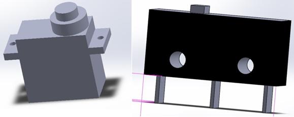
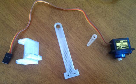
TowerPro SG90 9G Mini Servo with Accessories

Omron SS-5 Microswitch (not shown in picture)

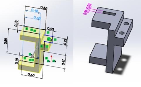
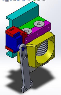
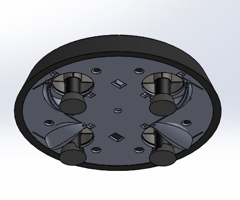
Servos mount (3D printed)

Servo arm (3d printed)

PARTS NEEDED

Male pins

Assembly:

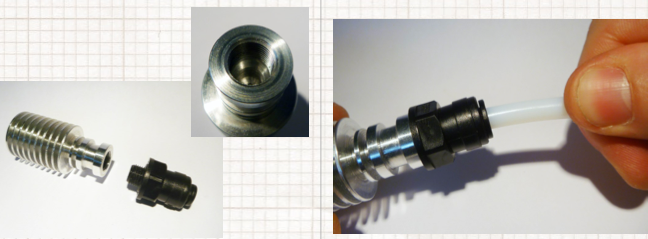
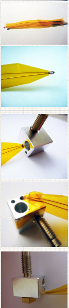
Servos mount needs to be sanded down in order for the servo to fit properly. The slot that was made for the servo wires was cut off further, for easier installation. Micro-switch is added to the bottom of the printed arm with a zip tie. Top of the printed arm has an opening that needed to be enlarged with the Dremel, in order to be able to connect to the servo gear. By now there should be two items to be connected together.  Combine both servo and printed arm, and use the small white arm (that came with the servo) into the servo gear. Use a small screw to keep in place.

In the Ramps shield, a jumper needs to be installed 5V to Vcc next to the reset button. This will activate the servo pins. Our current Ramps shield did not have pins for servos or for 5v to Vcc, so some soldering was done.
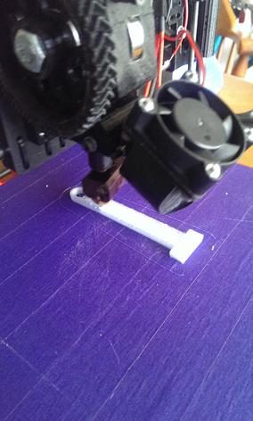
PINS

Installing:

With hardware assembled, the completed part is attached to the hotend mounts/x-carriage. A drill was used to make opening for the screws that will hold the servo mount in place. After everything installed, we need to connect to the servo pin 0 and connect the servo into the Ramps shield. With hardware installed, we need to go to the Marlin Firmware to enabled auto leveling

Firmware:

In configuration.h file:

#define min_software_endstops true // If true, axis won’t move to coordinates less than HOME_POS.

Was changed from true to false, this will not allow firmware to move any axis go below zero.

Scroll back down to Auto Bed Leveling section, uncomment:

//#define ENABLE_AUTO_BED_LEVELING

Scroll down and skip (for now):

#define X_PROBE_OFFSET_FROM_EXTRUDER -25
#define Y_PROBE_OFFSET_FROM_EXTRUDER -29
#define Z_PROBE_OFFSET_FROM_EXTRUDER -12.35

(These values will change, these need to be measured. Every printer will have its own unique offset numbers)

Change the travel speed, (8000 is too high and might cause skipping problems), choose from 4000-6000. I choose 4000.

#define XY_TRAVEL_SPEED 8000         // X and Y axis travel speed between probes, in mm/min

For now, I pass the Auto Leveling section and go to R/C Servo support section:

Uncomment the following lines:

//#define NUM_SERVOS 3 // Servo index starts with 0 for M280 command
//#define SERVO_ENDSTOPS {-1, -1, 0} // Servo index for X, Y, Z. Disable with -1
//#define SERVO_ENDSTOP_ANGLES {0, 0, 0, 0, 70, 0} // X, Y, Z Axis Extend and Retract angles


Servo number was changed from 3 to 1. In SERVO_ENDSTOPS the first two values are “-1” (disable) with the third being “0” enable). SERVO_ENDSTOP_ ANGLES will later be changed to an appropriate angle of extraction and retraction

I encountered twitching problems while printing; servo printed arm would twitch when printing which might cause the servo to malfunction after time. To avoid this problem this line was uncomment:

In the configuration.h file

//#define PROBE_SERVO_DEACTIVATION_DELAY 300

Now the angles for servos will be adjusted using Pronterface with command:

M280 P0 S160

(This command is telling the printer to extend servo 0 (P0) to an angle of 160 degrees (S160)).

If everything is installed appropriately, the printed arm will extend. Changing the value of “S” until the micro-switch is parallel with the print bed. If it’s not parallel the switch will never activate and it crash into the bed. Do the same for the retraction angle; make sure that the angle is wide enough to clear from any objects while printing.

Go back to Configuration.h file, and add your new angles:

#define SERVO_ENDSTOP_ANGLES {0,0, 0,0, 70,0} // X,Y,Z Axis Extend and Retract angles

The 3rd pair (Z-axis endstop) was change and new values were added (Z Axis Extend and Retract angles). Then load to Ramps. Now the probe/extruder offsets needs to be defined. An arbitrary point was selected on the bed and marked. Somewhere in the middle works well, but it’s not important. Using the X, Y, and Z controls on Pronterface, positions the hotend so that it is just touching the mark. Slide a piece of paper between hotend nozzle and bed should be barely able to clear.

Zero all the axes with command:

G92 X0 Y0 Z0

(This command will temporarily set the hotend’s current location as the zero point for all three axes)

After the command, raise the hotend until there is sufficient room to extend servo printed arm with micro-switch (which is now your z-axis probe). To extend the Z-probe use the M401 command.

With the z-probe extended, Pronterface was used to place the micros-witch trigger right on top of the mark on the bed. Z-probe is lowered until the Z-end stop is triggered; check if endstops were triggered command M119.  Once verified that the Z-end stop has barely been triggered, use M114 to read the current position of the hotend, and record the values. You should have one value for X, one for Y, and one for Z.

Multiply the values by -1 to reverse the sign.

Back in Configuration.h, change the probe offset values to your new values

Example: (old values)

#define X_PROBE_OFFSET_FROM_EXTRUDER -20
#define Y_PROBE_OFFSET_FROM_EXTRUDER -24
#define Z_PROBE_OFFSET_FROM_EXTRUDER -10

Replace the values with your new sign-reversed values.

#define X_PROBE_OFFSET_FROM_EXTRUDER 30
#define Y_PROBE_OFFSET_FROM_EXTRUDER -2
#define Z_PROBE_OFFSET_FROM_EXTRUDER -9

The last things to change are probing positions on the bed:

Initially were set as:

#define LEFT_PROBE_BED_POSITION 50
#define RIGHT_PROBE_BED_POSITION 150
#define BACK_PROBE_BED_POSITION 150
#define FRONT_PROBE_BED_POSITION 50

These will need to be changed in order to probe farther out. Farther out the better the plane calculation will be. Caution needs to be taken to make sure that there will be no issues with clearance with any other objects around the x-carriage and auto leveling parts and make sure that the probe is within the bed. Ramps 1.4 will be uploaded with all new changes.

Use command G29 to run the auto-level. But before you do, you need to home all positions by either clicking home button on Pronterface or by using G28 before running the G29. Click on the link below to see auto bed leveling in action.

https://www.youtube.com/watch?v=I3SBSFOKj5w

Gel Point Test Plan Excuted

By Omair Tariq

Purpose

The purpose of this test plan was to carry out the test plan here and determine the gel point of 1% Agarose gel. This test plan would also serve to verify the specification already provided by the manufacturer of the powder.

Equipment needed

Equipment

Quantity

Spatula

1

Mesuring balance accurate to a 100th of a gram

1

900 Watt Hot Plate

1

100 ml beaker

1

50 ml graduated cylinder

1

Mercury-in-glass thermometer  (Range: 0oC-110oC)

1

Agarose gel Type A0169 by Sigma Aldrich

See Table 2

Distilled water

See Table 2

Safety Goggles

1 per person

Latex Gloves

1 per person

Table 1. Equipment needed for Gel Point Testing

The amount of Agarose gel and Distilled water is to be determined by the desired gel concentration. 

Percent Gel Desired (concentration) =100 x  (Amount of Agarose in grams) / (Amount of water in milliliters)

Concentration

Agarose Gel Type A0169  (± 0.05g) Distilled water ( ± 0.1 ml)

1%

0.50 g

50.0 ml

2 %

1 g

50.0 ml

5 %

2.5 g

50.0 ml

And so on…


Table 2.  Amount of agarose gel powder and water required to produce desired gel concentration for 3D bioprinter

For the purpose of the bio-printer the amount of distilled water is to be limited to 50.0 ml since the extruder is a 60 ml syringe. The maximum amount of water is limited to 50 ml rather than 60 ml to avoid spilling of the gel and consequently, the waste of valuable gel mixture.

Test Plan Instructions


Note: This test plan can be carried out to determine the gelling point of any concentration of gel. 1 % gel concentration was chosen for the purpose of our bioprinter.

1.Put a 100 ml beaker on the weighing balance. This was not done due to the limitations of our weighing balance which had a maximum limit of 20 grams. Instead, a small plastic dish was used to weigh the powder.


 Untitled-1

2.Zero the balance so that the weight of the beaker does not hinder measurements.

Untitled-2

Use a clean spatula to put 0.50 grams of Agarose gel Type A0169 powder by Sigma Aldrich into the beaker. 


 Untitled-3

4.Measure out 50 ml of distilled water using a graduating cylinder.


 Untitled-4

5.Pour the 50 ml of distilled water into the beaker containing the 0.50 grams of Agarose powder. 

Untitled-5 

6.Measure the weight of the solution using a measuring balance. It should weigh about 51 grams. This was not done due to our weighing balance having a maximum weight limit of 20 grams.

7.Mix the solution using a Mercury-in-Glass Thermometer or a spatula.


8. Put the beaker containing the mixture from Step 4 onto a hot plate.


 Untitled-6


 9.Bring the solution to a boil and let it boil for 5 minutes.


 Untitled-7

10.At the same time, place the graduating cylinder filled with water on the hot plate.


 Untitled-8


 11.Reweigh the solution after boiling.

12.Add enough hot water from the graduating cylinder, if necessary, to bring the total weight of the solution to 51 grams.

13.Allow the mixture to cool. Mix the solution continuously until the solution reaches a temperature of 50oC. At this point, further mixing might lead to problems in accurately determining the gelling temperature of the solution.   Observe the viscosity of the solution every 10o C until the solution reaches a temperature of 40oC.  Once the solution has reached a temperature of 40oC, or when the solution starts to gel, the viscosity of the solution must be observed every 1oC.

14.The viscosity is to observed using the following steps:
Take a small amount of solution on the spatula,
Raise the spatula about 12 inches above the beaker.
Carefully, drop the solution by tilting the spatula.


This happened when the solution was at a temperature of 36oC. Therefore, it was determined that 1 % agarose gel has a gel point of 36oC. At the gelling point, the solution turned rubbery. When it was attempted to mix the gel at the gel point, the gel broke into smaller pieces. The smaller pieces did not merge after sometime as they would if the gel was still a solution. This would not happen if the mixture were still a solution, thereby proving that the gelling point was reached.


Untitled-9 

Untitled-10


The solution gelled at 36oC


The gel structure breaks into small solid pieces if mixed at a temperature below the gelling temperature


This test plan can be seen carried out here.


Conclusion


Through this test plan, it was determined that 1% agarose gel has a gelling point of 36 oC. This test also verified the values that were provided by the manufacturer of agarose powder.  Therefore, the extruder temperature will be maintained at 38oC to ensure smooth extrusion of the gel. 


Building the UFO 1.02 (Code Name: George Michael)

By Tuan Vo, Project Manager

For this new build, we are shooting for a perfect looking UFO with all the right curves and moves.  To do this, Juan Montano uses his extreme Solid Works skills to import the skills to create a working prototype of this UFO.  From the dimensions of a 2D picture of the UFO into the third dimension.  From this 3D model, Tuan Vo, the project manager, will use his extreme 3D printing prototype, we will be making a mold from which different material models can be created to produce great looking UFOs. 

1 

2

3


4

Tuan Vo’s 3D printer has a 200mm by 200mm base.  The UFO is too big to print out in once piece, so we will have to slice the model into four quarters.  The model consists of a shell, a bottom plate, adjustable vents, and feet.

5

A quarter of the shell.  The fan mounts directly into this shell.

6

The base will also be 3D printed with slots to mount two new vents.  The base will also be 3D printed and all the battery and electronics will mount on this base.

7 10

This is the new vent/air deflector.  This will create a clockwise torque by forcing air in a desired direction.  For more information, see Juan Montano’s blog on air vents.

9 

Because of time constraints, we won’t have enough time to make a good mold of this UFO and make any reliable casts.  Instead, we will be printing the UFO at 0.2 infill and use PLA 3D printed parts for the whole UFO.  Infill of 0.2 means the prototype will only be 20 percent of a solid model.  The base holds all the electronics inside its compartment.  The foot at the bottom of the motor is necessary because the bottom of the motor has exposed mechanical compartment.  After we glued the top shell together, it was very lightweight and has enough support for actual flight.  To secure the pieces together, we use epoxy bonds and superglue.  The electrical components are secured using zip ties. The bottom and top piece will be secured together either by zip ties or steel safety wire.

Advantages of using 3D printed parts Disadvantages
Precise and aesthetically pleasing Slightly heavier
Able to print intricate designs Need a 3D printer
Plastic can be used to make mold later on Production takes a long time
Sturdy depending on infill level 3D printed parts might not glue together perfectly


For later generations of UFO, we will be looking to make a mold of the model and use lighter material such as carbon fiber or fiberglass.

In the end, we have this:

10 11

12 13


Note that from the bottom, we are only using two vents.  This is because to counteract the torque, we only need two.  Also we want to simulate as close as possible the opposing pairs of CW and CCW spinning fans in a quad copter setup.  From the top down we observe the fan blades spinning CCW; this makes the body of the fan, and the whole UFO, want to spin CW.  We negate this by forcing the air in such a way that will add a CCW force to the whole UFO.

The electronic setup is not included in this picture because this UFO technology is highly classified, and not because we forgot to take pictures before closing the two compartments together. 

The end result of this build is not that much heavier than the last generation’s UFO Abducted.  We will want to eliminate as much material as we can in Solid Works by making walls thinner and printing at 0.1 infill should be more than enough to create a lightweight plastic model that will lift off at the desired amount of thrust.  Although this prototype, the George Michael, feels heavy, most of that weight comes from the battery and the fans themselves.  We achieved liftoff on first run.  Observe in the video.

https://www.youtube.com/watch?v=_Mr3EYFReeo


Building the UFO 1.01 (Code Name: Buster)

By Tuan Vo, Project Manager

First attempt.

For our build, we will be using a foam body sandwiched between two stiff and flat carbon fiber donuts.  We will use a clay mold to form a carbon fiber shell top piece that will give the UFO its characteristic dome shape.  The fans mount into the top donut piece, not the dome shell. 

Here are some pictures from our build.

Model by Juan Montano.

1 Untitled-1

Below is a proposed picture of what was going to happen. 

 3

The foam will be carved out into a hollow cylinder.  We will cut out smaller CF circle on top and a bigger CF circle on the bottom.  Using a 55mm drill, we can cut the 4 holes on the top to mount the fans and four holes on the bottom of the bottom circle for the air outlet.  We can then cut the foam to whatever height we want, and we can also use a hot knife to cut out the slanted skirt that gives the UFO its characteristic look.

Below is the picture of the proposed clay mold we will be using for the top dome carbon fiber shell. After 30minutes of hand molding, we were able to come up with a rough figure.

 4

STOP!

During this build, we encountered several hard challenges and problems:

  1. Hand cutting a foam piece with a hot knife is extremely difficult.  The plastic is toxic and Tuan Vo had to use a respirator in order to cut it safely.  Also, foam is very unforgiving to mistakes and erroneous cuts.  After a lot of practice on a smaller foam piece, we decided that there was no way to make the foam look good even with great skill and precision.  The end product on the practice piece is a charred and uneven cylinder; it looks non-presentable and not very usable.
  2. Clay modeling, although easy to do, is not easy to create a perfect dome.  There are constantly holes and flat spots present through many forming.  The potential of clay could not be achieved due to lack of a spinning table and experience.  No matter how much time we put into it, we will not achieve a mold good enough to lay carbon fiber on. 
  3. The vent, although functional and adjustable, adds height to the UFO making it look very awkward. 

After much discussion and consideration, we decided to scrap this build and go for a new approach.  This build would work if we were preferred 1. Shorter build time 2. Less weight 3. Less design time while increasing cost and lowering aesthetic standards.

In the new build, UFO 1.02, we will be taking a more time consuming and precise approach in creating the UFO.

Wireless Remote Communication Using XBee Radios

By Jake Rice

The Remote Control

In order to meet the requirement of wireless communication between the UFO and the user, the UFO was equipped with an XBee radio. A remote control with 2 joysticks to enable the user to control the UFO was also equipped with an XBee radio. The joysticks control 2 10k-ohm potentiometers, with one for the vertical axis and one for the horizontal axis. Since the ADC has a maximum input voltage of 1.2 volts and the XBee reference voltage is 3.3 volts, a 22k-ohm resistor was placed in series with each potentiometer to limit the maximum input voltage to 1 volt.

XCTU Remote Configuration copy

Configuring the XBees

The two XBee radios were then configured to communicate with each other using XCTU. In order to communicate, two XBees must each have their destination address match the serial number of the other XBee. The UFO XBee must be set as a coordinator and the remote control XBEE must be set as an end device. To allow the XBee on the UFO to communicate serially with the Arduino, both XBees must be set to API (Application Program Interface) mode. IO pins 0-3 on the remote control XBee must be set to ADC mode to be used as inputs for the joysticks.

 XBee Data

While the two XBEEs are communicating in API mode, the remote XBee sends the UFO XBee packets of data called frames. The length of the frame depends on the amount of data being sent, and with 4 inputs the remote XBee sends frames of 20 bytes. The first byte of the frame is always the start delimiter 0x7E, which is used to determine where each frame begins. Bytes 12-19 contain the data from the ADC inputs on the remote.

XCTU Frames Being Received copy

Interpreting the XBee Data

In order to isolate the potentiometer values from the incoming frame, the Arduino program waits until an entire frame’s worth of data (20 bytes) has been received. It then checks to make sure the first byte of the frame is the start delimiter (0x7E). Then, the program skips to byte 12, where the input data begins. Each potentiometer reading is represented by 2 bytes, high followed by low. The program multiplies the high byte of each reading by 256 and then adds the low byte to store each reading in a single variable.

Testing the Remote Control

As a test of the remote’s ability to control the speed of the UFO’s fans, the Arduino program was configured to read the vertical position of the bottom joystick. The range of possible values from that of the joystick’s neutral position to that of its highest position were mapped to the range of fan speeds from 0% to 100% of maximum thrust. The UFO was secured in place and both the UFO and the remote control were turned on. As the user moved the joystick up, the speed of the fans increased accordingly.

Implementing the Air Ducts

By Juan Montano

Hello all, this study was made to determine if the air duct would be able to resolve our issue with having fans rotating in one direction.

First of all, we would like to see how our fan performs as of now. Below, you would see the fan blades that we currently have:

1

Now, we will use SolidWorks to determine the airflow:

2 

3

As seen above, we have airflow going down, through the fan, and out as a vortex. The air flows like an upside down whirlwind, which would turn into a problem if there was another fan spinning the same direction. Let’s see what happens with two fans flowing the same direction:

4

We see some turbulence in between the two fans.

Here is another example:

5

Here we can see more clearly that there is airflow going upward instead of just straight down, which will be a problem.

Next we see how the airflow goes using the air duct and the fan assembly:

6 

7

Our fan model and our air duct model. Put together we have:

8

Here is the airflow:

9

The airflow seems to be more stabilized now, however, we want to have some control over yaw, and therefore we reposition the air ducts like so:

 10


11

We see that it will behave ok. Still see some concerns in between the two fans however, that would be manipulated to try to get yaw control. We redo the simulation using our SolidWorks model:

12 13

Here we see the UFO with some air flow. Here we note that the air curving back to the top of the bottom was due to the limited boundaries and high rotational speed of the fan. SolidWorks simulated these airflows inside a 3D box to decrease the amount of computation needed, therefore, we will pay no attention to those air flows.

14 15 

16  17

Here we see the UFO closer and see how airflows near the UFO. We do see some air flow that behaves awkwardly, but mostly this system would let air flow downwards as we would like.

Below we show the UFO with more airflows:

18

Thus we can expect an easier time to control the UFO flight and possibly also yaw.