Learn the basics on how to: Post to Github, Download from Github, and Upload Code to Arduino

By Tommy Sanchez

Typically instructions on posting repositories to Github can be a little confusing, the tutorial below can be used as a guide to hopefully get you posting quickly and without the confusion. The tutorial also shows how to go about downloading a Github file from any public repository. It’s useful to understand how to use Github, as robot communication code for Arxterra can be found on Github.

The Arxterra Gitub page is: https://github.com/arxterra. If you don’t know how to upload the code to Arduino this tutorial also gives a simple guide on how to do so.

Attachment Link:
GithubArduinoTutorial


Initial Implementation of Arxterra Android App

By Matthew Clegg – Computer & Control Systems

With the final model of Spiderbot finally up and somewhat running, coding for communication between Spiderbot and the Arxterra control panel, via the Arxterra Android App has gone underway. With help from Tommy Sanchez of Robot Company’s MC3, I have managed to implement the code to enable communication with the control panel.

The following link is a video of basic movements available on the Arxterra control panel as applied to Spiderbot:

http://youtu.be/x4c4ajhPN9c

Prior to the time of recording, one of Spiderbot’s legs twisted so Spiderbot is placed on top of a toolbox for support, so movement has been shown in slow motion to give a better idea of what the actual Spiderbot movement is.

This link will lead to base instructions that were written to help with connection between the Arxterra Android App and Control Panel:

https://www.arxterra.com/news-and-events/

Temperature Control at the Tip & Base of the Syringe

By W. Mevan Fernando & Ali Etezadkhah

After pouring the agarose gel into the syringe it was found that the gel solidified at the base of the syringe  and at the tip of the needle due to lack of heating in those specific areas. Initially we decided to use 0.5Ω, 5W wire wound resistors to heat the base of the syringe. After running four of these resistors in series to increase the resistance and limit the amount of current passing through them, it was found that the resistors heated up enormously and would thus melt the plastic in the syringe. Below are current and power calculations we obtained for the four resistors in series. They were run using a 12V power supply.

Req = 0.5+0.5+0.5+0.5 = 2Ω

Pdissipated = I2Req = (62) (2) = 72W

Next, we wound a copper wire around four of the same resistors, also in series, with the resistors stacked on top of each other to test if the copper wire conducted enough heat to heat up the base of the syringe. Thermal tape was wrapped around the resistors and copper wire to stop heat from escaping. Even though the copper wire heated up, it didn’t carry enough heat after 2 inches of wire, preventing us from using this method as a solution to the problem.

Finally we decided to use two 330Ω resistors on the needle of the syringe and six 330Ω resistors on the base of the syringe both connected in parallel to provide heat to prevent the gel from solidifying. Thermal adhesive was used to glue the resistors on to the base and the needle. The 330Ω resistors heated up to around 40°C when we tested them which provide enough heating to solve our problem. The resistors were actually found be 328Ω once we measured them using a digital multi meter. Below are current and power calculations we obtained for the 330Ω resistors.

For the needle:

Req = (330*330)/(330+330) = 165 Ohms

 Pdissipated = I2Req = (0.0732) (165) = 0.873W

For base of Syringe:

 1/Req = 6* (1/330)

Req = 55 Ohms

Pdissipated = I2Req = (0.2182) (55) = 2.618W

Req measured using a digital multi meter for the needle and the base of the syringe came up to be 164 and 54.9 respectively. These values match the theoretical values we calculated above. The current draw from these resistors is quite low as well and thus would not damage our power supply in contrast to the wire wound resistors we used before.

The pictures below show the resistors placed on the needle and base of the syringe:

1 

Two 330 resistors glued to needle using thermal adhesive

2

Connecting wires soldered on to the resistors

3 

Thermal tape used to insulate the needle and keep leads from touching

4

Thermal tape used to insulate the base and keep leads from touching Six 330 resistors glued to base of syringe using thermal adhesive and soldered to connecting wires

5

Six 330 Ohm resistors glued to base of syringe using thermal adhesive and soldered to connecting wires

6

Needle connected to syringe and placed in the extruder

Budget Report

By Mason Nguyen, Project Manager

For a project, it is important to have well prepared detailed budgets cost in order to meet its goals and objectives. Detailed budgets will be included with the name of the item, item quantity, production location, shipping cost and total cost. Here is our final budget report.

Untitled-1

Following from the presented mission objective budget that was stated here (https://www.arxterra.com/mission-objective/), our team managed and maintained the budget within $500 range. In comparison to previous projects, our budget seems to be the lowest because we used an ADK board where it has a built in USB slot. Link to ADK board (https://www.arxterra.com/hexapod-adk-board/)  

However, for the Arduino Uno it does not have a USB slot so the user needs to buy another board that has a USB slot and connect it them together.  In addition, the Arduino Uno does not provide enough space to connect all 18 pins for the servos. It requires the user to use two ADA fruit servo shields to connect all the pins together.  Our team budget could have been less than $500 since we only needed 18 servos to operate the hexapod but we added an additional servo as a phone holder to observe and scan the area. 

How to replace metal gears and burnt circuit board from broken servos

By Tien Dang

 Introduction
During the project (hexapod), we broke total of four servos. After observation and analysis from the broken servos, we able to detect and identify two problems of how the servos were broke down, while the servos are running. First problem we encountered is overload in power, and the second problem is overload in weight.  So we took some time looking inside of the broken servos and found few solutions way to fix them.

What does inside of a servo look like?
Servos usually contain three parts (metal grinding gears, motor and circuit board)

figure 1 

Figure 1: Take apart servo with a screwdriver

figure 2 

Figure 2: Metal gears

figure 3

Figure 3: Motor and circuit board

How to fix broken servos?
To detect which problem servo met, we connected the servo to the board as we testing the servo.

  1. Power overload

This problem is usually meet when we first buy the servo and test right away without adjust the voltage to 6V or limit the current that goes by the servo.

figure 4

Figure 4: Circuit board inside the servo

For the power problem, three cables (black, white, red) will usually falling off from the soldering node or the chip is tanned. If the soldering parts are failing off, simply re-soldering it, if the chip is burnt, we have no choice but to replace the whole board (use the broken gear servos to exchange the board)

2. Weight overload 

This problem usually occurs when the team is testing the hexapod movements (forward and backward). The weight distribution usually does not equal for each legs, all of the weight will be putted on the back legs (which simply cannot create enough force to push the whole body moving forward). This will result into two problems. One is current over-drain, and the other is broken gears metal.

figure 5

Figure 5: Broken gear metal

For the current over-drain problem, we can repair it by using the same methods as power overload. For the broken gear metal, we need to replace the gear. We can buy the new metal gears online at the website http://www.amain.com/advanced_search_result.php?keywords=metal+gear&x=0&y=0. Then we can exchange the broken gear with the new ones. Instead of paying $12.50 to buy a new servo, this method will save a lot of money since one metal gear only cost $0.99 up to $4.99 compared to $12.99.

Conclusion

After looking inside four broken servos, I was able to exchange metal gears and burnt board for two of the servos. They are working and running smooth like a brand new servo. In case if we stumbled into this problem again while demoing the project, I will be able to dismantle the servo apart less than 5 minutes and exchange the broken parts without taking the whole hexapod apart (like we did from beginning). Save time and money!

Here is the picture that I replaced and exchanged metal gear without take apart or re-wiring the robot.

figure 6

Figure 6: Exchanging the broken metal gear for one of the leg.

figure 7 

Figure 7: Broken metal gear in middle leg’s servo 

Casting the parts

By Vinh Kim, 3D model and manufacturing

 figure 1

Figure 1: Here we will be using Smooth-Cast 300.

 figure 2

Figure 2: I used rice to measure the volume or you could go online at http://www.smooth-on.com/tools.php to use a Material Calculators “How much liquid plastic do I need?”

figure 3 

Figure 3: Using the resin molding Smooth-Cast 300, we will be mixing .55 oz for cup A in one and .55 oz for cup B. During the mixing process, make sure to pour the liquid from cup A into cup B and blend it fast (the resin will harden in 3 minutes so make sure to mix it fast) and carefully pour the combined mixture into the rubber.

At this time, the resin will turn white, so let it cool down for about 15 to 30 minutes than take it apart. Now, you have to wait about 10 to 14 more hours, before the casted parts can be machined.

figure 4

Figure 4: Casting done.


Cost Update

By Kristine Abatay – Project Manager

The following figure is a table of the total amount spent in creating the final model for Spiderbot:

Blog19_image1

Two total values are provided in the far right columns. The orange column projects the total amount that was spent in completing the overall project. The green column excludes any costs spent on material that was a result of experimentation. For example, the initial mold that was created for Spiderbot’s tibia piece was not used for the final tibia pieces, so its cost was removed from the final green column total. The same goes for some of the costs included in the orange column for casting resin material. There are three breakout boards included in the orange column costs because one of the boards was damaged, as mentioned in a previous blog post.

The items that are listed with two prices, separated by a backslash, indicate that two separate totals were paid for those components. In the case of the casting resin, our 3D modeling and manufacturing member, Simon Abatay, managed to find coupons and deals, so those materials purchased in-store were much cheaper in price. This route of purchasing smaller containers of the material in-store, was taken because purchasing everything in bulk online would have been too expensive and would have resulted in too much excess material.

The total cost came out to be much larger than expected (the expected total was somewhere in the $600 range), but many things were learned in doing so. Much more money was spent in the silicone mold maker material compared to last semester because the pieces used in this semester’s Spiderbot were more three-dimensional and voluminous by nature, so naturally, more material was required. An innovative method for producing casted pieces with less material was also found because so much money was spent to fund the experimentation portion of manufacturing, so maybe this grand, albeit scary, total was a good thing.  


Arxterra Coding

 By Chau To

  • Introduction:

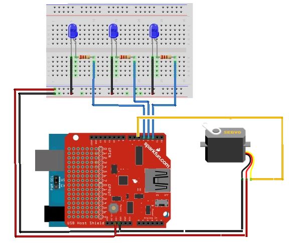
This blog post will introduce how to code and connect the Arxterra control panel into the Android phone. The Android phone that the Hexapod will use is to connect the Arduino ADK via the USB port. In order to link between the Android phone and the ADK, the user needs to download the adb.h library. Please contact the instructor or the division manager for download link.

  • Arxterra command byte:

Basically, the Arxterra control panel will send the command to the Android phone and from through the phone; it will communicate with the ADK via the USB port. The command from Arxterra is 5 byte (the last 5 byte of the 16 byte command series). It’s stored in the array called “data”. This is the list of the byte that the Arxterra sent out; the “xx” means that these bytes will change every time the user presses the button.

figure 2

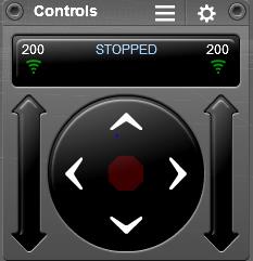
MOVEMENT CONTROLLER:

Forward:         01 01 xx 01 xx

Turn Right:      01 01 xx 02 xx

Backward:       01 02 xx 02 xx

Turn Left:        01 02 xx 01 xx

NOTE: This data only valid when the user presses stop between each command. For example, if user wants to turn right after walking forward, they have to press the stop button (the middle button).

figure 3

CAMERA CONTROLLER:

Left:                02 00 xx 00 xx

Right:              02 00 xx 00 xx

Hexapod does not use camera controller tilt up and tilt down, but the concept is very similar.

  • Coding:

The 1st byte data[0] is the command ID. Each controller will have a different command ID. Movement is data[0] = 01, Camera is data[0] = 02. So, we can compare the value of the command ID to control the robot.

The next step is to compare the 2nd value of the array data[1]. For movement, data[1] of forward and right turn in equals, and data[1] of backward and left turn is equal. Therefore, we will continue to compare the 4th value of data[]. The data[3] will be compared to decide that what movement the robot will need. With a couple of if…else statement, we can determine the action of the robot.

The data [2] and data[4] is varied overtimes because Arxterra was initially designed for the ROVER, and those byte were to control the speed of the DC motor. So do not worry about those bytes!!

Remember that you have to press stop before switching to a new command.

For CAMERA controller, the command ID is data [0] = 02. The third byte data[2] and the fifth byte data[4] is actually the angle when you convert from HEX to int.

  • Custom Command:

Since the Hexapod team this semester uses only 1 servo to control the camera (turn the camera left or right), we decided to create a custom command. The custom command is a very powerful tool to add a new desired controller. The custom command is provided on the Android Arxterra Apps on the phone. When the custom command is created, it will appear on the Arxterra website controller.

The custom Camera that I created will have a command ID of 0x04, initial value is 0, maximum value is 40 and minimum value is -40. Each increment by 1, the servo will move 2 degrees.

 figure 4

This is the Sample Code for the Arxterra testing:

#include <SPI.h>

#include <Adb.h>

#define FALSE 0

#define TRUE  1

// Commands to Numeric Value Mapping

//               Data[0] =   CMD TYPE | Qual

//                        bit  7654321   0     

#define MOV         0x01   // 0000000   1       

#define CHOICE      0x02   // 0000001   0                 

#define CAMERA      0x40

// Adb connection.

Connection * connection;   // the connection variable holds a pointer (i.e. an address) to a variable of data type Connection

// Event handler for the shell connection.

void adbEventHandler(Connection * connection, adb_eventType event, uint16_t length, uint8_t * data)    // declared void in version 1.00

{

  // Serial.print(“adbEventHandler”);

  // Data packets contain two bytes, one for each servo, in the range of [0..180]

  if (event == ADB_CONNECTION_RECEIVE)

  {

    Serial.print(“rover received command “);

    uint8_t cmd = data[0];

    uint8_t cmd2 = data[1];

    uint8_t cmd3 = data[3];

    uint8_t cmd_cam = data[2];

      if (cmd == MOV) {

      Serial.println(”          MOVE “);

      if (cmd2 == MOV){

        Serial.println(”  Forward or Turn Right “);

        if (cmd3 == MOV){ Serial.println(”  Move Forward  “);}

        else if (cmd3 == CHOICE){ Serial.println(”  Turn Right  “);}

        else { Serial.println(”  Stand  “);}}

      else if (cmd2 == CHOICE) {

        Serial.println(”  Backward or Turn Left “);

        if (cmd3 == CHOICE){ Serial.println(”  Move Backward  “);}

        else if (cmd3 == MOV){ Serial.println(”  Turn Left  “);}

        else { Serial.println(”  Stand  “);}}

      else {Serial.println(”  Stand  “);}

    }

    else if (cmd == CAMERA) {

      Serial.println(”      CAMERA  “);

      int fone_ang = int(data[1]);

      if (fone_ang <= 40){

        int ang = 90 – fone_ang*2;

        Serial.print(“Angle: “);

        Serial.println(ang,DEC);}

      else{

        int ang = 90 + (255 – fone_ang)*2;

        Serial.print(“Angle: “);

        Serial.println(ang,DEC);}

    }

    else {Serial.println(”  Stand  “);}   

 }

}

void setup()

{

  Serial.begin(57600);

  Serial.print(“\r\nStart\n”);

   //init_servos();

   ADB::init();     // source of OSCOKIRQ error

  // Open an ADB stream to the phone’s shell. Auto-reconnect

  connection = ADB::addConnection(“tcp:4567”, true, adbEventHandler);

  // insure motors are off and turn off collisionDetection

  // stopMotors();

}

void loop()

{

  ADB::poll();

}

Upload and Open the Serial Monitor (Ctrl+Shift+M) to test it.

SPECIAL THANKS TO VINH KHOA TON and TOMMY SANCHEZ !!!

Sub and System Requirements

By Chau To and Elaine Doan

Design:

  1. To maximize the speed of the Hexapod in order to match Rover speed at 0.2002 m/s:
    1. The weight and the size of Hexapod will be determined using Solid works model and stress test simulation will be performed. https://www.arxterra.com/how-to-perform-a-stress-test/
  1. The length of Femur and Tibia of the leg will be calculated to maximize the ideal step size of the Hexapod, which is 4 inches.( Ideally, Hexapod will take 2 steps in 1 sec and in order to match 0.2002m/s or 7.8in/s, each step needs to be 4 inches).
  2. A prototype will be built to verify that the model can match the speed with Rover.

Servos:

  1. In order to maneuver over obstacles and travel in the forest like settings, Hexapod will require 3 servos for each leg. Eighteen servos will be needed for 6 legs of the Hexapod. Servo type is https://www.arxterra.com/current-draw/.
    1. Based on the weight and size of the design, the torque will be calculated for the Hexapod speed and determine servo type. https://www.arxterra.com/current-draw/
    2. Verification of servo study is here: https://www.arxterra.com/a-better-servo-powerhd-1501mg-analysis/.
  2. To observe the environment via Android phone’s camera, one servo controlling the phone holder will be used, which help the user to scan the area with the Android phone mounted onto Hexapod.
    1. The angle sweep for the phone “turn-servo” is ( https://www.arxterra.com/current-draw/). The phone holder prototype will be built and test to verify the total view from the Android phone’s camera.

Microcontroller and Servo Controller:

  1. For the communication between microcontroller and the Arxterra Control Panel, the Hexapod will use the Arduino ADK microcontroller, which has a USB host interface to connect with an Android phone. ADK board will have more memory (Flash Memory, SRAM, EEROM) than the standard UNO to perform the complex programming for Hexapod movement such as racing with the Rover and maneuver through objects. ADK board also had enough digital output pins to support for 19 servos required for the Hexapod.
    1. Verify specs of the Arduino ADK at:  http://arduino.cc/en/Main/ArduinoBoardADK#.UyZ2EvldUz0

 Communication:

  1. The wireless control of the Hexapod is through using an Android phone app called ArxRobot.
    1. Verify the Android phone’s compatibility to the ArxRobot app by contacting Arxterra.

Link to Arxterra compatibility (https://www.arxterra.com/android-phone-complications-with-arxterra-robot-application/)

Power:

  1. The battery will be using is LiPo 5A pack.
    1. Trade-off study will be conducted to determine the type of battery and safety purposes.
    2. Maximum current test will be performed on one servo to determine the total power of the battery.
    3. 12 servos will need to be run simultaneously to verify that the battery can handle the performance of the Hexapod.

Current testing is available at https://www.arxterra.com/current-draw/.

  1. For safety purposes, Hexapod will use a voltage regulator to prevent damaging the Arduino ADK, and burning twenty servos. It will maintain 6V input as well as a steady current supply to the boards and servos. 
    1. Use oscilloscope and Multimeter to look at the output voltage and current of the voltage regulator in order to test and verify the stability output from the voltage regulator. Link to Voltage Regulator is here https://www.arxterra.com/voltage-regulator/.

Link to Mission Objective is here https://www.arxterra.com/mission-objective/


Simple control of Arduino using Arxterra

By Vinh-Khoa Ton, Control and Image Processing

The purpose of this experiment is to access the Arxterra control panel and to operate an Arduino board using the Microbridge connection through an Android phone.

For information about the Microbridge connection between Android and Arduino, please visit this blog post:
https://www.arxterra.com/simple-control-of-an-arduino using-an Android-phone/

A quick demonstration:
https://www.youtube.com/watch?v=D_rMULcm6uc&feature=youtu.be

How to set it up:
Use the schematic

schematic

The LEDs are on pins 2, 3, and 4 and the servo is on pin 5. The USB Host Shield v2.0 was needed for communication between the Android phone and the Arduino Duemilanove ATMega328.

Upload the Arduino code to the board (provided at the end of this post).

Open the ArxRobot app on Android phone and set up the connection with Arxterra, use the Microbridge connection type (for detail instructions please see Tommy’s powerpoint here:

http://csulb.edu/~hill/ee400d/Lectures/12_Arxterra%20Login.pptx)

Connect the Android and Arduino using a micro-USB cable (the app should have a command “socket client connected”)

SocketClientScreenshot

In this example I created 3 custom commands (3 switches) to control 3 LEDs.

Log-in to Arxterra using the same credential that was used to connect to ArxRobot app.

Go to the control panel:

controlpanel

At this point, the connection should be established. If we move a LED switch, the corresponding LED should turn on/off accordingly. If we hit a move button, the servo should respond accordingly.

Conclusion:
This experiment serves an important part in building a solid foundation for the final connection between our robot and Arxterra. After we successfully grasp the concepts of the communication between Android and Arduino, we can proceed to replace the move servo function with more complex movements to suit our need. The only limitation of what it could do is our imagination.

Arduino Code:
https://github.com/kh0/Spring-2014-ROFIA/blob/master/ROFIACode/ArduinoControlWithArxterra