Bioprinter Extruder Design

By Ali Etezadkhah – Project Manager

When we started working on the Bioprinter, one of our main challenges was to redesign a new extruder mechanism.  While the idea of using a syringe and a linear actuator to dispense the printing gel was good, the execution needed much improvement.

The original extruder used a small syringe and a cheap linear actuator to dispense the printing material.  Since it is not possible to reload the extruder while printing, we decided to use a 60cc syringe as our extruder.  The larger volume allows us to print larger structures without worrying about running out of gel.  In addition, the large volume has a more stable temperature.  We use a 1% agarose gel as our printing medium. As such, 99% of the gel is made of water, which has a very high specific heat capacity (Properties of Water).

 Untitled-1

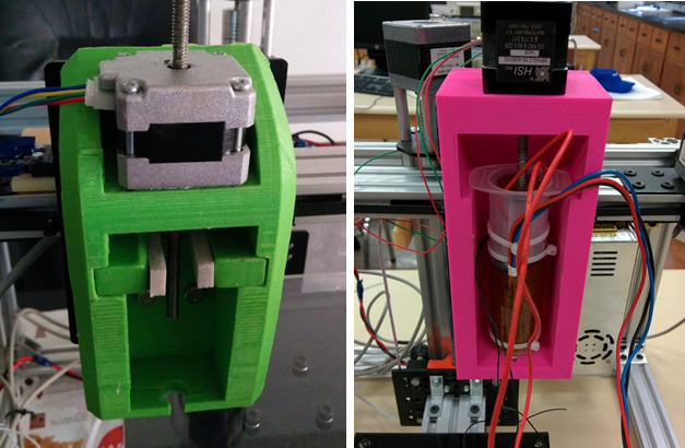
Old extruder on the left (green), new extruder on the right (pink)

The next challenge was to improve the precision of the extruder.  The original extruder used a cheap linear actuator to push the plunger into the syringe.  The linear actuator did not have enough torque to push the plunger precisely and extrude the printing material.  Luckily for us, Dr. Moussavi had already bought a precision linear actuator from Haydon Kerk company (Haydon Kerk).  Unlike the NEMA 17 stepper motors used to move the axes, this linear actuator is a NEMA 14.  Although smaller than the unit it replaces, it offers more torque according to the datasheet.

The linear actuator is a non-captive model, which means the lead screw is free to rotate and can be taken out of the unit.  The motor uses a rotating nut to extend or retract the lead screw, but the screw has to be fixed and cannot be allowed to rotate (Linear Actuators).  If the screw is free to spin, it will do so with the nut and it will not extend or retract.  We grinded one end of the lead screw into a chisel shape and designed an appropriate metal piece to mate with it and prevent it from turning.  This metal piece was epoxied to the plunger.

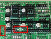
Originally we ran into a problem when we switched the actuators.  The new actuator would not stop where it was supposed to and the sound it made was abnormal after it reached that distance.  We tried to get help online and from the Maker Society, but were not able to troubleshoot our issue.  We contacted the manufacturer and found a very knowledgeable engineer who helped us fix the problem.  With his help we were able to find the problem and fix it.  It turned out the old actuator drew more current that the new unit.  We adjusted the maximum current by turning a small potentiometer on the stepper motor driver.  Once the adjustment was complete, the actuator started working correctly.

The original extruder used the bottom part of the plunger with a makeshift plastic piece to actuate it.  The plastic piece was too small to effectively spread the force of the actuator.  Also, there was no easy way to take the plunger out once the gel had been extruded.  To remove the plunger, first we had to use a metal rod to push the plunger through the tip of the syringe.  Once it was pushed up a few centimeters, a pair of needle nose pliers was used to pull it out of the syringe.  Our plunger has a piece of wire attached to it.  To remove the plunger, all we have to do is to pull on the wire loop and the plunger comes out easily.

fig

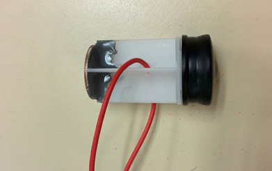
New plunger assembly

Much like regular 3D printers, our printer requires a precise extruder temperature to print effectively.  We decided to use a solid state sensor to monitor the extruder temperature.  The TMP36 is a precision, linear temperature sensor from Analog Devices (TMP36: Voltage Output Temperature Sensors).  It has a wide operating range of 2.7 to 5.5 volts and is calibrated directly in degrees Celsius.  The sensor was connected to an Arduino Uno programmed to monitor take a temperature reading every 2 seconds.  The output from the Arduino was monitor by a free application called PuTTY (PuTTY).

trans

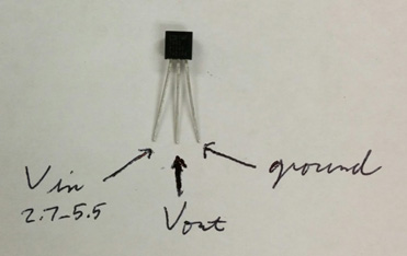
TMP36 temperature sensor

The temperature sensor was fine-tuned by comparing its reading with glass thermometer.  The Arduino code was adjusted so the reading from the TMP36 matched the reading from the thermometer.  Since the TMP36 is a linear device, it can be easily calibrated by adding or subtracting a constant from the reading.  Had we used a thermistor, we would have to create a lookup table and calibrating it would have been much harder.

syringe

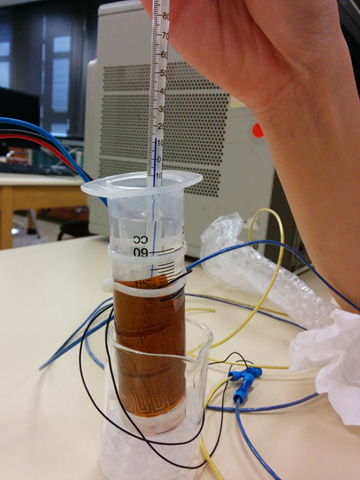
Matching the TMP36 output with a glass thermometer

The ideal extrusion temperature for our printing medium is around 33 to 35 degrees Celsius.  In this range, the gel is viscous enough to keep its shape with adequate cooling, but not too thick to cause extruder head blockages.  To keep the temperature in this range while printing, we used a flexible heater from Omega (Omega).  Since the heater runs on 115 VAC, we used the Arduino to control a solid state relay and provide power to the heater (SSR).

The default PWM frequency of the Arduino is around 490 Hz, much too high for our application.  The high frequency will cause the SSR to heat up and waste energy due to switching losses.  Since our target temperature is close to the ambient temperature, we don’t expect a lot of temperature fluctuation while printing. We wrote our own version of a low speed PWM routine on the Arduino.  The program never goes above 20% duty cycle and adjusts the duty cycle based on temperature differential between the extruder and the set point.

Once the extruder was ready, we designed a 3D printed structure for it.  The extruder housing was designed for easy access to the extruder.  The actuator sits on top of the housing and lead screw pushes down the plunger.  The first step was to model the syringe in SolidWorks.  Next, the extruder housing was designed and the two were mated in a SolidWorks assembly.  Once we were sure of the proper clearances and operation limits, the housing was printed.

extrude

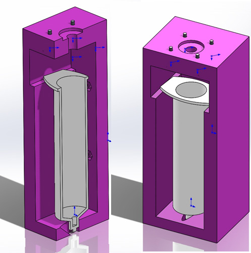
New extruder housing

 Works Cited

Haydon Kerk. (n.d.). Retrieved from http://www.haydonkerk.com/LinearActuatorProducts/StepperMotorLinearActuators/LinearActuatorsHybrid/Size14LinearActuator/tabid/77/Default.aspx

Linear Actuators. (n.d.). Retrieved from Wikipedia: http://en.wikipedia.org/wiki/Linear_actuator

Omega. (n.d.). Retrieved from http://www.omega.com/pptst/KHR_KHLV_KH.html

Properties of Water. (n.d.). Retrieved from Wikipedia: http://en.wikipedia.org/wiki/Properties_of_water#Heat_capacity_and_heats_of_vaporization_and_fusion

PuTTY. (n.d.). Retrieved from http://www.chiark.greenend.org.uk/~sgtatham/putty/download.html

SSR. (n.d.). Retrieved from http://www.amazon.com/Solid-State-Relay-24-380V-Control/dp/B0087ZTN08/ref=sr_1_5?ie=UTF8&qid=1398739255&sr=8-5&keywords=solid+state+relay

TMP36: Voltage Output Temperature Sensors. (n.d.). Retrieved from Analog Devices: http://www.analog.com/en/mems-sensors/digital-temperature-sensors/tmp36/products/product.html


System/Subsystem Design

by Suhyun Kim

System Block Diagram

block 

The image above provides an overview of how each component is linked together within the rover. 

Camera/Phone:
From a remote location, using the Arxterra interface we will be able to communicate via the phone and camera.  The camera will provide an image to the Arxterra interface.  Through the phone, we can use the interface to communicate with the microcontroller.

Microcontroller:
The microcontroller subsystem includes an Ardiuno Uno and a Motor Shield.  The Uno will be the bridge between the phone and the motor shield.  The motor shield is used to control the 2 motors and 2 servos on the rover.

Battery:
The rover will have several batteries.  One dedicated battery to power the microcontroller and one to power the motors and servos.  The batteries must provide enough power for all of these components until the end of the mission.

Motors/Servos:
The motors will drive the wheels.  The motors must provide enough torque to move and enough RPM to fulfill our speed requirement.  The servos must provide enough torque to pan and tilt and must provide a range of vision as described in the test plan.

Detailed Cost

By Maxwell Nguyen and Anthony Vo

The first link below provides the BOM for the standard RoSco as provided by Arxterra.  The second link sums the price of each part in order to provide a projected cost of the standard RoSco.

Bill of Materials:
Standard RoSco BOM

Standard RoSco Cost:
https://www.dropbox.com/s/kpw4iobx1h1ova2/standard%20rosco%20bom.xlsx

The link below is the projected cost of the rover taking into account of parts replacement.  This link provides a complete BOM, which includes parts description, quantity, price, and source.

New Rover BOM:
https://www.dropbox.com/s/439vaho8fhycdth/Rover%20Projected%20Cost%20new.xlsx

Task Descriptions

by Maxwell Nguyen

  • 1.      Trade off studies: 1 week

Compare different motors and servos.  Determine which motor and servo will best meet our subsystem requirements.


 2.      Test motor: 1 week
Test/record current draw and RPM of motors at different voltages.


 3.      Test Servo: 1 week
Test/record current draw of servo depending on required torque.  The required torque will be simulated by lifting an object.  Verify torque load of servo.

 4.      Mirror Study: 1 week
Test mirror functionality with phone camera.  Record a video with mirror in place at different angles.

 5.      Battery test: 1 week
Measure/record current and capacity of the battery.

 6.      H-Bridge Study1 week
Research and report the functionality and purpose of an H-bridge.  The new Adafruit Motor Shield comes with an H-bridge on board.  Research will be done on how to implement the H-bridge into the rover design.

 7.      Program testing:  1 weeks
Learn and write up a program to test servos and motor shield.  Coding will most likely be done in C++.

 8.      Motor shield test 1 week
Confirm that the motor shield is working properly by testing injunction with motors and servos.

 9.      Track research 2 weeks
New track design will be based on tank treads.  The goal will be to design tracks that can be printed as separate individual pieces.  The pieces will be able to attach to each other to create a single belt.

10.     Phone to Arxterra test:  1 week
Download and install Arxterra app onto the teams dedicated Samsung Galaxy S3.  Confirm that the phone can communicate to Arxterra and provide and image via phone camera.

11.     Arxterra to Arduino test:  1 week
Confirm that the Arxterra is communicating to the Arduino Uno.  Confirm that the Arxterra user interface can relay signals to the Arduino and Motor shield.

12.     Remodel Head:  2 weeks
Design a new head that will support the phone and allow for panning and mirror tilting.

13.     Print parts:  3 weeks
Send orders to manufacturing division to get parts printed

14.     Assemble Rover 1 week
Rover and track assembly will be done.  Some sanding and reshaping may be required if parts do not fit together.

15.      Conduct Test Plan: 2 weeks
Test and verify that rover can achieve the requirements laid out in the test plan.

Test Plan

By Suhyun Kim and Robert Licari

For our new design of Rover, we will do some tests such as electrical tests, software tests and functional tests. The electrical tests would be minor and basic tests, and software and functional tests would be main tests for our project.

Electrical Tests:  1 week duration
Electrical Tests will mainly include Current and Voltage Tests of battery, motor, servo converter and microcontroller. 9VDC motor supply and 9V UNO supply will be tested to ensure that the supplies are providing the proper amount of current and voltage required to power the rover.  Also, the two of DC motor and Servos will be tested for their current draw because all of motors are core parts in controlling the Rover.

   Test Type       Test sub-type
Battery 12VDC Motor Supply
  9V UNO Supply
Motor DC Motor (x2)
Servo Servo (micro)
Microcontroller Arduino Uno

Motor Shield


Software Tests: 1 week duration
On the Software Tests, we will test how applications of Arxterra are well connected to Arduino Uno and Control Panel. Also, we will check Image Processing parts. These tests would influence on how the Rover is exactly navigating through the course.  We will confirm that the Axterra interface can communicate through the phone with the microprocessor.

Test Type Description
Applications with Control Panel How applications are well connected to Control Panel
Control Panel with Arduino Uno How Control Panel are well connected to Arduino Uno


Functional Tests: 2 week duration
Functional Tests is our project’s main tests. It will include Speed Tests, Turn Tests, Pan Tests and Tilt Tests. In speed tests, we will do forward speed and backward speed tests on flat surface and natural surface. We will check that Rover can navigate like calculated speed on any surfaces, especially natural surface.  To navigate through designated course, the Rover has to turn left side and right side. Therefore, we will do 90 degrees left and 90 degrees right turn tests from forward (normal position). Pan tests will be same to turn tests. Also, because rover will have a mirror to secure views, we need tilt tests.  We will test 45 degrees upward tilt and downward tilt from normal position. 


Test Type Test sub-type Description Desired Results
Speed Tests Flat surface A 10 meter “dash” across a flat, smooth, surface.  


Calculated Speed @0.200277 m/s

  Natural surface A 10 meter “dash” across a natural, earthen, surface. (loose earth).
  Flat surface Test

(Reverse)

A 10 meter “dash” across a flat, smooth, surface backwards.
  Natural surface

(Reverse)

A 10 meter “dash” across a natural, earthen, surface. (loose earth) backwards.
Turn Tests Right Turn A 90 Degree Turn Right from Normal (Forward) Position  
  Left Turn A 90 Degree Turn Left from Normal (Forward) Position  
Pan Tests Pan Right A 90 Degree Pan Right from Normal (Forward) Position  
  Pan Left A 90 Degree Pan Left from Normal (Forward) Position  
Tilt Tests Shutdown A Test -45 Degrees from Normal (45 Degrees)  
  Normal A Test at 45 Degrees  
  Look-up A test +15 Degrees from Normal (45 Degrees)  
  Sky box A Test +45 Degrees from Normal (45 Degrees)  


Three Point Leveling

By Mustafa Alkhulaitit – Project Manager

Another minor upgrade that will be applied to the heat bed is what’s called “three point leveling”. The previous heat bed had what people uses on their 3D printers. The most common method used on heat beds is the four point leveling, which is simply having four bolts on each corner of the heat bed to mount it.

Fig1

This figure shows the positions for the bolts to mount the heat bed- “Four point Leveling”

There are few problems when it comes to using the four-point leveling such as over-constraint and complicating leveling procedure. To fix this issue, the three-point leveling is introduced and is beginning to spread among 3D printer users.

Advantages of 3-point leveling:

  1. High quality prints
  2. Reliable printing
  3. Increase of first layer adhesion

All of those advantages will help us meeting our requirements. All of those advantages depend on a leveled bed, which is a very important point when it comes to 3D printing.

The procedure depends on how many points of attachment are used to mount the bed. Three-point of attachment avoid the problem of over-constraint and simplifies leveling procedure. Three-point leveling uses a triangular pattern that can be seen in Fig.2. There will be only three bolts to mount down the bed instead of four.


For more information, please check: http://numbersixreprap.blogspot.com/2012/09/heated-bed-with-three-point-leveling.html


Construction Update 3.0

By Mustafa Alkhulaitit – Project Manager

The heat bed as mentioned in a previous blog post is remaining the same, except for minor upgrades. This blog post is going to cover the upgrades and work done on the heat bed. The first thing was changing the insulation material used in the original design. The insulation was no more than few pieces of cloth put together and taped with Kapton tape. The look was unprofessional and there was heat loss.

Fig1

The previous design is shown in Fig.1.

 To fix this, a rigid foam insulator is now used instead of the cloth. The insulation foam sheet was cut and cleaned for perfect fitting. Figures 2 and 3 show how insulation sheet and how machinery was used to have the perfect thickness.

Fig2

Fig3

The surface, as can be seen in Fig2, will reflect heat minimizing heat loss. Figures 4 and 5 show the final insulation sheet ready for implementation.

Fig4

Fig5


Construction Update 2.5

By Mustafa Alkhulaitit – Project Manager
and  Gregorios Rios – 3S modeling

 This a follow up to the previous blog posted. In this blog, I will be discussing in details how I got the LCD controller to work. As mentioned before, there were multiple issues associated with the LCD panel. This blog will be broken into different sections targeting the different issues.

 1.      Arduino IDE:
The first step is to make sure that the Arduino IDE is connected to the correct board. In our case, the board used is the “Arduino Mega 2560”

 fig1

The other step is to make sure that the serial port is the one that the board is connected to. If the COM port is different, there will be no connection between the board and the computer.

The bottom right corner of the Arduino IDE states the board that the COM port is communicating with.

 fig2

2.      Firmware:
By downloading the Marlin firmware, the default motherboard was “7” and needed to be changed to “33” which is the board we are using.

// 10 = Gen7 custom (Alfons3 Version) “https://github.com/Alfons3/Generation_7_Electronics”
// 11 = Gen7 v1.1, v1.2 = 11
// 12 = Gen7 v1.3
// 13 = Gen7 v1.4
// 3  = MEGA/RAMPS up to 1.2 = 3
// 33 = RAMPS 1.3 (Power outputs: Extruder, Bed, Fan)
// 34 = RAMPS 1.3 (Power outputs: Extruder0, Extruder1, Bed)
// 4  = Duemilanove w/ ATMega328P pin assignment
// 5  = Gen6
// 51 = Gen6 deluxe
// 6  = Sanguinololu < 1.2
// 62 = Sanguinololu 1.2 and above
// 63 = Melzi
// 7  = Ultimaker
// 71 = Ultimaker (Older electronics. Pre 1.5.4. This is rare)
// 8  = Teensylu
// 81 = Printrboard (AT90USB1286)
// 82 = Brainwave (AT90USB646)
// 9  = Gen3+
// 70 = Megatronics
// 90 = Alpha OMCA board
// 91 = Final OMCA board
// 301 = Rambo

#ifndef MOTHERBOARD
#define MOTHERBOARD 33  // 33 is for Ramps 1.3 and 1.4
#endif

 3.      Hardware:
Connection pins had to be soldered on the RAMPS 1.4 in order to establish connection between the LCD controller and the RAMPS 1.4.

 4.      Power Issue:
Another issue we’re facing is dealing with the power supply. The LCD controller won’t remain ON when we disconnect the PC connection to the board. After some research, it appeared that the RAMPS 1.4 is missing a diode that would make the LCD controller on without the PC connection.

Therefore, 1N4004 diode will be soldered on the RAMPS 1.4, and that will solve the power issue.

fig3

The middle indicated rectangle is where the diode going to be soldered.

5.      Conclusion:
Other than this, the LCD controller is a very neat feature that the printer is going to have. All of the other functions were verified like adjusting the axis, temperature, and the fans. After soldering the diode, the LCD controller will be a 100% working and ready to function without any issues.

Simple Control of an Arduino using an Android Phone

By Vinh-Khoa Ton, Control and Image Processing

The purpose of experiment is to become familiar with the way an Android phone communicates with an
Arduino board using MicroBridge, an Android Debug Bridge (ADB) implementation for microcontrollers.
[Insert Android-Arduino.jpeg]

How it works:
The ADB protocol can either create a new shell or use the existing shell on an Android phone to send commands, read debugging logs, and forward TCP ports and Unix sockets. The Android phone reads data from a port that Arduino is connected to through the ADB. When a connection is lost (the application crashes, the USB cable is unplugged, etc), MicroBridge will try to reconnect to the device upon redetection.

Compatibility:
MicroBridge is designed to work with Android phones with version 1.5 and above. The following phones are confirmed to be compatible: ZTE Blade, Nexus S, Samsung Galaxy S, HTC Desire HD, HTC Nexus One, and LG Eve. A quick demonstration:
http://youtu.be/cX8whgZkdzk

How to set it up:
Using the schematic

schematic

The LEDs are on pins 2, 3, and 4. The USB Host Shield v2.0 was needed for communication between the Android phone and the Arduino Duemilanove ATMega328.

Some prerequisites:
Download Android SDK at http://developer.android.com/sdk/index.html
Download ADB library at: https://code.google.com/p/microbridge/downloads/detail?name=MicroBridge-Arduino.zip&can=2&q
Download Arduino code and Android app at: https://github.com/mitchtech/android_adb_simple_digital_output

A look into the Arduino code:
void setup()
{
   int i;
   for (i = 0; i < LEDcount; i++)
{
   pinMode(i+2,OUTPUT); // Set pins as output
   LEDState[i] = 0; // Init state to 0
}
// Init serial port for debugging
Serial.begin(57600);
// Init the ADB subsystem.
ADB::init();
// Open an ADB stream to the phone’s shell. Auto-reconnect. Use any unused port number, eg:4568
   connection = ADB::addConnection(“tcp:4568”, true, adbEventHandler);
}
void loop()
{
// Poll the ADB subsystem.
ADB::poll();
}
void adbEventHandler(Connection * connection, adb_eventType event, uint16_t length, uint8_t * data)
{
// In this example Data packets contain three bytes: one for the state of each LED
if (event == ADB_CONNECTION_RECEIVE)
{
int i;
for (i = 0; i < LEDcount; i++)
{
   if(LEDState[i] != data[i])
   {
    digitalWrite(i+2, data[i]); // Change the state of LED
    Serial.println(data[i],DEC); // Output debugging to serial
    LEDState[i] = data[i]; // Store the State of LED
   }
  }
 }
}

We need to create a connection to the ADB streams and receive events when connecting, disconnecting, or receiving data. We initialize the ADB in the Setup function by calling “ADB::init();”.


In the Loop method, we must sequentially poll the ADB layer by calling “ADB::poll();”

These 2 calls are the minimum requirements for establishing and maintaining a connection to our Android phone. Next, we want to open a connection with the phone by calling “connection = ADB::addConnection(“tcp:4568”, true, adbEventHandler);”. The first parameter “tcp:4568” forwards local TCP port to the Arduino. The second parameter “true” indicates whether the reconnection should be handled automatically. The third parameter is a callback method which functions as an event handler, which defines what events need to be triggered. We need to implement the event handler function to receive data from the shell. This function has the following parameters: connection, adb event, payload length, and payload data. In this example, we are trying to read command data from the Android phone to control the Arduino so we need to specify the “event == ADB_CONNECTION_RECEIVE”. In this example the data package contains 3 bytes according to 3 LEDs outputs. The nested code in the if statement determines which LED lights up.

Conclusion:
The MicroBridge is a simple solution that allows communication between an Android phone and an Arduino board. With this experiment, we take a first step in getting familiar with the ADB protocol. This allows us to expand our Arduino projects with more capabilities such as remote control of our robots with a friendly user interface instead of having to upload the code manually, or utilizing the built-in gyroscope, camera, and accelerometer of the Android phone for external sensors for our robots.

Sources:
http://mitchtech.net/android-arduino-usb-host-simple-digital-output/

Polyfuse Testing and Implementation

By Kevin Huynh, Project Manager / Computer Systems and Software

Objective:
The first test will verify whether or not the servos used will be protected from drawing too much current when they stall. The current level that will be considered dangerous for  the Power HD 1501MG servo is the stall current listed in the datasheet (2.3 A at 4.8 V). The second test will check how long it takes for the polyfuse to trip at its rated trip current and how much leakage current there is.

Test Materials:
1. Arduino MEGA 2560
2. Power HD 1501MG
3. 06R120BU Littelfuse Polyfuse
4. UBEC-5A-HV DC-DC regulator
5. Extech EX330 Digital Multimeter
6. 7.5 V 2.4 A Wall Power Supply
7. DC Bench Power Supply
8. Pliers

First Test Setup:
testSchematic1

First Test Procedure:
1. Set the circuit up as shown in the setup section. First without the polyfuse.
2. Choose a servo horn to place on the servo, the servo horn used for this test was the four point star.
3. Keep the servo from rotating the horn using the pliers.
4. Use either an Arduino program or the Robot Poser program (Biped) to control the servo. If using an Arduino program, have the servo continuously rotate between two points.
Sample code for rotating a servo can be found here: http://arduino.cc/en/Tutorial/sweep
If using the Robot Poser program, use the sliders to change the servo angle.
5. Record the current measured on the multimeter, then repeat with the polyfuse in place.

First Test Results:
Before connecting the polyfuse in between the UBEC and the servo, the highest current was approximately 2.25 A for a brief moment, then consistently about 1.8 A in later tests. While the stall current is not at the level specified in the datasheet for the Power HD 1501MG, the temperature seemed to increase slightly.
With the polyfuse, the highest current value achieved during the test was approximately 1.1 A, which is very close to the rated holding current of the polyfuse. Since 1.1 A is well below the stalling current found in the previous test and the datasheet, the current is at a relatively safe level. What was unexpected was that the polyfuse acted similarly to a constant current limiter, with the hold current being the limit.

Second Test Setup:
testSchematic2

Second Test Procedure:
1. Set the circuit up as shown in the setup section.
2. Set the voltage level of the power supply to the output voltage of your regulator (if applicable).
3. Increase the current to the rated trip current of the polyfuse and record the time it takes for the polyfuse to trip.

Second Test Results:
There were two tests conducted because of the results found in the first test. One test was used to find the trip time of the polyfuse at 2 A, the other was used to find the trip time of the polyfuse at 1.8 A. The trip time at 2 A, the rated trip current of the polyfuse, was approximately 7 seconds and the trip time at 1.8 A, the stall current of the servo, was approximately 12 seconds. The leakage current was around 0.09 A, which is far below the rated no load current and is unlikely to damage to the servo.

Conclusion:
Now that the polyfuse is confirmed to trip at both its rated trip current as well as slightly below the rated trip current, the polyfuses can be implemented into the robots. Although the trip times were somewhat slow, the polyfuses’ behavior as a current limiter at a current level slightly below the hold current (1.2 A) seems to avoid the need to trip at all.
Implementation (See the following picture for the schematic):

https://www.arxterra.com/wp-content/uploads/2014/04/servoProtection.jpg

implementationTop

implementationBottom
By soldering female headers into the protoshield and the inserting the polyfuses into those headers, the drawback of having to replace them after they trip is simplified. The polyfuse leads seemed to be a bit thin, so tape is recommended to help keep the polyfuses from falling out of the headers.

Test Videos Playlist:
Test Video