Sasha’s Under Construction

By Mustafa Alkhulaitit, Project Manager

While waiting for the frame to be cut and ready for installation, our group has taken a step to save time and minimize any delay due to certain circumstances. The first upgrade that the advanced 3D printer team started working on was the LCD controller. We thought this upgrade was going to be the easiest; unfortunately, it took quite a while to get the LCD controller to work. There were multiple issues that we had to fix before the LCD controller got to work. The issues were mainly regarding the firmware and software updates/installation. Details regarding the issues we encountered will follow in a separate blog. Also, the solutions to those issues will be available along with the way our 3D modeler used in order to fix them.

Fig1 

Fig.1: The LCD controller before it worked.

 The LCD controller, as mentioned on a previous blog, offers some nice features such as controlling the axis, temperatures, and the heated bed. Almost every aspect of the 3D printer can now be controlled via the LCD controller. The g-code can also be uploaded on a SD card to free print without using a PC. This means we’ll have to consider the possibility of error prints and find away to stop the printer remotely.

 Fig2

 Fig..2

 Fig3

Fig.3

Figures 2 and 3 show the LCD controller after it worked.

New Components, Part 3

By Tuan Vo, Project Manager

Material of aircraft:
To build the body of the aircraft, we have decided to go with plastic foam.  A 12”diameter X 4”high wheel of foam weighs in at 98grams.  We will cut the foam to mount the fans and components using a hot knife. In this project, one of the basic and most important requirement is to make the aircraft look like a UFO.  Foam would be ideal when considering cost, weight, and level of skill during fabrication. 
 
03
 
The outside shell will have to be lightweight yet rigid enough to protect the aircraft.  There are two materials we can use that has the two characteristics: fiberglass and carbon fiber.  Both materials will have to be molded with a resin and hardener chemical reaction. 
 
Below is a qualitative comparison between fiberglass and carbon fiber, taken from Fibre Glast Company.
 
The legend is as follows: P=Poor, F=Fair, G=Good, E=Excellent.
 
04
 
Although the cost of production for carbon fiber is higher than fiberglass, the stiffness to weight ration of carbon fiber is superior.  Weight reduction is what we need, and the cost to produce the parts for this aircraft is not too big and within budget.
 
The carbon fiber we are using is 2×2 twill woven with thickness of .012 inch thickness. One sheet of CF should be able to provide the rigidity we need.  However, we will be using two layers just to ensure
 

New Components, Part 2

By Tuan Vo, Project Manager

Battery:
When picking the battery, three requirements must be taken into consideration.  1) the battery must have enough power to run the fans for the required amount of time.  2) the discharge rate must be high enough to provide the fan with required current to operate. 3) weight must be minimal.

 The battery provided used by the last group is a big 3250mAh with 150C discharge rate giving constant amperage of 487.5A.  According to the motor battery study (see blog) by Jake Rice, this battery is more than enough to power 4 fans for the required time.  However, the battery was selected with 6 fans in mind and is too big and heavy, weighing in at 327grams.  We can reduce the battery size with any combination of batteries that meet the power requirement.  One battery powering all 4 fans or two batteries powering 2 fans each are the simplest and most logical way of powering our fans.

In order to fit the battery into the body of the aircraft, it is easier to use two smaller batteries instead of one bigger batteries.  We’ve decided on two smaller LiPo batteries from HobbyKing. 

Chosen: Turnigy LiPo battery (4S or 4cell).  1300mAh 45-90C, max 100C. 14.8V. (HobbyKing, Malaysia).

This battery can power two motors which draw current at a maximum theoretical 27*2=54A.  At minimum, this battery can output 1.3Ah*45C=58.5A which is enough even for max current draw.    According to last project’s current draw study, two fans would draw current at 11.17A*2=22.34A; to run this for two minutes we would need a battery of size 745mAh. (Current*time)  The 1300mAh battery capacity would give us an extra 42.7% capacity over minimum.

The weight of two batteries is 155grams*2=310grams, which is 17 grams less than the MaxAmps battery used by last semester.  We shaved off some weight without spending too much money.  These two new batteries cost a total of 45$ including shipping.

02

New Components, Part 1

By Tuan Vo, Program Manager

Introduction:
Weight is the number one factor when determining our components that will be used on our aircraft. As stated in the Preliminary Design Document, we decided to use the fans and speed controllers given to us.

Purpose: To identify and expatiate on the equipment and materials selected for the aircraft.

  1. Microprocessor:

We had a choice of several microprocessors that are lightweight enough and can provide the processing functionality required for flight. The last team to work on this project utilized the TinyDuino which is produced by tiny-circuits.com.  The TinyDuino processor board was used in conjunction with a USB and ICP shield and protoshield.  All together this set up costs 40$.  The processing is the specification provided by tiny-circuits.com.

  • Atmega328P processor (same as is used on the Arduino Uno)
  • Reset switch
  • Status LED
  • 8MHz ceramic resonator
  • Optional battery connector for CR1612-CR1632 coin cell batteries
  • External power supported with a 0.1″ power connection holes
  • Supports automatic switching between +5V and VBATT (if +5V is present, it will be used instead of the battery)

This TinyDuino setup was provided to us by the customer because it was utilized by the last group to take on the vertical take-off and landing aircraft.  However, the last group could not power the TinyDuino using USB alone.  There appears to be hardware damage when we received the stack of boards.  It constantly need a coin cell battery in there just to be able to power on.  Power was not the main factor that inhibited this team from recycling the TinyDuino for this build, it was the fact that we could not program with it.  No one in the company knew how to communicate with the TinyDuino, and we have tried asking tiny-circuits.com for support to no avail.  The last team to use it also documented significant difficulty while programming it, although they left us no help on how to establish a connection in the first place.  One problem could be that the TinyDuino was structurally compromised, and we could buy a new one to find out if it’s an isolated case.  However, the cost of the whole setup is $40 dollars, so we decided to explore other options. 

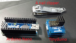
The Arduino Uno is a good board to use; it uses the same ATmega328P that the TinyDuino uses.  However, we cannot use this reliable board because at 28 grams it is too big and heavy. The Arduino Pro Mini and Mini series are smaller versions of Arduino Unos, weigh only 4 grams and are much, much smaller in size.  However, the consensus on quadcopter forums is that the Pro Mini and Mini are troublesome to work with and have a reputation of failing more frequently.  

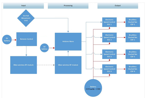
The final board we have decided on is the Arduino Nano.  The Nano is very similar to the Uno and Pro Mini, weighs in at 4 grams, and has been proven reliable in the past.  In fact, one of our team member has used the Nano in his EE444 class where it was used on a robotic rover.  The Nano runs off of 5V battery source which could be provided by the onboard Battery Eliminator Circuit (BEC) of one of the speed controller. Below is the provided specification for the Arduino Nano.  It has 14 I/O pins which is more than enough control outputs for PWM purpose.  At $10 dollars each, the Nano is a good choice.

01 

Microcontroller ATmega328
Operating Voltage (logic level) 5 V
Input Voltage (recommended) 7-12 V
Input Voltage (limits) 6-20 V
Digital I/O Pins 14 (of which 6 provide PWM output)
Analog Input Pins 8
DC Current per I/O Pin 40 mA
Flash Memory  32 KB (ATmega328) of which 2 KB used by bootloader
SRAM 2 KB (ATmega328)
EEPROM 1 KB (ATmega328)
Clock Speed 16 MHz
Dimensions 0.73″ x 1.70″

Parts list and projected cost


By Tuan Vo, Project Manager 

Quantity Name Purpose Cost per unit Vendor
1 Arduino Nano Microcontroller $17.50  (Amazon)
1 Epoxy-Resin for Carbon Fiber Build structure $32


(Ebay,polymerproducts)


2 Carbon Fiber Carbon Fiber Cloth Fabric Plain Weave 50″ 12k 300gsm Build structure $47 Ebay, elitemotoring)


1 Electric Styrofoam cutter Build Structure $39 Ebay- jossynicky0806)


1 Magic-Sculpt self-hardening epoxy modeling clay 1 lb. Build Structure $28.5 (Ebay,artplace)


2 Foam block Build Structure $30 (Michael’s Arts)
20 Connectors (Generic and assorted) Interface $30(total) JK Electronics
1 Switch Safety on/off $3 JK Electronics
2 Perforated board Connection and interfacing $7 JK Electronics


Total=$234


Schedule (from beginning of project)
6

Tasks (by team member):

Tuan Vo: Build Body, integrate subsystems, assemble body, test microcontroller, develop safety cutoff, prototype connections and general electrical assembly.

Jake Rice: Test IMU, develop control codes, test control of flight, interface communications with control.

Juan Motano: 3D modelling (omitted from schedule), develop communications, test communications, develop communication code, interface communication with control.

Resource Report

By Tuan Vo, Project Manager


The weight of the aircraft must be of proportion to the amount of thrust the propulsion components can support.  This resource reports defines resource as all components, power, and mass requirements related to the aircraft.

Study by Juan Montano on components and mass provides us with total mass when powered by 4 fans.  Note the structure mass is estimated based on a previous model hexacopter using all the same components except the Tinyduino controller and number of fans. Also at the time of writing this document, the two batteries are being shipped. 

Part/#fans Measured weight (total)
Fan (4) 460g
ECS(4) 120g
Battery* 380g
Structure** 298g
XBee 7g
Arduino Nano 8g
IMU 2g
Components (excluding the body) 977g
Total: 1275g


Power resource: 

Part Voltage(V) Current
Electric Fan 14.8 16.5A @ 100% thrust
Arduino Nano 5V NA
XBee 2.8-3.4V NA
IMU 3.3V 10mA
LiPo 4s 14.8 14.8V 1300mAh (2600mAh total)
9V battery 9V 500mAh

* The Arduino Nano, XBee, and IMU operates under 50mAh which is negligible considering the current draw of the fans is many thousand times larger.


Task Description 

  • Receive parts from customer.
  • Evaluate parts for functionality. Make lists of parts needed.
  • Determine system requirements from mission objectives obtained from the customer.
  • Establish model of the aircraft using 3D modelling.  Create major components needed such as fans, microcontroller, and power source.
  • Write a Preliminary Design Document to give to customer to obtain funding.
  • Purchase parts.  Work with programming the microcontroller and wireless communication device, XBee, while waiting for parts to arrive.
  • Build a remote control device to receive user input and transmit via XBee to the microcontroller.
  • Build the body of the aircraft.  Cut the foam for the middle section and mold carbon fiber for the top and bottom piece.  Cut out as necessary.
  • Do systems tests that can be done without mounting the fans onto the body.
  • Mount fans onto the body and carry out the rest of the system tests.
  • Final adjustments to programming and structure based on tests.
  • Final presentation to the customer.

Level 2 Requirements

By Tuan Vo and Elaine Doan

Structural Subsystem Requirements

  1. The VTOL will use four 55 mm electric ducted fans per the request of the customer. The four fans gives enough thrust to lift themselves, the required electronics for control, and a body.  The body is estimated to be 298g from the fan selection study by Juan Montana and will give control of 36.5% thrust control. Using a margin of 15% for the mass of the body, we conclude that the body of the aircraft, not including any electrical components, must weigh less than 343g.
  2. Weigh the body and ensure this does not exceed 343g.
  3. After mounting all hardware and body along with the four fans, run the fans at 63.5% thrust.  The VTOL must achieve takeoff at this point.

Wireless Communication Requirements

  1. To wirelessly control the VTOL from a minimum range of 40ft, the VTOL system will include the XBee wireless RF module (maximum range of 100m or 300 ft.). The transmitter of the XBee wireless RF module will be connected to the remote control. The receiver of the XBee wireless RF module will be connected to the Arduino.
  2. Perform communication testing of the XBees using X-CTU. Make sure the “Baud Rate” of both the transmitter and receiver match each other. (https://sites.google.com/site/xbeetutorial/xctu).
  3. Using the remote control, command the VTOL to move forward, backward, up, down and side to side. The range of communication must be at least 40ft. 

Control System Requirements

  1. To achieve flight at the elevation of 8ft, four electronic speed controls will be used to increase and decrease the speed of each fan by 20% at a reference of 63.5% lift off thrust.
  2. Write a test code using the Arduino Nano to control the speed controllers and monitor it as it run at lift off thrust. Determine if the VTOL reaches desired height by comparing with an obstacle or measurement. The VTOL must stay at desired height with a deviation of 1/2 feet. 
  3. Raise or lower the speed of each fans individually by +/- 20% thrust.  Watch and confirm expected desirable increase or decrease in fan rpm.  This increase and decrease determines the VTOL’s directional movement.
    1. To support flight around the ECS 317 room, the VTOL will use the inertial movement unit. The inertial movement unit includes an accelerometer and gyroscope that will prevent the VTOL from undesired tilting, drifting or flipping during the flight around the room.  The inertial movement forms a closed loop control system that will stabilize the VTOL throughout its flight around the ECS 317 room. 
    2. Create a test program using the Arduino that will monitor the amount of tilt and acceleration present as the IMU is moved.
      1. To achieve flight (vertical lift off), weight is a major concern; as a result, the microprocessor of the VTOL will be the Arduino Nano.  The Nano weighs only 4 grams and at the same time its I/O ports are accessible to support four fans and receive inputs from both the user and the IMU.
      2. Specs of the Arduino can be verified at the link provided below: http://arduino.cc/en/Main/arduinoBoardNano#.UylKA_ldXGA

Power System Requirements

To provide enough power for the VTOL to fly around the ECS 317 class once (85.75 ft.), the main motor battery(s) must provide a minimum 1489 mAh to sustain required flight time. This will provide the speed controls and consequently the fans with enough power to provide 70% thrust for 2 minutes. The batteries chosen are two 1300mAh LiPo batteries.  Two speed controllers and two fans will be connected to one battery. 

  1. Verify at battery study and mAh ratings link: https://www.arxterra.com/motor-battery-selection/
  2. Before testing the batteries in actual flight, hook up the batteries to their specified fans.  On full charge, have the batteries power the fans at 70% thrust and record time from full to empty, signified by when any of the fans start to reduce in rpm. Time recorded must be longer than two minutes minimum flight time. 

 System Block Diagram
4


System Interface
5


Level 1 Requirements

Level 1 Requirements – By: Tuan Vo and Elaine Doan

  1. The VTOL will be designed with a flat conical frustum base and a dome (semi-sphere) attached at the top center of the conical frustum to model after the UFO from the movie, The Day the Earth Stood Still.
    1. Compare the 3D drawing created by team to a picture of the UFO, approved by the customer.
  2. The VTOL will fly once around the ECS 317 room (The room is measured to be 30 ft. wide and 23 ft. long. Assuming an oval flight path, distance to be travelled is 86.75 ft.)
    1. Test: Erect a perimeter with the same square dimension as room ECS 317.  Fly the VTOL aircraft around the inside perimeter one time.
  3. For safety and to avoid contact with people, the VTOL aircraft will fly at minimum elevation of 8ft from the ground.
    1. Test: Use measuring tape to indicate on the wall where 8ft is. Achieve vertical takeoff and hover the machine at 8ft, indicated on the wall.  Control and move the VTOL aircraft around and make sure that the elevation remains at 8ft with deviation of 0.5 ft. or less for the duration of flight.
  4. The VTOL will be controlled wirelessly from the minimum range 40 ft. (the distance from one wall to the opposite wall of the ECS 317 room).
    1. Test: Stand at one end of the ECS 317 classroom and wirelessly control the VTOL across the room to the opposite wall.

UFO Introduction with Mission Objective and Desired Look

By Tuan Vo, Project Manager

A vertical takeoff and landing (VTOL) aircraft is one that can ascend vertically into the air and land the same way.  There are many quadcopters and hexacopters that have achieved this feat. The use of electric ducted fans (EDF) to accomplish VTOL and hover flight is rare and have not been widely established.  This project will attempt to use EDF’s to achieve VTOL and hover flight in a fashionable manner.

Mission Objective:
Build a VTOL aircraft modeled after the UFO from movie The Day the Earth Stood Still.  The VTOL will utilize some of the major components provided by the customer and be controlled wirelessly to fly safely around a classroom.

The desired look: (taken from the movie)
1


Rough 3D model:
2


Exploded View:
3

Bioprinter “Ink”

Above, Agar plate with growing cells

By Ali Etezadkhah, Project Manager

To grow and take shape, cells need a skeleton or scaffold to attach to.  They also need access to nutrients to survive.  There are many different types of cell growth media and they range from pure liquid to a solid gel.  Most people have had experience with the solid type in their Biology class.  Petrie dishes covered with a thin layer of agar are used for growing cells in biology labs.

 Agar is a combination of the linear polysaccharide agarose and heterogeneous mixture of smaller molecules called agaropectin.  Because it is a mixture of different types of molecules, the gelling point of agar is unpredictable.  Controlling the gelling point is very important for 3D printing.  As such, agar is not a good choice as the “ink” for the printer.

A pure form of agarose is available for a number of manufacturers.  It is usually used to separate DNA fragments based on their size and molecular weight.  The procedure is called electrophoresis and utilizes an electric current and a sieve created by the solid agarose gel.  Because it is a pure molecule, agarose has a very tight gelling point, a very desirable property for 3D printing.  In addition to the narrow gelling temperature range, agarose also provides a sturdy gel when solid.  We chose a formulation with very high gel strength to ensure our printed objects hold their shape.  We chose formula A0169-10G manufactured by Sigma-Aldrich.

This agarose formula melts between 86.5 and 89.5 degrees Celsius and gels between 34.5 and 37.5 degrees Celsius.  This hysteresis is a valuable property because it gives us plenty of time to load the gel into the printer after it has melted.  The published gel strength is 1200 gm/cm2, which is the amount of weight needed to depress the gel a distance of 4mm with a 10mm probe without breaking the gel.

Commercial bioprinters use two extruders, one to print pure agarose gel and one to print a watery solution of cells.  This allows the operator to create intricate tissue or organs.  Our printer only has a single extruder so we are limited to printing with a mixture of agarose and living cells.