Hexapod Forward and Backward Movement Calculation and Algorithm

By Chau To

Introduction:
Hexapod uses the tripod gait (3-leg combined showed in Figure 1) to perform forward and backward movement. In order for the Hexapod to move in a straight line, it is required all of the servos such as shoulder, femur, and tibia servo to be operated simultaneously. This blog post will give a detail calculation for the angle that each servo needs to make to compensate with one another. This blog post will also introduce the algorithm for the Hexapod forward and backward movement.

Hexapod Movement Analysis and Calculation:
The Hexapod will use 3 legs at the same time for movement as showed in Figure 1.

 figure 1

Each leg composed of a femur and a tibia and is controlled by 3 servos: shoulder servo, femur servo and tibia servo as showed in Figure 2. 

figure 2


 Forward and backward movement analysis:
When the Hexapod is moving, if the Tibia servo does not rotate, the Hexapod body will be shifted by the “x” distance (bottom picture in figure 3.) The purpose of the following calculation is to find the angle of the Tibia and Femur to compensate and to prevent the “shifted body problem.”

Let’s declare the variable like in figure 3:

figure 3


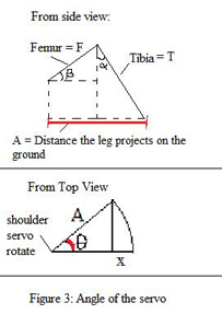
  • F is the length of the Femur (from the shaft of the Femur servo to the shaft of the Tibia servo)
  • T is the length of the Tibia (from the shaft of the Tibia servo to the ground)
  • α is the angle of the Tibia assuming that the initial position of the Tibia is perpendicular to the ground.
  • β is the angle of the Fumur assuming that the initial position of the Femur is parallel to the ground.
  • A is the project of the leg on the ground
    • θ is the angle the shoulder servo rotates
    • x is the distance that the body is shifted

 Let’s α’ be the new angle of the Tibia servo to compensate the x distance:

 The angle that the Tibia servo has to adjust:

 In order to balance the Hexapod, the Femur servo also has to rotate to a new angle

Let’s y is the length the Femur need to compensate like in Figure 4

 figure 4

Let β’ be the new angle of the Femur servo to compensate the x distance:

 The angle that the Femur servo has to adjust:

Example: Hexapod matching the speed of the Rover 0.2m/s
In order to match the speed of the Rover, each Hexapod step needs to be 4 inches assuming that the Hexapod takes 2 steps in 1 sec, and the speed of the Rover is 8 inches/s

Let the length of the Femur: F = 3 inches, length of the Tibia: T = 6 inches, and α = β = 300

  • A = 6sin(30)+3cos(30) = 5.5980 inches

To reach 4 inches, Let θ = 450  à Hexapod step will be: Asin(45) = 3.958 inches.

So, with this setting, the Hexapod should be able to match the speed of the ROVER!!!

Let calculate the angle of the Tibia and Femur for the forward movement:

  • x = A – A cos(θ) = 5.5980-5.5980*cos(45) = 1.159 in
  • α’ = 43.88660
  • ∆α = 43.8866 – 30 = 13.88660 (from initially 300 to 43.8860)
  • y = 0.8718 in
  • β’ = 120
  • ∆β = -180 (from initially 300 down to 120)

In summary, in order for the Hexapod to move in straight line with a step of 4 inches with the settings in the example, the shoulder servo needs to rotate 450; the tibia servo need to rotate an extra 140 and the femur servo also needs to rotate an extra 180.

Movement Algorithm:
Screenshot (33)

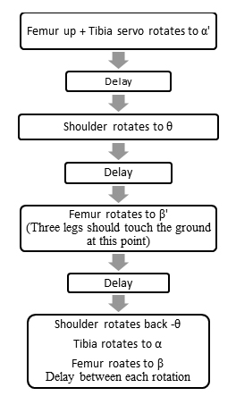
Delay is very important because it requires certain time for each servo to rotate. Therefore, each delay makes sure that the previous stage is completed. Maximizing the delay also increased the performance of the Hexapod. 

At the final stage when the shoulder servo rotates back to –θ, i.e it means that the servo rotate to the initial angle before the robot move. The delay between each rotation is very important and needs to be precise because each angle of the leg servos might be different from each other.

Motor Trade-off Study

By Anthony Vo

In order to decide which motor will meet our level 1 and subsystem requirements, it is important to conduct a trade-off study of several motors.  The goal of the trade-off study is to compare and contrast the RPM, current draw, torque, and cost of each motor.  From the trade-off study, we will be able to determine which motor will best fit out design specifications.


Type of Motor

plastic gearmotor

GM8

GM9

GM10

GM17

Cost

$5.75

$5.75

$5.75

$9.26

$5.75

           
Voltage (vdc)

6

5

5

5

6

Current (mA) free-run

70

57.6

73.2

24.6

29

Power=IV (mW) electrical

420

288

366

123

174

RPM (speed)

85

70

66

370

32.4

Torque (oz-in)

75

43

43

3.6

69

Torque (kg-cm)  

3.096

3.096

0.26

4.97

Torque (N-m)

0.529

0.303

0.303

0.025

0.487

Reduction

120:1

143:1

143:1

81:1

228:1

Weight (grams)

32

32


5

35

Weight (oz)  

1.13


0.176

1.23

Above is a chart of 5 different motors with a hyper link to each one.  The description and specification for each motor is arranged into a chart for easy comparison.  From the data above, we have narrowed down our motor to 2 choices: the GM8 and the plastic gearmotor.

GM8:
The pros for choosing the GM8 over the plastic gear motor include lower current draw at free-run and lower power consumption.  The lower power consumption allows us to meet our power requirement defined in the subsystem requirements.  However, this motor will not provide the RPM required to achieve our speed requirement at the rated 5 volts.

Plastic Gear Motor:
The pros for choosing the plastic gear motor over the GM8 include higher RPM and higher torque rating.  The higher RPM ensures that our level 1 speed requirement is met.  This motor also provides more torque which will allow the rover to move over more difficult terrain without stalling.

Conclusion:
After comparing the two motors, we are leaning towards the plastic gear motor.  Although the motor is less power efficient, it will still meet the subsystem power requirements.  The plastic gear motor will provide the RPM and torque we need to drive the rover at our speed requirement.

Updated Upgrade Parts List

By Gregorio Rios – 3D Modeling

The tables below show the additional parts needed for the upgrades. As we advance in building, we may need additional parts. 

Bearings
bearings

Motors & couplings
motors

Electronics
electronics

Rods
Threaded rods
Only 2 M5 threaded rods are needed:  (WE HAVE)

  • 2x Threaded rod M5x295 mm

Smooth rods
6 Smooth rods are needed of the following sizes:

  • 2x Ø8×375 mm for X-Axis (WE HAVE, BUT ARE 500MM LONG. WE CAN LEAVE THEM OR CUT THEM)
  • 2x Ø8×341 mm for Y-Axis (WE HAVE)
  • 2x Ø8×320 mm for Z-Axis (WE HAVE)

Get Up and Running With the Arxterra Control Panel & Android Applications

By Tommy Sanchez

If you are interested in controlling your robot with the Arxterra control panel, you have come to the right place. For your robot to be controlled through the control panel, you will need to have an Android phone for communication with your Arduino. This guide will show you how to create an account with Arxterra, get access to the alpha testing for the Arxterra applications, connect on the applications, and log in to the control panel. The provided link below will take you to an easy to follow step-by-step PowerPoint tutorial outlining these topics.

PowerPoint Tutorial:
http://www.csulb.edu/~hill/ee400d/Lectures/12_Arxterra%20Login.pptx

Obtain and repair STL files

By Vinh-Khoa Ton, Control and Image Processing

Purpose of this process:
After obtaining the STL files for all ROFI parts, we needed a way to create a “clean” version of the modulated STL files. The purpose of this process was to eliminate all holes, gaps, and unclosed surfaces on the parts to ensure the quality of the 3D printed products.

Obtain the STL files:
1. Download the ZIP file that contains all the required 3D printed parts for ROFI at:
https://docs.google.com/file/d/0By_h1KTMNaWNNFlCLUJMY0dUbUE/edit
2. Extract all files into a folder.
3. Next, we will analyze and repair these files.

What software to use:
There is plenty of software available on the internet. We used Netfabb because it is free and easy to use, with or without installation of the program.
I. Without installation of Netfabb: this is a quick solution to repair a few parts without the need to download and install the application on computer.
1. Go to http://cloud.netfabb.com/

picture1

2. Click “Choose File” to select the STL that you want to fix.
3. Enter your email address (the repaired STL file will be sent to this email).
4. Choose the appropriate measurement unit that was used when the STL part was created (millimeters by default).
5. Click “I accept the terms and conditions mentioned below” and click “Upload to Cloud”. The page will open an upload progress dialog box shown below.

picture2

6. If successful, a confirmation will appear.

picture3

7. Open the email address entered above.
8. Click the download link provided in the email.

picture4

9. Click “Download” next to “Repaired file.”

picture5

10. Save the repaired file to computer.

II. With installation of Netfabb: a powerful software that allows users to easily repair multiple STL files.
1. Download the Netfabb Basic. Go to: http://www.netfabb.com/downloadcenter.php?basic=1
2. Select your computer operating system and click the download button.

picture6

3. Click the generated link to download Netfabb Basic.

picture7

4. Run the downloaded setup file “netfabb-basic_5.1.0_win32.exe” and follow the instructions
to install Netfabb Basic. (Note: Admin privilege may be required)
5. Open Netfabb Basic. Click Project -> Add part -> Go to the STL folder, select all of the parts and click “Open”. The software will load all of the selected parts, which can be viewed in the right-hand panel shown below:

picture8


Note: You can click the eye icon next to the part name to enable/disable its visibility.

6. Choose the part that needs to be repaired. From the menu bar, choose Extra -> Repair Part. A new item will appear below the original part.

picture9


7. Right click on the new generated item (called “Part Repair”) and click “Apply part repair”.

picture10

Choose “Keep old part” in the next confirmation window.
8. A new item will be generated. Right click on this part and choose Export part -> choose “As STL”.
9. Save the repaired file to your computer.
10. Repeat the above steps for the remaining parts.

Conclusion:
Netfabb is an easy to use and free software for repairing 3D printed parts while providing helpful tools for other 3D modeling functions such as an automatic repair tool, a slicing tool, and an analysis tool. We chose to use Netfabb because it provided enough applications for the Biped project to meet our requirements.

Ultrasonic Sensor Examination

By Vinh-Khoa Ton, Control and Image Processing

The purpose of this ultrasonic sensor examination was to determine the range and angle of the sensor detection. The ultrasonic sensor will be used as the eyes of ROFI and ROFIA for the purpose of avoiding obstacles. The Seeed Studio Ultrasonic Ranger v1.0 was the device chosen for this examination.

sensor

Examination Setup:
An Arduino ATMega328 was used to test the sensor. The connections between the ultrasonic sensor and Arduino are shown below.

schematic

The sensor was set at approximately 30 cm, the height of the robot. The sensor was placed on a hard and flat surface to ensure stability during the test. A black binder was used as an obstacle for easy angle adjustment (1 side is fixed and 1 side is adjusted).


test setup

The code used for the tests can be found in the dropbox link at the end of this post. The serial monitor, shown below, was used to record the distances at which the sensor detected an obstacle. The LED was programmed to light up if an object was within 30 cm of the sensor.

serial monitor

Detection Angle Testing:
A question that the test was designed to answer was: would ROFI and ROFIA be able to detect an object at their feet? To answer this question, the angle of the adjustable side of the binder with respect with the table was varied from being parallel with the table to being perpendicular with the table.

demonstration1

The highest distance value that the sensor detected for an angled surface was approximately 42 cm and any angle closer to being parallel with the ground resulted in the sensor being unable to detect the binder side.

demonstration2

The highest angle that the sensor could detect was approximately 36 degrees.

theta calculation

Detection Distance and Error Testing:
The sensor was tested with an upright object, as shown in the picture below, placed at different distances. The error between the sensor’s calculated distance and the actual distance was approximately

1 cm.

demonstration3
measured data

Conclusion:
The ultrasonic sensor is able to detect objects that are equal to and less than 36 degrees vertically away
from directly in front of it, given that the object is about 27.7 cm as shown in the angle testing section.
The ultrasonic sensor has about an error of 1 cm when detecting objects directly in front of it. The angle
detection brings up an interesting scenario. The ultrasonic sensor would have issues detecting objects
below it following any turning movements. The ultrasonic sensor also has problems detecting flat and
upright objects parallel to its line of sight. For the purpose of the biped project, however, we will be
avoiding these complications and will use it to simply avoid upright objects directly in front of it.

References:
Sensor specifications, background information, and Arduino code can be found here:
http://www.seeedstudio.com/wiki/Ultra_Sonic_range_measurement_module#Introduction

The Arduino code used to test the ultrasonic sensor can be found here:
https://dl.dropboxusercontent.com/u/20231161/Ultrasonic_Sensor_Testing.ino

Determining the Number of Fans

By Juan Montano

Hello, this study will try to determine the number of fans that would be required for the UFO. The number of fans used in the UFO must meet the criteria of achieving lift off at 50% +/- ∆.

First, we determined the weight of each component currently provided to us by the customer:

Fan, ECS, Battery, Structure (Old), XBee, Tinyduino, Gyro

Component Weight
Fan 115g +/- 5
ECS 30g +/- 5
Battery 380g +/- 5
Structure

(top, mid,bottom)

400g +/-5
Xbee 7g +/-5
Tinyduino 8g +/-5
Gyro 2g +/- 1


Now, we try to determine how the mass of the structure will change as we decrease the number of fans. First, we will assume a linear regression of the diameter size of the UFO as we decrease the number of fans. We will then assume that the correlation between percentage of volume and mass is in a 1:1 ratio.

 From a different study, we determined the difference in diameter between 4 & 6 fans was between .7-1.5 inches. Using the max difference, we get ∆d=0.75”. Assume the UFO is a cylindrical shape, we will use the equation of a cylinder to determine the total volume of the UFO. We note that the old structure had d=11” and h=3”.


Fans Volume of UFO % Ratio to 6 fans Estimated UFO Weight
3   180.3/284.96*100=63% 253g
4   212.5/284.96*100=75% 298g
5   247.4/284.96*100= 87% 347g
6   284.96/284.96*100= 100% 400g


Now we determine the mass (g), and thrust for x number of fans.

Part/#fans 3 4 5 6
Fan 345g 460g 575g 690g
ECS 90g 120g 150g 180g
Battery* 380g 380g 380g 380g
Structure** 253g 298g 347g 400g
Xbee 7g 7g 7g 7g
Tinyduino 8g 8g 8g 8g
Gyro 2g 2g 2g 2g
Components 832g 977g 1122g 1267g
Total: 1085g 1275g 1469g 1667g

* We will assume a single battery as the power supply for the UFO, given to us from the customer. We may modify this, based on the battery trade-off study.

** Determined above using the old structure

Using the average thrust provided from last semester’s post burn studies, we have 502g of thrust provided by each fan.

Fans/Thrust Total Provided Structure+Components=UFO Lift UFO Control % Control
3 1506g 253+832=1085 421 28.0% +/-5
4 2008g 298+977=1275 733 36.5% +/-5
5 2510g 347+1122=1469 1041 41.5% +/-5
6 3012g 400+1267=1667 1345 44.7% +/-5


For the case of Multiple Batteries:

Here, we will assume that the mass of the battery will change with the amount of fans present. We will use the battery provided by the customer and determine the mass to be 380*x/6, where x is the current number of fans. Therefore, we will have:

Fans/Thrust Total Provided For Components For Structure UFO Lift UFO Control % Control
3 1506g 642 253 895 611 40.6% +/-5
4 2008g 850 298 1148 852 42.4% +/-5
5 2510g 1059 347 1406 1104 44.0% +/-5
6 3012g 1267 400 1667 1345 44.7% +/-5


In conclusion, we can see that 6 fans would give us approximately 50% thrust control. However, we would like to point out that there can be modifications made to the battery and/or the structure to provide ourselves with 50% thrust control using a smaller number of fans. Below, we will see how much weight the structure would have to be to provide that requirement.

Appendix A:

Here, we are going backwards to determine the maximum amount of weight our UFO (structure and/or battery combination) should be to provide a 50%+/- ∆ thrust control per number of fans. Using similar assumptions as above, we will note our fixed values.

Number of fans Fixed Thrust 50% Thrust Fixed Weight Remaining weight for battery/structure
3 1506 753 452 301
4 2008 1004 597 407
5 2510 1255 742 513
6 3012 1506 887 619

 This table above shows the fixed amount of total thrust we have and the set in weight determined by the components that are required in the UFO (Fan, ECS, Gyro, XBee, Tinyduino) and whose weight we can’t change. The remaining weight column shows how much weight the battery and structure should be to be able to maintain a 50% thrust control.

Since we can allow some leeway in the amount of thrust we should provide for control, we also show a 45% thrust control table below:

Number of fans Fixed Thrust 55% Thrust Fixed Weight Remaining weight for battery/structure
3 1506 828 452 376
4 2008 1104 597 507
5 2510 1380.5 742 638.5
6 3012 1656.6 887 769.6


Motor Battery Selection

By Jake Rice

UFO Abducted must be able to fly around a classroom using ducted fans driven by brushless DC motors. To achieve untethered flight, a battery must be used to power the motors. In selecting a battery for the UFO, the three main considerations are weight, maximum discharge current, and energy capacity. A lithium-polymer battery will be chosen due to the low weight and high discharge current of lithium-polymer batteries relative to other common types. Because the speed controllers for the motors are rated for 14.8V, the choices are limited to lithium-polymer batteries with 4 3.7V cells in series.

The main factor limiting battery choice is the maximum current draw of the motors. To maintain safe operation, the battery must be rated to supply more than the maximum current potentially drawn by the motors. Each motor has a maximum current draw of 27A, and the 4 motors have a combined maximum current draw of 108A.

In addition, the energy capacity of the battery must be large enough to ensure that the UFO completes its flight. Based on previous research, the UFO will be able to maintain level flight at under 70% of the maximum motor throttle, and at 70% throttle the motors draw 44.68A. To meet the 2 minute minimum flight time requirement, the capacity of the battery must be higher than 1489mAh.

The following chart compares several acceptable batteries. The battery purchased last semester is at the bottom of the chart.


Name

Cost

Weight (g)

Capacity (mAh)

Maximum Discharge Rate (C)

Maximum Current Draw (A)

Maximum Flight Time (min @ 70%)

Capacity/Weight Ratio (mAh/g)

Turnigy nano-tech A-SPEC G2

$49.77

296

2600

65

169

3.49

8.78

Turnigy nano-tech

$34.47

268

2250

65

146.25

3.02

8.40

ZIPPY Flightmax

$31.27

368

3000

40

120

4.03

8.15

ZIPPY Compact

$35.57

350

3300

35

115.5

4.43

9.43

Sky Lipo

$64.72

349

3000

40

120

4.03

8.60

ZIPPY Flightmax

$25.78

329

2650

45

119.25

3.56

8.05

Thunder Power G8 Performance Pro

$94.99

284

2700

45

121.5

3.63

9.51

MaxAmps LiPo

$109.99

327

3250

150

487.5

4.36

9.94


Of the batteries compared, the MaxAmps LiPo has the best capacity/weight ratio, the second-highest capacity and a far higher maximum current draw than any of the others. Using the Thunder Power or one of the Turnigy batteries would reduce the weight of the UFO. However, due to the higher capacity and the cost advantage due to the fact that we already have it, we should use the MaxAmps battery to power the UFO’s motors.

Mirror Study

By Maxwell Nguyen

In order to eliminate the need for larger servos, the rover team will be implementing mirrors to provide vision for the rover.  As compared to lifting a phone, the torque and power require to lift a mirror is substantially less.

Objective:
The objective of this study is to examine whether a mirror used for vision control will provide a clear and undistorted image.

 A study must be conducted in order to verify if mirrors can be used for the pan and tilt vision.  We will use a basic, homemade apparatus to test the camera vision through the mirror.  The apparatus can be seen below and consists of a mirror taped to a small booklet to provide stability and a tilt function.

2 

Mirror apparatus

Equipment and materials:

   -Phone with camera
   -Mirror
   -Tape
   -Small booklet

Procedure:
The setup will have the phone placed on a flat surface with the camera facing up towards the ceiling.  The phone will remain stationary throughout the entire test.  The mirror apparatus will be placed directly over the camera.  Using the flap of  the booklet, a tilt function can be simulated.  By turning the booklet/mirror left and right, we can simulate vision control to the left and to the right. 

 3

Test setup

 4

 Test setup(different angle)

Results:

The following short clip provides results to the mirror study.

Conclusion:
Mirrors do in fact provide a clear image for the camera.  Tilting and panning of the mirrors shows no distortion.  From this study, the team will move into designs to implement the mirror on the rover.

Sanding

By Gregorio Rios – 3D Modeling

3D printed objects, whether they are ABS or PLA plastic will require a method to smooth out the surface.  There will always be visible lines on the surface of the printing objects. These lines on the surface are from the layers of plastic being printed one on top of another. There are different methods for smoothing the surface, but at this time sanding will be our choice.

Before sanding, check for imperfections since printed object will always have small parts that stick out and will have to be removed. Knifes, pliers, scissors and abrasive files will come in handy for the imperfections before sanding. Remove any plastic strings or imperfections that stick out with a small sharp or little scissors.

 files

If there are any bulges on the print, use files to remove these imperfections.  Using a Dremel multi tool could also be very useful for grinding, cleaning to remove imperfections and even sanding. Now that the imperfections are gone, now it’s time to get to sanding.

 drem

As a precaution use a mask or respirator when sanding. Start by sanding the surface of the 3D printed part with a 100 or 150-grit sand papers (of Dremel wheels) then 220, 320 fine, 500 super fine, and then use a micron-grade grits to erase sanding marks. When sanding the surfaces, do so in a circular motion until it is smooth and flat to the touch. Pay attention to the act of sanding and do not rush just finish sanding the surface. Do not go too fine too fast or you will round over the plastic ridges without actually flattening them.

 sand

Use a heat gun after sanding the surface. Gently warm the surface until it melts slightly, which will erase many of the smaller scratches and restore the original printed color.

 heat

If you would like to paint it use 3 to 4 coats primer before color paint. Make sure that the primer is completely dry before masking off any undesired parts that you do not want to color. Be sure that the masked edges are firmly taped on and sharp. Start with a light color coat as well as a light sanding (600 grit) between each coat. Spray 3 to 4 more coats of color spray paint (or airbrush) on desired areas. 

 lizard

REFERENCES:

http://makezine.com/projects/make-34/skill-builder-finishing-and-post-processing-your-3d-printed-objects/

http://edutechwiki.unige.ch/en/Post_processing_of_3D_polymer_prints