Advanced 3D Printer Possible Improvements

By Mustafa Alkhulaitit – Project Manager

3.rapman_closeup

After studying the company’s objectives, our group has decided on some of the possible improvements that can be applied on the 3D printer to meet those objectives. This blog is only to list the different possibilities without analyzing each and every one of them. Future blogs will include further analysis and research studies.

  • Frame upgrades – the frame of Sasha is to up upgraded to a stainless steel frame that would provide the printer with more durability.
  • Auto bed leveling
  • Dual extruder heads
  • All metal hot end
  • Auto calibration
  • Box enclosure
  • Bridging fan
  • Surface toning
  • LCD panel/SD reader
  • Heat bed

The first five upgrades will be our group’s top priority, since they meet most of the desired objectives.

Level 1 Objectives

By Mustafa Alkhulaitit – Project Manager

There are multiple objectives for the advanced 3D printer project. Those objectives will eventually lead to the requirements of the group, where requirements will determine the type of upgrades and improvements that will apply to the printer.

The objectives can be summarized as follow:

  • Reliability – how reliable is the printer and the printed object
  • Elimination of shape restrictions – there are many shapes that cannot be printed by regular 3D printer
  • Repeatability – loss of precision after the first print
  • Resolution – how clear is the printed object
  • Reducing print time – time to setup and time to print

For each of our objectives, we will have a research study that will be posted in future blogs.

Introduction to 3D Printing

By Mustafa Alkhulaitit- Project Manager
Gregorio Rios: 3D Modeling Division
Jessica Salazar: Manufacturing Division

The world of 3D printers is rapidly growing and expanding. New models are invented every day and new technologies are used in 3D printers. Lack of knowledge in this field will lead to confusion about the many different devices, models, and updates related to 3D printers. Therefore, the first step in our plan was to get familiar with 3D printers and technologies involved with them in order to determine our requirements and objectives.

Researching 3D printers will lead to a better understanding of 3D printers and, as a result, will give us a better opportunity to upgrade and improve Sasha, the 3D printer.  We will be able to easily figure out the best possible improvements that meet the company’s expectations. 

Servo Examination

By Kevin Huynh, Project Manager / Computer Systems and Software

The purpose of this servo examination was to discern the reason for the servos malfunctioning. During the servo testing, it was discovered that three Power HD 1501MG servos were broken and the broken servos were closer to the feet of the robot, suggesting that the load was wearing out the servo by shear stress. We took apart the servos to figure out why the servos were actually breaking. Four servos were taken apart to examine the servo gears and shaft, three of the servos were the nonresponsive Power HD 1501MG servos mentioned in the servo functionality testing and one was a functional Power HD 1501MG servo as a base to compare the broken servos to. There seemed to be nothing physically wrong with the servos.

ServoGears

Next, we examined the circuit board on the other side of the servo. Two of the three broken servos had burned circuit boards, the third servo appeared to have no damage at all.

BurnedServo

Servo Examination Conclusion:
Since there seemed to be nothing wrong with the gears or shafts of the servo, it is unlikely that the servos were directly damaged by carrying the weight of ROFI. Since the circuit boards were burned, it is likely that the servos drew too much current and overheated. This is likely the result of the servos stalling, but continuing to draw a large amount of current in an attempt to reach the position specified by the programming. The constant draw of current eventually overheated the servo and burned the circuit board. We will be looking into ways to prevent the servos from drawing too much current from the LiPo batteries even if the servos stall, starting with a foldback current limiter.

Spiderbot: Chop Suey Returns

By Matthew Clegg, Computer & Control Systems

Chop Suey has returned! David Gonsalez, a member of the Hexapod team from the previous semester, has loaned us the hexapod prototype he built. Having access to an already built prototype will save time and money because we will not have to devote resources to make one. It will also allow me to visualize how the servos will be working to move the legs and body, depending on which type of walk, or gait, the Spiderbot will use.

We scouted the area where Spiderbot will be required to move through and took measurements of obstacles. After previewing the terrain, it seems that Spiderbot may have to switch between two different types of gaits in order to overcome obstacles and move with good speed. The two gaits in consideration are the tripod gait, which will allow for a greater speed on level surfaces, and the wave gait, which is slower but will allow for more stability over uneven terrain.

Further explanation of these gaits can be found in the blog of the previous semester’s Hexapod project.

Sprinkler_Top

The length of some of these obstacles will also affect the distance that the legs of Spiderbot will have to sweep.  This will be determined in part by the length of the legs. The photo above indicates that the maximum width of the obstacles from a top view (both sprinkler heads and branches) measured to 2.5 inches, which is the leg sweep that will be required of Spiderbot.

In accordance with the previous semester’s design choices, we have also decided to use the Arduino Mega ADK, as well as the Adafruit 16-Channel 12-bit PWM/Servo Driver in Spiderbot’s design. The Mega ADK will allow for fewer complications when interfacing with an Android smartphone because of the dedicated usb port placed on the board. The Mega ADK will not be able to support the number of servos we will be using (a total of 20 servos!), which is why we will be using servo drivers. The use of the drivers will also free up processing power from the Arduino ADK. These components are shown below:


ArduinoADKFront450px

Image from: http://arduino.cc/en/uploads/Main/ArduinoADKFront450px.jpg


adafruit-16-channel-i2c-servo-controller-1_1

Image from: http://www.robotshop.com/media/catalog/product/cache/1/image/800×800/
9df78eab33525d08d6e5fb8d27136e95/a/d/adafruit-16-channel-i2c-servo-controller-1_1.jpg

The next thing in store for Spiderbot: trade-off studies of servo motors for leg operation of Spiderbot and familiarization with everything Chop Suey has to offer to better our design.

Servo Functionality Test

By Elaine Doan, Systems and Test Engineering

Servo Functionality Testing
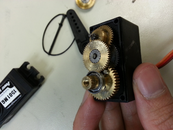
The objectives of this test were to verify that ROFI’s servos were working correctly. There are two servos that the CSULB Biped group is concerned with: the Towerpro MG996R servo and the Power HD 1501MG servo. These two servos were used in both ROFI and ROFIA, with ROFI having a combination of both servos and ROFIA using exclusively Power HD 1501MG servos.

Servo Test Materials
1. Arduino MEGA 2560
2. Towerpro MG996R and Power HD 1501MG on ROFI
3. UBEC-5A-HV DC-DC regulator

Servo Wiring Procedure
1. Connect the red wire to the positive terminal of the UBEC and the brown wire to the negative terminal of the UBEC DC-DC regulator. Do not connect either the red wire or the brown wire of the servo to the Arduino, there is a possibility that the servo will draw a lot of current and destroy the Arduino.
2. Connect the orange wire to an Arduino output pin. The orange wire is the control signal terminal of the servo and will allow you to control the servo with the Arduino.


Testing Code
The following code will command a servo on Arduino PIN 8 to rotate 60° clockwise within two seconds, then rotate 60° counterclockwise within two seconds. This process is repeated until the Arduino is turned off. The servo is assumed to have been centered before the test, but can be centered by using myservo.write(90).

#include <SPI.h>
#include <Servo.h>            // Include servo library

Servo myservo;               // create servo object to control a servo

void setup()
{
 myservo.attach(32);           // attaches servo on pin 8 to servo object
}

void loop()
{
 myservo.write(1);             // Move servo to 1 degree angle
 delay(2000);                  // Delay 2 seconds
 myservo.write(120);           // Move servo to 120 degree angle
 delay(2000);                  // Delay 2 seconds
}

Servo Test Conclusions:
Three of the twelve servos on ROFI were found to be completely non-responsive. All of the nonresponsive  servos were Power HD 1501MG servos and tended to be close to the feet of the robot, suggesting that the load was responsible for breaking the servos. Following this is a diagram and table detailing the results of the servo test.


ROFI

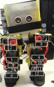
Servo#           Servo Type                       Result
    1                      Towerpro MG996RC        Functional, rotates 90°
    2                      Power HD 1501MG           Functional, rotates 120°
    3                      Towerpro MG996R           Functional, rotates 90°
    4                      Power HD 1501MG           Nonresponsive
    5                      Towerpro MG996R           Functional, rotates 90°
    6                      Towerpro MG996R           Functional, rotates 90°
    7                      Towerpro MG996R           Functional, rotates 90°
    8                      Towerpro MG996R           Functional, rotates 90°
    9                      Towerpro MG996R           Functional, rotates 90°
    10                    Power HD 1501MG           Nonresponsive
    11                    Power HD 1501MG           Nonresponsive
    12                    Towerpro MG996R           Functional, rotates 90°

Demonstration Video
http://youtu.be/hO09e36LdrU

Datasheets available at:
Power HD 1501 MG: http://www.pololu.com/file/0J729/HD-1501MG.pdf
TowerPro MG996R: http://www.towerpro.com.tw/driver/drivers/Towerpro%20servo%20spec.pdf

Spiderbot – Life & Times (Vol. 2)

Spiderbot_Logo_smaller

By Kristine Abatay, Project Manager

main()
{
printf(“hello, world!”);
}

It is a new semester at Robot Company and with it, a new Spiderbot!

 Our mission: construct a six-legged robot that will match the speed of the Robot Company’s rover project, operate safely, and have the capability of maneuvering a route in a natural setting.

 This robot will have a spider-like appearance and walk, but with six legs instead of eight, all the while being controlled wirelessly using an application for Arxterra, designed for Android smart phones. Spiderbot will achieve a speed of 0.2003 m/s on a flat surface – the calculated speed using specifications from components of the rover project last semester.

Click here to see the calculation used to determine the speed requirement  

The natural setting that Spiderbot will be able to maneuver is located on the East Wing of the CSULB campus as shown by the following map:

Map

 Our group surveyed the area and created a route for Spiderbot to complete as indicated in the picture above and the total length measured to roughly 42 m. This is the same path that will be used to test both the Rover and the Hexapod projects. A quick run through of the route can be found in the following link:

The pictures below are some of the obstacles encountered while surveying the Spiderbot route. A sprinkler head with a height of roughly 4 inches and a branch with a width of 2.5 inches were the most notable obstacles. These measurements will dictate the overall body design of our Spiderbot. In addition to these design requirements, our Spiderbot will function properly while following the health and safety policy of the engineering department of CSULB (found here: http://www.csulb.edu/colleges/coe/views/safety_and_environment/safety_policy.shtml).

SONY DSC

Our date of completion is set for May 12, 2014 so stay tuned for future updates as we progress in our construction of Spiderbot!

ArxRobot Alpha 0.1.25 Posted

ArxRobot version Alpha 0.1.25 has been uploaded to Google Play at https://play.google.com/apps/testing/air.com.arxterra.arxrobot

From now on, the version name should be visible at the lower right corner of the ArxRobot window.  If your Android device does not offer to update your app within a reasonable time, please go to the URL above.

The following are some highlights of what has changed since the previous update:

  • Added a Connection Configuration View with server presets in place of hard-coded server address (normally you will still want to accept the default, but now we have more flexibility for development, testing and demonstrations).
  • Implemented storing your Robot Capabilities settings in App Storage on the Android device.  User eventually will be allowed to choose between storing capabilities there or in Arduino EEPROM.  Currently the EEPROM option is disabled.
  • User can now post Robot avatar images online for the Control Panel to display in the map pop-up and in the position array.  In the Login View on ArxRobot, the user enters the absolute http path to the web directory where these are stored.  5 PNG files are expected (with transparency, 400×400 pixels or smaller).  They must use the following naming convention:  beauty.png (for the map pop-up), front.png, iso.png, right.png and top.png.  Two relative path options, “pathfinder” and “rosco”, are also available if you want to let the Control Panel use its stock images of one of those prototypes.
  • Added contextual help to the Login View, with tooltips that appear if you press and hold wherever you see a highlighted question mark [?].
  • We upgraded our SmartFoxServer installation, which has a new IP address.  To get the latest version of the Control Panel and Server, please be sure to start your Control Panel session from the Arxterra.com website and avoid using old bookmarks you might have made during previous sessions.

We expect to be releasing another ArxRobot and Control Panel update in the next couple days, which will add the Custom Controls API we promised to those with walking bots that need to be able to change posture and gait.

Riverside Robot Expo 2013

Riverside Robot expo was awesome this year. Ran into some familiar faces and reconnected with some other maker groups. Vocademy is opening a Riverside Makerspace space in the area and we can’t wait to see what they start to offer. Thank you the the Riverside Robotics Society for putting this on.

20131102_155536 20131102_114401 20131102_110419

Northern California Maker Faire Tour!

We had a blast at all the Faires. It was Santa Rosa’s first shot at it and the people where great! East Bay Maker Faire was as expected from the people who bring you the larger Bay Area Maker Faire. We couldn’t leave our booths for either event! All in all a good trip. We met a lot of interesting makers and enthusiasts! See you next year!

20131019_085830 20131019_101422 20131020_092105