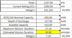
This post contains the general template for the power budget. Utilizing this for each project is highly recommended as it details how much current is flowing through each system, so that adjustments can be made in other areas of the project.
Goliath Fall 2017
By: Nornubari Kanabolo (Mission, Systems, and Test Division Manager)
Power Budget
Power Budget General Template
Research
Nornubari Kanabolo (Mission, Systems, and Test Division Manager)
Understanding what was needed to complete the power budget for the 3DoT board required finding out what components draw current from the battery in use. The battery to be used is the RCR123A 650mAh, 3.6V Li-Po. Components of the 3DoT can be found in the schematic for the 5.03 version of the 3DoT board. For the schematic, click the following link: 3DoT 5.03 Schematic
Breaking the components down into where they draw current by categories seemed to be the most efficient way to approach finding the power budget. It was broken down into the LDO at 3.3V and the 5V output of the boost converter. It starts with the LDO, which includes the internal circuitry of the actual 3DoT board, sensor shield, and header shield. At the 5V output is the motors. The final category is the battery sensor and servos.
Calculations for the LDO were found using equations from: LDO- Low Dropout Regulator
Calculations for the boost converter were found from: TPS61200 Boost Converter
The complete power budget spreadsheet can be seen by clicking the following link: Power Budget.
How to Use
Nornubari Kanabolo (Mission, Systems, and Test Division Manager)
Seeing as this is a project specific template for the Goliath, there obviously needs to be components and values inserted for other projects. This section is to show the other projects where to insert their own values.
The blue area in the image above is where each project will insert their sensor items and their respective current draws. It is best for the values to be measured, but a datasheet would do just fine.
The red area should be any components that is not a sensor, motor, or servo.
The green area is where the servo values will go if a project does indeed use servos.
Once all these values are inputted and the calculations by the document is done, all the information about the power consumption for a specific project will be shown. This includes the total current draw and the maximum mission duration as can be seen below.


