No-Load ISR
By: Jordan Smallwood (Pathfinder Project Manager and Electronics & Control)
Approved By: Miguel Garcia (Quality Assurance)
Table of Contents
Introduction:
The idea is that if any of our motors are under a no-load condition we want to cease power to that motor, since it makes no sense to waste power on a freely spinning motor. In order to do this we will need to understand the conditions present when our motor is experiencing no-load. This is determined in the motor-mock up study found HERE. Since current is proportional to the load that the motor is experiencing we can check the current to each motor and compare with the conditions. This will be implemented with an internal timer interrupt.
The robot will not be travelling that fast and we can set a timer interrupt with a period of 100 ms that will check the motor conditions every 0.1 seconds. Also, one of the things to keep in mind is that we need to know when the motor is ready to have power reapplied to it. So whenever we enter this interrupt routine we will check any of the motors that are off to see if a load is present.
Software:
Intro to Timers:
In order to set up the timer based interrupt we need to briefly overview internal interrupts. Internal interrupts make use of the Arduino timers, for the Mega we have 6 timers. Any time you decide to make use of a timer it is paramount that you make sure it is not already in use or that pins associated with that timer are not being used (e.g PWM pins). There are two different size timers on board the Arduino, 8-bit and 16-bit, depending on the resolution needed. Also, all of these timers depend on the internal clock of the Arduino which may be 8 or 16 MHz depending on what board you are using. In my experience always leave timer0 alone, it is used heavily within functions and is best left untouched.
Timer Registers:
Figure 1: Timer/Counter 5 Control Register A
Figure 2: Timer/Counter Control Register B
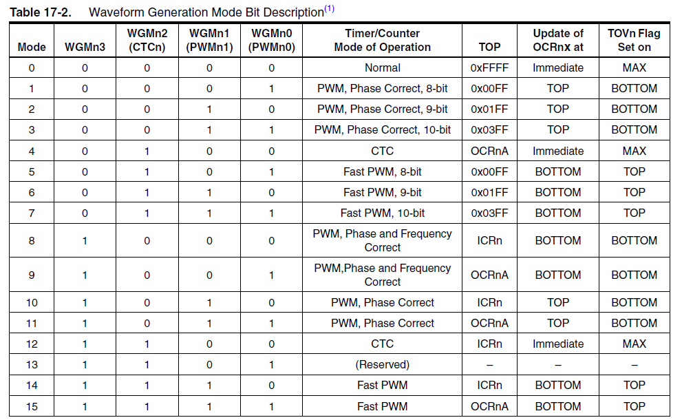
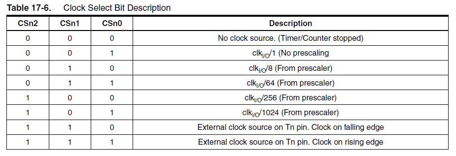
These 2 registers contain all the bits that describe the function of your timer. The only bits that we will be concerned with are the WGMnX and CSnX bits. The others become more complicated and there is not need for them with what we are trying to do. For our purposes we will have the timer in CTC mode (Clear Timer on Compare Match) and we will load a certain prescaler depending on the desired frequency. Note that this can be done in normal mode in which we preload the timer with a value and set up a timer overflow interrupt. However, we chose to do CTC mode. The tables below describe the various modes and prescalers:

Table 1: Waveform Generation Mode Bit Description/Truth Table
Table 2: Clock Select Bit Description/Truth Table
If we are using the CTC mode then we can realize that we need the following line of code:
Figure 3: Setting Timer 5 to CTC mode
The following scheme can be used to determine the value to compare the timer with and the required prescaler.
- Find CPU Frequency (16 MHz)
- Find Max Counter Value (16-bit Timer -> 65536)
- Divide CPU Frequency by Selected Prescaler (16MHz/256 = 62.5kHz)
- Divide Result by Desired Frequency (62.5kHz/10Hz = 6,250)
- Verify that this is less than max counter value (6,250 < 65536)
Now that we realize a prescaler of 256 will do the trick we can examine the truth table for the prescalers and find that a value of 0b100 corresponds to that prescaler. So then the following line of code can be implemented:
Figure 4: Loading Prescale Value Into Timer Control Register
Figure 5: Output Compare Register 5A
Since we have set up the timer frequency and mode of operation now we need to load the value to compare the timer with. As mentioned earlier we found that the value to compare the timer with was a count of 6,250. So, we will include the following line of code:
Figure 6: Loading Output Compare Register
Now all that’s left to do is enable interrupts within the timer 5 interrupt mask register. Here is what the register description looks like:
Figure 7: Timer/Counter 5 Interrupt Mask Register
Since we are only using channel A on timer 5 we will set the corresponding timer compare interrupt enable with the following line of code:
Figure 8: Enabling Timer 5 Output Compare Interrupt
Finally we have a timer driven interrupt that is capable of checking the motor conditions and will be able to turn on or off power to the motors. This is done every 0.1s and all that’s left to do is write the ISR corresponding to this interrupt.
Interrupt Service Routine:
The original idea behind this interrupt was to check the condition of the motors. The motor drivers have current sensors on them that are mapped to pins on the mega. These current sensors have an output voltage that is approximately 140mV/A passing through the motors. We can determine the current through the motors with an analogRead() function and realizing the current is some factor of that.
Figure 9: Calculating Current From Current Sensors
Since the resolution of the ADC is not that great, at least with respect to our reference voltage, the output of the current sensors will be limited to steps of about 35 mA. Which means that our reading will be off by at most 17.5 mA.
Now that we know how to read the current we need to turn off the motors that are below the no-load current threshold. We can do this with a simple IF statement:
Figure 10: Code to Check if Motor is under No Load Condition
The next thing to realize is that if a motor is already off we need to check if it is experiencing a load. This will be done by setting a flag, that is any time we turn a motor off we will want to turn it back on in the next interrupt and check if it is still in a no-load condition:
Figure 11: Code for Checking if Motor is Still Under No-Load
Note that in order to avoid conflicts with the 6 Wheel Electronic Differential we need to save the last known speed of the motor so that when we turn the wheel back on it doesn’t try to go full speed.
Conclusion:
In order to implement this type of control a timer based interrupt service routine is a good choice. We could have used different methods, but we know that this will not happen that often. Setting a timer to check this condition was a simple but effective solution. Also, utilizing a Finite State Machine in the ISR is a promising idea because we want to be able to determine when the wheel is ready to be turned back on.


