Pathfinder Chassis Spring 2019
Software of Pathfinder Chassis
Author: Patrik Hertle (Electronics and Control)
Approval: Alexandrea Jackson (Project Manager)
Table of Contents
Introduction
This blog post should help future generations of Pathfinder begin with a basis for their software. This is to ensure that improvements are made such as automatic driving with waypoint navigation and a PID controller to regulate the speed. We wanted to focus this semester on getting the pathfinder functioning and running through the course again.
Library
To make it as easy as possible to get started with software programming for the next generations, I’d like to explain how you integrate the library, its structure, how to maintain it, and finally how you can add commands and telemetry.
At the beginning you need the Final_Code of our Pathfinder generation. Also Final_Code_Solar is available, which only contains the code of the SolarProject. Since this compiles but contains errors, I recommend to use Final_Code and combine it later with the SolarProject again.
The code is available in a normal folder and in a . zip file. To include the library you should remember the path for the .zip file.
Open Arduino IDE and use the following path to include the library.
Sketch => integrate Library => .ZIP Library including
It is also under
Examples => ArxRobot Library => ArxRobot_Advanced
the required .ino Code.
Now you should already be able to compile the code and upload it to the Arduino Mega 2560 (when uploading, the Bluetooth stick must be removed!!!!). After uploading, the Bluetooth stick must be reconnected and the Pathfinder can be operated.
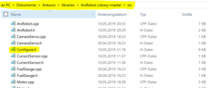
The .ino code now accesses the library, which contains several already existing, but also newly created classes. These are located under the following path:
The UML diagram should be used in the final post to understand the individual classes in the library. More details of the classes I have added will be added in the following sections Telemetry and Commands. However, there are still a few words about the Configure.h to explain.
This contains all important ID’s to communicate with the Arxterra App. Furthermore, the pins to which the different components of the Arduino are connected are defined here (except encoder pins – special case – see in this blog Telemetry section).
The Telecom class is the main component and performs all other classes to organize the data transfer. But here I don’t want to go into detail yet because I describe the implementation in the blogs Telemetry and Commands.
However, before reading these blogs, you should understand the blog about Custom Comands and Telemetry.
Commands
Commands can be created as custom commands or fulfill existing commands. Since the ArxRobot Control Panel already has an interface with some features, you should first go through the list of already existing commands. Among them the Configure.h is to be considered also in the src file of the library, since here the already implemented ID’s are to be found.
Move
How are the commands executed now? If the ArxRobot app sends a command with a command identifier, the function CommandHandler of the Telecom class is executed. This checks the Command ID and as soon as it matches the MOVE ID the object motor_driver of the SixWheelDiff class is executed. The other data is transferred to the function.
First some information about the Command Move. This was already implemented and only needed to be extended. The first expansion was the addition of 4 more motors. Since it was already clear that an electronic differential had to be implemented, I created a new class for it: SixWheelDiff.
The task of this class is to process the Move data and to forward it to the different motors. You can read more about the calculation in the 6-Wheel-Differential Blog.
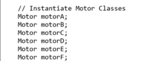
To do this, 6 motors must first be created as objects of the class motor (.h file).
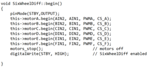
Then the pin information of the Configure.h file is transferred to the motors (.cpp file).
The motors_go method first examines in which case the robot is controlled by motion and then performs the respective differential calculation.
The calculated direction and speed is then passed on to the respective motor.
We take a closer look at the engine class. If an object is created, it first saves its attribute values/pins with which the motor is to work. If the method go() is called, it gets a speed in the form of a byte and the direction.
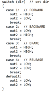
First, a case distinction is made, which switches the pins for the desired motor mode/direction.
This is followed by a PID controller, which is commented out. This has the background that the idea of a motor controller was first there, but we have found that almost exclusively at maximum speed/power on the engines is driven. In addition, differential turning did not cause any problems without speed control. If this controller is required in the future, however, its controller parameters must still be calculated.
We get the ACTUAL speed from the encoder and the SET value from the ArxRobot app. The constants Kp, Ki and Kd are to be set for the respective controller strength. Furthermore, the constant Ta is required, which stands for the sampling time (interval of the controller call).
The next section of code is needed for the unloaded state case. The current sensors work, but they are not sensitive enough to detect a current when the Pathfinder is driving on a smooth surface (hardly any power is needed there). It was then implemented as follows. First, a custom command button was introduced that activates or deactivates the unloaded state detection mode. This is stored here under the variable _check. If the unloaded state is now activated, the rear four motors are only operated at 0.8 times the speed and the front two at 1.4 times the speed. This has the effect that the power increases at the front motors and decreases at the rear motors and so a current is recognizable at the front motors at ground contact. But since the overall speed is minimally reduced, I made this mode a on and off case by creating a command on the control panel.
Unloaded State
As already mentioned, there is the unloaded state detection function. There is a Custom Command button in the Control Panel for this purpose.
This code only checks if the switch is activated or deactivated. The unloaded state variable is then passed on as a bool check to the respective methods of the individual motors, so that they can activate the function if desired.
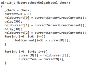
Now we go back to the motor. Before I begin to explain the code, I would like to mention again that the current sensors were not sensitive enough to detect the load on the motors when they move on a smooth surface. To improve the signal the following was done. First, the current is measured three times to avoid noise. However, the noise is suppressed over 8 measured values. However, since a delay must be created between each measurement, the old measured values will be used, so the interval time of the code call will be used as the delay. In other words, the delay used is the execution of other lines of code.
The total value is used as the sum under currentSum. A division by the number of values is not necessary, since it is only important whether the value is greater than 0 or assumes the value 0. This allows the code to be kept small. Now we get an acceptable exact value using the specially developed noise filter, but this does not improve the sensitivity of the current sensor, which ultimately led to the solution of the load increase of the front motors, as already mentioned.
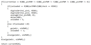
Next the function was programmed. Initially, this is only done if the motor is one of the two front motors. If currentSum now corresponds to the value 0, the motor must be stopped. A second If query also checks whether the mode is activated and whether the motor is running at all. Since the system was too sensitive for the current sensors, the code had to be designed more sluggish, so the unloaded variable now prevents the system from shutting down the engine too quickly if the unloaded state is detected. The idea is that the unloaded state must be detected five times before it finally intervenes and switches off the motor.
Switching off MUST be done directly and cannot work with the go() method, otherwise the speed set by the ControlPanel will be overwritten and the system has forgotten how to run the motor when the motor is activated.
The next challenge was how to see if the engine is already back on the ground. To detect this, the motor must be in motion, which is why the motor is started again and again after shutdown and the unloaded state can be detected again at the next check. This leads to a stop-and-go of the engine, which is necessary and unavoidable.
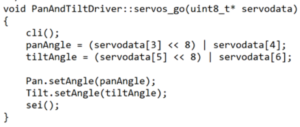
A further component of the commands are the servos, which are controlled with the ID SERVO_MOVE. As with controlling the motors, there is an interface class PanAndTiltDriver which transfers the data (angle) to the servo objects in an orderly manner. A 16 bit variable is also created from the two byte array per angle to enable 360 degree inclinations. The reason for this is that the ControlPanel only transfers data in unsigned bytes, but an unsigned byte has a maximum value range of only 255. That’s why we get two bytes per angle.
Now that the angle is available in a variable, it is forwarded to the servo object, which controls the servos via the Arduino Servo.h library.
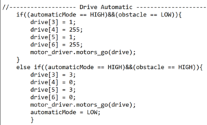
The last command is the AutomaticMode. This is the first step for automatic driving, but without waypoints. Unfortunately, there was only enough time for a simple straight ahead drive. As soon as the ultrasonic sensors detect an obstacle, the mode is switched off and braked. This means that the obstacle can be avoided in manual mode.
Telemetry
Now we come to the second component of the software – telemetry. In order to become aware of the hierarchy again, I recommend to study the UML diagram.
First, I want to describe how to insert a telemetry to send values of a variable to the Control Panel at all. Then I will explain how the individual telemetry values were calculated.
First, a packet must be created in the Telecom class. For this we usually use the name of the sensor type. As in the following example I create a package for the ultrasonic sensors. In order for the package to be identified by the Control Panel, an ID must be created in Configure.h, which is passed to the compiler when it is created.
Now the deviation and the interval of the update can be set if necessary. If this is not done, predefined values (Accuracy +-1 and SamplePeriod 1s) are used. It can be set as follows under the method begin() of the telecom class.
At last only the value has to be sent. This is done under sendData() in the telecom class as follows. First, the value must be calculated and stored in a variable. This variable is then sent via sendSensor(). Because sendData() is in a permanently called loop, this is always updated.
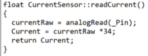
Now only the telemetry values have to be calculated, then the code is complete. Let’s start with the current sensors. These are calculated in their own class and called by the engine class. The value is read via an analog pin and only taken 34 times. Since the current sensor is in the motor shield, I used the calculation from the example class, which is provided by Pololu for the motor shield.
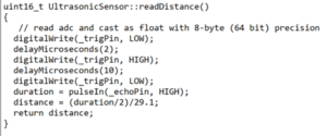
The ultrasonic sensor distance calculation was used by the test code of the previous generations and implemented into the own class as a method.
The encoders are read via interrupts, which is why the code is in the .ino code. The constant for the conversion of the interval time into RPM was determined by measurements during test drives.
Conclusion
Hopefully, this sums up the firmware side of what our generation of pathfinder completed this semester. The main improvements for the software for future generations is autonomous driving with waypoint navigation. This should get the next generation to the next phase of Pathfinder Chassis.


