Pathfinder Chassis – Current Sensor Test
October 3, 2018 / Pathfinder #6 / by Larry Vinh
Table of Contents
Introduction
The current sensor test is to check if the current sensors are giving accurate readings. If the reading from the sensors are accurate, then the sensors can be used to monitor current flow to the motor. We will be able to adjust the chassis if a particular motor is receiving too little or too much current. This test is also to check the previous generation’s current sensors. Due to the previous PCB short circuiting, the current sensors need to be tested to see if they are operational.
Parts Used:
- INA 169 Current Sensor
- Breadboard
- LED
- Arduino
- Resistor(s)
- Multimeter
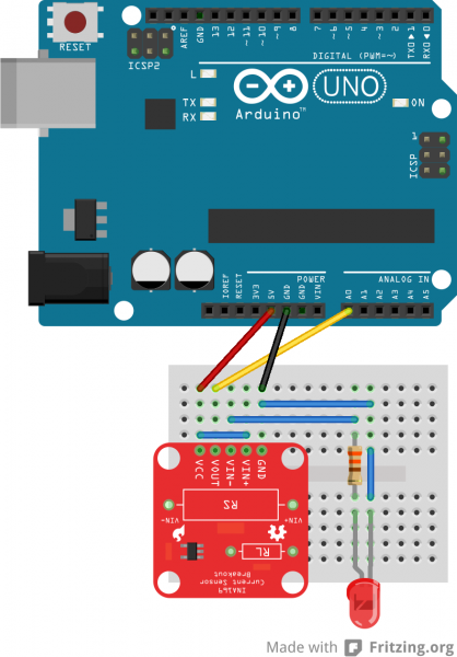
Figure 1: Fritzing Diagram for Current Test. See Reference 1.
Fritzing diagram for the Current sensor test. This will be used as a model of how the connections should be made from the current sensor to the Arduino.
Set-up:
For this experiment, 2 10Ω resistors, an LED, an ADK Arduino, the INA169 current sensor, and a breadboard were used. The resistors and LED are connected in series with VIN- from the current sensor connected to the high side of the resistor. The circuit and the GND pin from the current sensor uses the ground pin from the Arduino as their reference ground. The 5V from the Arduino is used to power the current sensor by connecting itself to the VCC pin and is used as the input by being connected to VIN+. Vout of the current sensor is used as an input to A0, so that the Arduino can use Vout to calculate the current of the resistor. The code below will calculate the current with the INA169 with RL= 10 kOhms and Rs= .11 Ohms. To verify whether the reading from the current sensor is accurate, a multimeter is connected in series with the resistor to verify that the reading from the arduino matches the reading from the multimeter.
/*
const int SENSOR_PIN = A0; // Input pin for measuring Vout
const int RS = .11; // Shunt resistor value (in ohms)
const int VOLTAGE_REF = 5; // Reference voltage for analog read
float sensorValue; // Variable to store value from analog read
float current; // Calculated current
Serial.begin(9600);}
void loop() {
// Read a value from the INA169 board
 sensorValue = analogRead(SENSOR_PIN);
// Remap the ADC value into a voltage number (5V reference)
 sensorValue = (sensorValue * VOLTAGE_REF) / 1023;
// Follow the equation given by the INA169 datasheet to
 // determine the current flowing through RS. RL = 10k
 // Is = (Vout x 1k) / (RS x RL) reduces to Is=Vout/(10*RS)
 current = sensorValue / (10 * RS);
// Output value (in amps) to the serial monitor to 3 decimal
 Serial.print(current, 4);
 Serial.println("A");
// Delays program for half a second
 delay(500);
}
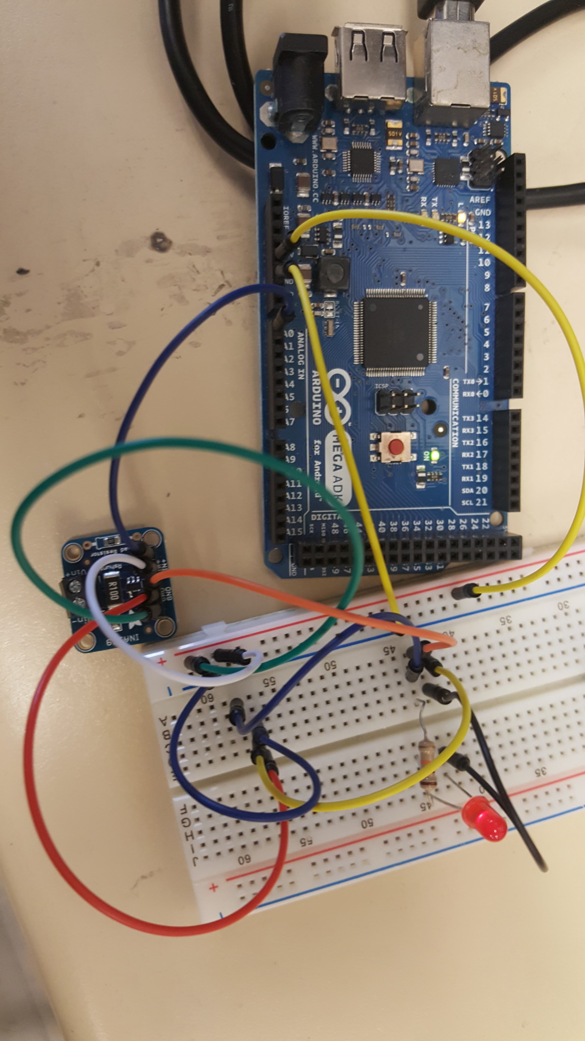
Figure 2: Implementation of the Fritzing Diagram.
This was the circuit was created based on Figure 1. The wiring is different because the current sensor used had female headers as opposed to the male headers in Figure 1.
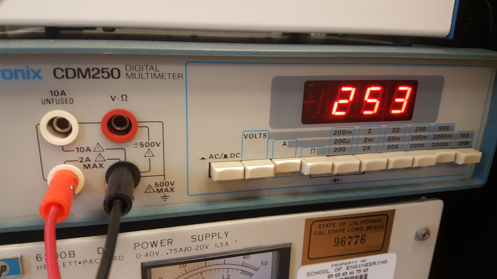
Figure 3: Measurement of the current from a multimeter.
The reading of the current through the surface using a multimeter. The reading from the multimeter will be used as a reference for the reading from the arduino. Reading is .253Amps.
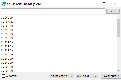
Figure 4: Reading from Current Sensor
Serial monitor output which is the reading the Arduino calculates. It gives the current in Amps and can be used with the reading from the multimeter to verify that current sensor gives accurate reading.
From comparing the measurement given by the multimeter to the one given by the current sensor, it can be seen that the difference between the reading is very minor. The percent error between the two measurements is calculated to be about 2.4%. The output from the serial monitor shows that the current sensor is functioning because it gives a Vout.
Conclusion:
From conducting the test, the current sensors were shown to give an accurate measurement of the current. This will allow us to use the current sensors to accurately monitor the load on the motors. Then, we will be able to determine whether a motor is under no load. If it is under no load, then the Chassis will adjust itself to be correctly positioned. The other result from conducting these test is the previous current sensors were discovered to give no reading. New current sensors were ordered to replace them, and after running this test, the new current sensors were found to be operational.