Pathfinder S’17 – Preliminary Design Documentation
Project Team:
Daniel Vergara (Project Manager)
Abdullah Albelbisi (Mission Systems & Test)
Renpeng Zhang (Electronics & Control)
Edgardo Villalobos (Design & Manufacturing)
Anthony Dunigan (Design & Manufacturing)
Program Objective / Mission Profile
Program Objectives
By Daniel Vergara (Project Manager)
The program objective statement sets goals for the Spring 17 Pathfinder that previous semesters could not accomplish in time. Although the Pathfinder S’17 is an inherited project, major improvements are necessary to accomplish goals that have been long overdue. The Pathfinder S’17 will be able to articulate each of its 3 solar panel wings towards the sun to maximize solar power absorption and charge the battery, all the while providing modular solar panel voltage levels, charging currents, articulation angles and battery fuel levels. The Pathfinder will be capable of entering and exiting a cocoon state while at rest and before traversing steep terrain. The Pathfinder S’17 will demonstrate superior rocker bogie suspension to conquer any terrain at a height equal to that of the wheels’ diameter. When traversing Earth land, the Pathfinder will also demonstrate electronic differential slip turning, obstacle avoidance, and autonomous GPS navigation. None of the aforementioned improvement adjustments shall preclude future High Desert operations, namely: AC unit, pan/tilt platform, or wheels.
[Updated 3/5/17]
Mission Profile Statement
By Daniel Vergara (Project Manager)
The Mission Objective is to traverse the same course defined for the Fall ’16 Pathfinder which begins in front of the CSULB Library’s main entrance ( 33°46’39.0″N 118°06’51.5″W) and complete at a solar panel charging station .09 miles away (33°46’40.7′′N 118°06’48.9′′W). The Pathfinder will begin in it’s cocoon state and transform into it’s mobile state with solar panels extended. While traversing the course, the Pathfinder will demonstrate differential -slip turning capabilities, autonomous GPS navigation, proper rocker-bogie mechanics, and dynamic solar panel articulation in order to track the sun. Telemetry including battery fuel level, charge absorbed, and solar panel voltage levels will be available.
[Updated 3/5/17]
Requirements
Lvl 1 Requirement Analysis Rubric
By Daniel Vergara (Project Manager)
A lvl 1 requirement analysis of previous semesters is beneficial to conduct since the same mistakes can be avoided when producing new lvl 1 requirements in an effort to improve upon previous semester’s projects. Failure to accomplish Program Requirements are often a result of poor lvl 1 requirements, thus it is crucial to begin the project with sound high-level requirements.
In this section you will find a table of analysis based on the following 9 rubric questions, one for Pathfinder – Solar Panel project and also one for Pathfinder – Chassis project.
- Is the requirement, Quantitative, Verifiable, and Realizable?
- Is the requirement located at the correct level (1 – Program/Project, 2 – System/Subsystem)
- Is the requirement response to a higher level requirement or customer’s objective (Requirement Flow Down)? Is the linkage clearly defined?
- Does requirement provide links to source material?
- Does the requirement move the design process forward?
- Are equations used to calculate a requirement provided and are answers correct?
- The requirements that are missing are the hardest to discover and will be factored into your evaluation.
- Is language in the form of a requirement?
- Avoid multiple requirements within a paragraph. (i.e., breakup statements that contain multiple requirements)
Fall ‘16 Solar Panels Lvl 1 Requirements Analysis
By Daniel Vergara (Project Manager)
| Level 1 Requirements | Requirement Rubric Question Number | ||||||||
| (Fall 16′ Solar Panels) | 1 | 2 | 3 | 4 | 5 | 6 | 7 | 8 | 9 |
| A. The Pathfinder shall be self-sufficient using solar panels. | N | Y | Y | N | N | N | – | Y | N |
| B. The solar panels shall be able to enter and exit a cocoon state. | N | Y | Y | N | Y | N | – | Y | N |
| C. The Solar Panels will have a fixed north/south orientation for the panels to track the east to west movement of the sun. | Y | Y | Y | N | Y | N | – | Y | Y |
| D. The form factor of the Solar Panels shall be identical to that of the Spirit and Opportunity | Y | Y | Y | N | Y | N | – | Y | Y |
| E. The Pathfinder will be able to fit into the east most cabinet in ECS – 317. | Y | Y | Y | N | N | N | – | Y | Y |
| F. The Pathfinder shall have requirements agreed between both the Solar Panel and Chassis group within the Interface Control Document (ICD). | Y | Y | Y | N | Y | N | – | Y | Y |
| G. The Pathfinder should be able to ride itself back up using the side Solar Panels and Custom Command; Cocoon. | N | Y | Y | N | N | N | – | Y | Y |
| H. The expenses of the Solar Panel system should be limited to $200. | Y | Y | Y | N | Y | N | – | Y | Y |
| I. The Solar Panel System shall be completed by December 14, 2016. | Y | Y | Y | N | Y | N | – | Y | Y |
| J. The Solar Panel system shall use a custom PCB. | Y | Y | Y | N | Y | N | – | Y | N |
| K. The Solar Panel system shall use custom commands. | Y | Y | Y | N | Y | N | – | Y | Y |
| L. The Solar Panel system should use custom telemetry. | Y | Y | Y | N | Y | N | – | Y | Y |
As a summary of the above analysis, the following points are given regarding last semester’s solar panel lvl 1 requirements:
- Each requirement did not give an equation nor a source. If a source was posted, it was not given near the requirements. Yet, some do not require equations or sources since they come directly from the customer. Use of “self-sufficient” is vague and does not appear to be verifiable nor quantitative. Since it does not define what it means for the solar panels to be self-sufficient, it does not move the design process forward and should be broken down into separate requirements discussing the battery and means of charging.
- “Cocoon state” is not defined and is therefore not verifiable. This can be broken down into more descriptive requirements.
- See A.
- See A.
- This requirement does not move the design process forward since it doesnt say how it will fit in the cabinet. Further research is needed to determine cabinet dimensions
- See A.
- “Ride itself back up” is vague and does not move the design process forward
- – L. See A.
Fall ‘16 Chassis Lvl 1 Requirements Analysis
By Daniel Vergara (Project Manager)
| Level 1 Requirements | Requirement Rubric Question Number | ||||||||
| (Fall 16′ Pathfinder Chassis) | 1 | 2 | 3 | 4 | 5 | 6 | 7 | 8 | 9 |
| A. The pathfinder shall be autonomous, demonstrating GPS navigation mode on Arxterra | Y | Y | Y | N | Y | N | – | Y | N |
| B.The pathfinder shall avoid obstacles articulating Ping Ultrasonic Range Finder and a LiDAR sensor | Y | Y | Y | N | Y | N | – | Y | Y |
| C. The pathfinder shall implement digital slip differential for turning, i.e., inside wheels turn at a different speed than the outside wheels while turning | Y | Y | Y | N | N | N | – | Y | Y |
| D.The six wheels shall be on a rocker bogie suspension system to allow the Pathfinder to traverse through rough terrain and enable mobility | N | Y | Y | N | N | N | – | Y | Y |
| E.Each wheel shall have its own motor in order to be able to be controlled independently | Y | Y | Y | N | Y | N | – | Y | Y |
| F.Wheels under no load condition shall stop spinning in order to conserve power | Y | Y | Y | N | Y | N | – | Y | Y |
| G. The physical design of the Pathfinder shall mimic the Spirit and Opportunity rovers. | N | Y | Y | N | Y | N | – | Y | Y |
| H. The pan and tilt system shall be modified to support an Android phone | Y | Y | Y | N | Y | N | – | Y | Y |
| I. The pan and tilt system shall be sealed in order to protect it from weather conditions in December | N | Y | Y | N | Y | N | – | Y | Y |
| J. The Pathfinder shall explore the course defined by the AdBot rover. The mission shall be completed in 4 hours in the evening. | Y | Y | Y | N | Y | N | – | Y | N |
| K.The Pathfinder shall be completed by the last day of 400D course, December 15th, 2017 | Y | Y | Y | N | Y | N | – | Y | Y |
As a summary of the above analysis, the following points are given regarding last semester’s chassis lvl 1 requirements:
- As with the previously analyzed requirements, each one from this set does not clearly provide source material nor provide equations. GPS navigation and the robot being autonomous seems like it should be separated into two requirements.
- See A.
- This does not move the design process forward, since it just mentions a slip differential but nothing on how to implement it.
- “Rough terrain“ is not defined, therefore it is not quantifiable nor verifible and does not help to move design forward. A mention of the height of terrain may be helpful.
- See A.
- See A.
- Although it gives reference to a rover it will mimic, it will most likely not be identical and should specify areas where it will try to closely capture the rover’s design
- See A.
- “December weather conditions” is not defined therefore it may pass a test but may not satisfy customer objectives.
- Can be broken into two requirements.
- See A.
Lvl 1 Program/Project Requirements
By Daniel Vergara (Project Manager)
1.) Pathfinder shall begin course at 33°46’39.0″N 118°06’51.5″W and travel .09 miles to its charging station at 33°46’40.7′′N 118°06’48.9′′W, along the way traversing along mostly flat grass and pavement. In addition the course involves traversing down a set of 3 stairs with each step at a downward slope of 70o, and up an identical set of 3 stairs with each step at an upward slope of 70o.
Sources: Fall 16 Solar Panels , Fall 16 Pathfinder Chassis CDR
2.) Before beginning course traversal, Pathfinder shall launch from cocoon state which is defined by both side panels being manually folded with their respective lower halves onto their upper halves, both side panels utilizing a worm gear mechanism to fold upward toward the sky each at an angle of 85o with respective to the flat solar panel base, and the butt panel also utilizing a worm gear mechanism to fold upward toward the sky at angle of 85o.
Source: Fall 16 Solar Panels Design
3.) Pathfinder shall allow user to manually execute “enter cocoon state” program module via Arxterra App to enter into cocoon state at any time, especially before traversing estimated steep terrain(45o degrees or greater). The “enter cocoon state” program module will be available after each side panel has been manually folded in half.
4.) Pathfinder shall allow user to manually execute “exit cocoon state” program module via Arxterra App to exit cocoon state at any time, specifically to begin course traversal. Exit cocoon state” is only executed while the Pathfinder rests in “cocoon state”, allowing both side panels and the butt panel to fold downward towards the ground starting from 85o and to an angle of 210o relative to the solar panel base, whereafter, the user shall manually complete the “exit cocoon state” sequence by unfolding each side wing at their respective halves.
5.) Pathfinder shall allow user to execute “articulate state” program module which is available after the Pathfinder has completed the “exit cocoon state” sequence in order to articulate the solar cells directly at the sun to maximize energy absorption, limited to the full bend of each wing, which is between 210o and 85o relative to the solar panel base. Articulate state is based on an “articulate state” program module which precisely actuates each wing’s stepper motor attached to a respective worm gear mechanism based on the program module’s parameters which include time of day, GPS location, orientation, and local sun trajectory.
6.) Pathfinder shall provide updates of solar panel articulation angles which come from the “articulate state” program module.
7.) Pathfinder will provide solar panel voltages and charging current by capturing each modular panel’s electrical output separately.
8.) Two side panels, a butt panel, and a base panel shall be modular by wiring three 6V cells in parallel and encapsulated them one panel at a time. They will then be wired in series to create a 24V supply to the battery.
Source: 6V Solar Cell
9.) Form factor of the solar panels will be identical to panels on the Spirit and Opportunity MERs, which, when scaled, encompasses no more than 19” x 34” x 26”.
Source:Fall 16 Solar Panels Design
10.) Electronic slip differential 6-wheel drive shall be implemented by an “eSD” program module, based on calculations related to turning angle, to allow outside and inside wheels to rotate at different speeds by means of three VNH5019 motor drivers to control each motor along with a PCA96805 I/O expander and a hex inverter.
Source: Fall 16 Motor Control
11.) Wheels that are not in contact with terrain shall be actuated by “eSD” program module to stop spinning by using current sensing shunt resistors reporting currents that match free-spinning wheel characteristics.
Source: Fall 16 Current Sensor Experiment
12.) Pathfinder shall demonstrate obstacle avoidance during course traversal by articulating 2 Lidar sensors via pan and tilt system. These Lidar sensors will provide input and be controlled by the “Waypoint Navigation” program module used during the Fall ‘16 semester.
Source: Fall 16 Waypoint Navigation
13.) Pathfinder will utilize “Waypoint Navigation” program module for autonomous GPS navigation during course traversal by naming 8-12 points along the course in between start and finish locations. Points are defined by points at which the Pathfinder changes direction.
Source:Fall 16 Waypoint Navigation
14.) Pathfinder shall not hinder future use of Pathfinder in high desert conditions by modification of wheels, pan/tilt platform, and AC unit.
15.) Rocker bogie system shall be improved by closely modeling the suspension mechanics behind the Mars Exploration Rovers, Curiosity and Spirit.
Sources: Rocker Bogie Design Resource 1 , Rocker Bogie Design Resource 2
16.) Pathfinder shall be ready to demonstrate Mission Profile and Project objectives by May 12th, 2017.
[Updated 3/5/17]
Lvl 2 System/Subsystem Requirements
By Abdullah Albelbisi ( Mission Systems and Test Engineer) & Daniel Vergara (Project Manager)
1- Wheels that are not in contact with terrain shall endure zero load and stop spinning by using wheel control system using a Torquedetector
2- Pathfinder shall demonstrate obstacle avoidance during traversal by using articulating 2 Lidar sensors via pan and tilt system and two SeedStudio ultrasonic range finders part number (SEN136B5B)
3- Rocker bogie system shall operate similar to MERs to traverse rough terrain and steps no larger than diameter of wheel, which is 6 inches by using bigger wheels (TBD), DC motor, and legs.
4- Battery charge time and voltage levels shall be stored, based on solar panel efficiency and sun energy available during time of course traversal using battery measurement circuit.
5- Two-axis open loop system will be operated by two 12V, 2-3A DC motors capable of 50 oz/in of torque based on solar panel weight, and actuated by an algorithm presented by Grena which is able to calculate position of sun with an error of .0027o, which will be present in on board MCU firmware to optimize photo energy absorption.
Sources: Lee, Chou, Chang, Lee. Sun Tracking Systems: A Review (Online). Available: https://www.ncbi.nlm.nih.gov/pmc/articles/PMC3297124/#b49-sensors-09-03875
http://arxterra.com/fall-2016-solar-panels-motor-trade-off-study/
6- Articulation angles, generated by aforementioned Grena algorithm, panel voltages, charging current, and battery fuel level coming from circuit measurements shall be given as single number outputs, easily readable by an Arxterra user.
7- Pathfinder shall commence Mission Objective Start by transferring from cocoon state, of dimensions less than 19” x 34” x 26” , to mobile state by utilizing 5 worm gear mechanisms which operates at a 30:1 gear ratio, exerting no load torque when not in use because of worm gear locking mechanism, and capable of exerting torque at 440z./in. by NEMA 17-size hybrid stepping motors.
Sources: http://arxterra.com/fall-2016-solar-panels-folding-mechanism-trade-off-study/
8- Form factor of solar panels shall closely follow last semester’s measurements and design which are modeled after MERs Curiosity and Spirit. Also, the encapsulation of solar panels via plexi-glass will not compromise current fit.
Sources: http://arxterra.com/form-factor/
9- The Pathfinder shall utilize eLSD to drive 6-wheels independently .18 miles round trip to 33°46’40.7″N 118°06’48.9″W and back. Wheel circumference and distance to be traveled, and angle of turn relative to each wheel will act as inputs in order to determine RPM to be assigned to each wheel.
a. Wheel diameter (6in.) x pi = Circumference ( 18.85in)
b. Revolutions to be actuated= Distance ( variable ) / Circumference(18.85in)
Design Innovation
Creativity Review
By Daniel Vergara (Project Manager)
In an effort to meet customer requirements by any means, our Pathfinder Project Team undertook a creative brainstorming exercise where every creative idea was considered plausible. We began by defining two problem statements, defined below, upon which to focus our brainstorming activities. Since our problems do not define first iteration problems, but rather 5th or more, since our design is inherited, our creative solutions Our team practiced the following creativity exercises in order to provoke solutions for the defined problems.
Problem Statements:
A.) How can the solar panels track the sun?
B.) How can we improve on the rocker bogie system?
Creativity Exercises:
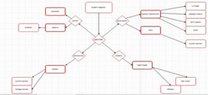
- Duncker Diagram
- Brain-writing Approach
- Attributes Listing
- Forced Relationship
- Point of View
Creative Solutions:
A.) Linear Actuators may require constant current which may drain battery, if so; add to strength of screw mechanism to articulate panels. Implement internal clock, and compass to calculate location of sun and algorithmic articulation firmware.
B.) Improve DC motor actuator firmware to work smarter with terrain. Increase smoothness and agility by optimizing functionality of rocker and bogie pivot points. Seamlessly integrate eLSD that does not compromise Rocker Bogie suspension system.
Source Material:
Creativity Exercise Guidelines
Pathfinder S’17 Creativity Powerpoint
Design and Unique Task Descriptions
By Daniel Vergara (Project Manager)
Electronics and Control Engineer Tasks
The majority of the electronics of the Pathfinder and solar system will be inherited from last semester. The systems and subsystems will not change with the exception of additions to meet customer’s needs for this semester. Additions and improvements in regards to electronics and control and the tasks needed to move the design process forward are as follows:
- Control motors to actuate solar panel articulation system
- Understand last semester’s design and actuation
- Circuit Design Layout(Fritzing Diagram)
- Solar cells are modular and can independently charge the battery
- Research solar panel circuitry
- Circuit Design Layout of solar cells/panels(Fritzing Diagram)
- Allow for charging of battery from solar panel voltage
- Research Solar Panel Circuitry
- Understand how to supply solar panel voltage to battery
- Provide efficiency given solar panels and battery being used
- Circuit Design Layout of solar panel + battery(Fritzing Diagram)
- Interpret and report charge supplied to battery, battery fuel levels, and solar panel voltage levels to controller
- Research solar panel to controller communication experiment from last semester
- Voltage/current sensor tradeoff study
- Implement chosen sensor into circuit
- Electronic limited slip differential implementation
- Research eLSD
- Layout equations used by the code for 6-wheels to turn at 300,45o,60o
Design & Manufacturing (Solar Panels) Engineer Tasks
The same format factor will be used as last semester for the solar panels. It is a customer requirement that each solar panel cell be modular, allowing the solar panel unit to function properly if one solar cell malfunctions. The solar panels are to be encapsulated as well. This can be done by choosing market modular cells that are already encapsulated. Design and Manufacturing related tasks according to new customer requirements are as follows:
- Research modular cells that can be bought online
- Form factorize cells onto existing panel dimensions
- Explain how cells attach to solar panel frame
- Tradeoff study among different ways of connecting cells to create modular panel
- Tradeoff study between buying market encapsulated modular cells vs. encapsulating cells with snap-on plexi glass cover
- 3D model individual cell
- 3D model panel as a whole
- Research/tradeoff study of sun tracking system
- Light sensors vs. fixed sun tracking based on time of day/date/and compass
Design & Manufacturing (Chassis) Engineer Tasks
The same chassis as last semester shall be used. The rocker bogie system modeled after the MERs, as a program requirement, is expected to function properly. Last semester’s suspension system encountered slipping while the wheels were not in contact with the ground, so this needs to be fixed. Also, the suspension system should move with better agility and smoothness. Last semester’s suspension did not respond to terrain well and was prone to tipping over when encountering steep terrain. The Manufacturing Engineer focusing on the chassis/rocker-bogie system design should accomplish the following tasks:
- Understand how last semester’s rocker-bogie system design was not implemented properly
- Become an expert on MERs modeled rocker-bogie system enough to give presentation to class in coming weeks
- Understand how to improve upon current rocker-bogie system
- Effect of adding a stopper to back pivot
- Effect of no-load on wheels during slipping
- Other improvements
- 3D model of improvements
System/Subsystem Design
Product Breakdown Structure
By Abdullah Albelbisi (Mission Systems and Test Engineer)
Electronic System Design
System Block Diagram
By Abdullah Albelbisi (Mission Systems and Test Engineer)
Electronic Design By Task
By Renpeng Zhang (Electronics and Control Engineer)
As the electronics and control engineer, my task is to come up with a solution on the mechanism of how the solar cell would charge the battery. Doing trade off studies on motors to explore all the options. Research of voltage and current sensor for tracking the voltage and current provided by the solar panel. Come up with solutions on the power level measuring device for the battery. And research on the circuitry of the solar cell layout.
- Control motors to actuate solar panel articulation system
Trade off study on DC motor and stepper motor
DC motor
- Requires only two wires(power & ground)
- Controlled using PWM which is more efficient
- It will have better efficiency because of PWM control
Stepper motor
- Requires external control circuit such as Arduino
- Uses multiple toothed electromagnets arranged around a central gear to define position
- Has better precision and easier to control
Due to the precision control and being able to be controlled by the Arduino board, we’ve decided to use the stepper motor to control our solar panel articulation system.
Sources:
http://arxterra.com/fall-2016-solar-panels-dc-motor-with-encoder-experiment/
http://arxterra.com/fall-2016-solar-panels-motor-trade-off-study/
https://www.quora.com/What-is-the-difference-between-a-DC-motor-a-servomotor-and-a-stepper-motor
- Solar cells are modular and can independently charge the battery
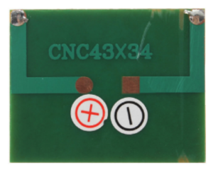
Research found me that PWR1241 for small individual solar cells.
Specifications
- Output voltage: 4.5 VDC
- Current: 90 mA
- Dimensions: 2.38″ x 2.38″ x 0.1″ (60mm x 60mm x 2.56mm)
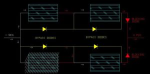
Solar cells can be connected in series to increase their voltage output. Have a multiple of solar cells in parallel with blocking diode with blocking diode; if one of the solar cell is shaded, it will still produce 24 V from the other solar cells in series and prevent back feed.
Sources:
http://www.instructables.com/id/Connecting-Multiple-Solar-Panels/step4/step4/
- Allow for charging of battery from solar panel voltage
Charging the solar cell to the battery sample circuit.
Gather current and voltage levels from solar panels
- Thinking of using the ACS712 current sensor
- It’s capable of measuring from mA up to 50 A
- Video of ACS712 in sources
- Thinking of using the FZ0430 voltage sensor
- Will measure 0-25 V
Sources:
http://www.evilmadscientist.com/2008/simple-solar-circuits/
ACS712
FZ0430 voltage sensor
- Electronic Slip Differential
- Performs the same tasks as normal limited slip differential
- Often uses pressurized hydraulic clutches
- Make sure each wheel is receiving sufficient torque by the use of electronic control unit
- Send battery fuel levels to controller
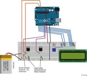
- Found the fritzing diagram for measuring power level for the battery
- Going to build the device according to the above fritzing diagram
Sources:
http://www.instructables.com/id/Arduino-cell-capacity-meter/step3/The-Circuit/
Mechanical Design
Mechanical Solar Panel Design By Task
By Edgardo Villalobos (Design and Manufacturing Engineer)
As the Manufacturing Engineer for the solar panels on the Pathfinder, I am required to come up with a solution in articulating the solar panels used in the previous semester. From their trade-off studies, they found that the worm gear system that they had used was the most efficient way of doing the articulation and cocooning in order of saving power and current flow. The problem with last year’s model came down to sizing. It had a difficult time closing all the way due to the small size of gears not being able to get around the encapsulation.
Another thing we want to work on is the solar cell encapsulation because we’d like to find a way to make these cells modular so that a cell can easily be replaced.
ENCAPSULATION TRADE OFF STUDY
PLEXIGLASS
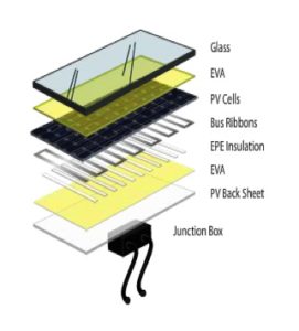
Plexiglass provides a lightweight, about 3 lbs per 8 sq. ft. with a 0.065 thickness, anti-reflective surface and is classified as a scratch resistant surface. Although plexiglass is virtually impossible to break and scratch resistant, it can scratch much easier than glass. If this material is used to encapsulate solar cells, we’d be able to acquire it from Home Depot or other similar store. This glass would then be used to cover the entire panel. To get the right shape out of the glass, we could use a dremel grinder to cut to size. The size of the glass would be the same size as the panels, which still need to be measured. The downside to using plexiglass is that each solar cell needs to be sandwiched using other materials, such as resin, which costs more.
Source:
[1]Plexiglass
[2]Materials
[3]Materials
http://www.dunmore.com/products/solar-back-sheet.html
EPOXY COVERED SOLAR CELLS
Solar cells could be bought already encapsulated with a UV resistant epoxy and are usually meant to charge phones. Each cell is independently encapsulated making it easier to remove and add new cells. These cells are also polarity based, which could require wires instead of tabbing wires, also making it easier to switch cells. Using these cells would cost about the same as buying all the materials, using the plexiglass sandwich method.
Mechanical Rocker-Bogie Design By Task
By Anthony Dunigan (Design and Manufacturing Engineer)
For this semester’s rocker-bogie design, I am required to improve the system. But in order to understand the system the Rocker-Bogie System must be understood. So a short explanation of how it works will be given below.
How the Rocker-Bogie Suspension Works
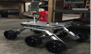
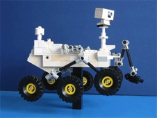
The rovers have 6 wheels and a rocker bogie suspension system that allowed it to drive smoothly over rough terrain. On each side of the rovers are individual rocker bogie assemblies. The rocker is the larger portion of the system which is connected to the chassis of the rover. The rocker pivot is what connects the rocker to the chassis. The bogie portion is the smaller leg of the system. And it is connected to the rocker. The bogie has wheels on both ends. Each of the six wheels have their own motor.
The rocker bogie system or the mechanism keeps the rover’s body level. This occurs due to a mechanism called the differential. The differential is keeps the rover’s body level by keeping the body angle of the rover halfway between the angles of the two rockers. So when one of the rockers goes up the other rocker goes down to keep it level. There are two different mechanisms that make it work and they are a differential gearbox or a differential bar.
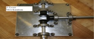
The differential gear box was used on the Mars Exploration Rovers (Spirit and Opportunity). The gear box is located within the chassis. The gear box within the Mars Exploration Rovers (MER) were very complicated and had a large amount of gears. So for simplicity, a 3 gear differential will be explained. For a 3 gear differential, 2 of the gears would be connected to each of the rocker pivots. The 3rd gear will be perpendicular to the other 2 gears but in contact with them. As one of the rockers goes up the gear within the chassis connected to that rockers pivot will rotate causing the other gear that is in-between the 2 gears to rotate. And which will cause the gear that’s attached to the opposite rocker pivot to rotate the opposite of the other gear or down.
The differential bar mechanism used in the Mars Science Laboratory (Curiosity Rover) is set up different then the differential gear box mechanism but works the same way. The bar mechanism has bar that is connected above the chassis or body of the rover. The bar is connected to the two rocker pivots through short links. So as one of the rockers goes up or down the bar tilts with respect of the rockers and causes the opposite rocker to go the opposite direction. The set back with the differential bar is that it is placed on top of the chassis.
A setback for the differential bar mechanism is that it will not allow anything to be placed on top of the chassis such as a solar panel. By setting the differential bar behind the chassis may accomplish this feat. The rocker bogie system does not use springs. No springs helps keep all six wheels on the ground with approximately equal pressure on each wheel which is good for a soft terrain such as sand. Below will be an explanation
Problem Statement
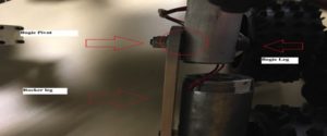
According to Fall 2016’s Pathfinder, the problem to be worked on would be to add a stop to the bogie pivot. They suggested that pivot motion should be limited in order go up obstacles. The problem I see the suspension system is that the bogie pivot is not allowed to move freely. I see that there is a small amount of spacing between the rocker legs and where the bogie pivot should be. The previous semester’s group also suggested the system is sufficient enough to improve on.
Solution Statement
The immediate solution would be to improve the movement of the joint since the joint appears to get stuck when it reaches a certain range of motion. The bolt that is be using to cause the pivot freely is called a shoulder bolt. The shoulder bolts are used for joint movements. The issue with the previous semester’s bogie pivot was that there was not enough spacing in between the rocker legs and the bogie leg as shown below.
These two legs may come in contact when the pivot is rotating. By increasing the spacing in between the legs the bogie may be able to rotate around the bougie pivot more freely. This would be accomplished by increasing the amount of washers used. The washers would be placed in between the rocker leg and the bogie legs. A ball bearing washer may be used to reduce the amount of friction so that the bogie may move more freely. By implementing this solution, I believe that the issue with Rocker-Bogie Suspension system should work.
Sources:
[1] Rocker Bogie System
http://www.alicesastroinfo.com/2012/07/mars-rover-rocker-bogie-differential/
[2] Ball bearing washers
https://www.motionindustries.com/taxonomy/Bearings/Ball%20Bearings/Ball%20Thrust%20Bearings%20&
%20Washers/browse/en

