PCB Design: Schematic – Spring 2016
Posted by: Luis Valdivia(Project Manager)
Written by: Kevin Nguyen(Electronics and Controls)
Table of Contents:
- Introduction
- Full EagleCAD Schematic
- Step-Down(Buck) Switching Regulator
- Servo Status Indicator
- PCA9685 Connections
- 3-Pin Headers for Servos and Lightshow
- Pin Headers for Low Voltage Alarm and Bluetooth
Introduction:
One of the main tasks of the Electronics and Controls Engineer is to design the circuit for the PCB. This post will explain the reasonings behind the chosen components on our PCB.
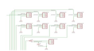
Fig 1.1 Full EagleCAD Schematic
This is the full schematic for UFO Quadcopter’s PCB. Further detail will be shown in the following figures.
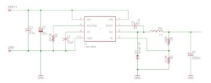
Fig 1.2 Step-Down(Buck) Switching Regulator
Tasked with redesigning the PCB from last semester, I chose to replace their adjustable LDO voltage regulator with an LMR14050 buck converter. The reason for this is because LDO regulators lower voltage by burning excess power while buck converters lower voltage by storing the excess power. For the quadcopter’s circuit, a 5V output is required from a 14.8V supply. Dropping that much voltage using an LDO will waste a lot of power. Using the buck converter, the supply voltage will be able to drop down to 5V while maintaining enough current to power the PCA9685, servos, and light show. Capacitors are placed in parallel with the input and output to smooth the ripples since switching circuits may cause some fluctuation. The inductor is a storage device used for storing energy. The size of the inductor will determine the current output of the buck. The LMR14050 can output a maximum of 2A, which will be enough to power the servos and light show. The resistor network on the right side of the buck is used to adjust the voltage. The values I used will result in a regulated 5V output.
Fig 1.3 Servo Status Indicator
This is a simple LED status indicator. It is connected to the same node that powers the servos. If the LED is lit, the servos should be powered on. The resistor is used to lower the current to protect the LED. With a constant voltage of 5V, the higher the resistance the lower the current.
Fig 1.4 PCA9685 Connections
The PCA9685 is the same chip used within the Adafruit Servo Driver. Since weight is a major issue for our project, I chose to implement the servo driver in our PCB so that we won’t have to add a third board to our setup. The left side of the PCA shows the connections for power and input. The right side is the PWM outputs for controlling the servos and light show. The PCA is connected to the MultiWii through I2C. The MultiWii is the master device and the PCA is the slave device. The Serial Data and Serial Clock signals from the MultiWii will be able to control all 8 servos and light show. The A0-A5 pins are used to set the address of the PCA. Since we are only using 1 slave device, I grounded all addressing pins which would set the PCA address to 0.
Fig 1.5 3-Pin Headers for Servos and Lightshow
8 3-Pin Headers are included for the servos. 4 for the servos rotating in the X direction and 4 for the servos rotating in the Y direction. A 3-Pin Header is also used for the light show. Each header includes a pin for data, power, and ground. The control signal will be coming from the PCA9685. These components will be powered by the regulated 5V from the buck.
Fig 1.6 Pin Headers for Low Voltage Alarm and Bluetooth
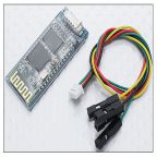
To keep things nice and tidy, I made pin headers on the PCB for the voltage alarm and the bluetooth module. This will hold all the components on the board and keep things from swinging around during flight.


