Sojourner/Spring/2019
Pololu Magnetic Motor Encoder Code and Set-Up Guide
Author/s: Cole Bailey (PM)
Table of Contents
Introduction
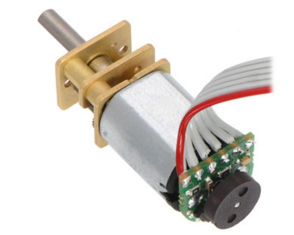
This blog post is a guide from start to finish on how to implement Pololu Magnetic Motor Encoders on to a Pololu Motor. Included will be recommendations to make the process easier and the code to count revolutions and display RPM of the motor. All of the information will come from the Pololu website or my experience making the encoders work. The code was originally designed to be used for differential turning, but can be applied to anything that requires RPM feedback.
Implementing the Encoder on the Motor
The Pololu Website has a detailed description of how to install your motor encoders here:
Here is a quick summary:
- Ensure that you order Pololu Extended Shaft Motors. If the motors do not have an extended shaft, you can not install the encoders.
- Solder the wires on to the encoder before soldering the encoder on to the motor to make your life easier.
- Terminals for the wires do not fit 22 AWG wires. We used 26 AWG wires.
- Color coding wires is helpful.
- If you would like to use a connector, you need to use a 6 pin 2mm-pitch connector. The encoder will not work with the common .1 inch connectors.
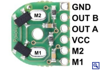
- Solder the encoders terminals labeled M1 and M2 onto the two power prongs coming from the motor.
- Ensure that the motor shaft is centered in the encoder so it does not rub on the sides.
- Using a “Helping Hand” is extremely helpful for holding the motor still.
- Attach the magnet on the end of the extended motor shaft after the encoder has been installed.
The Code
This is a very basic code that uses the hall effect sensors on the encoder. The Pololu encoder has two hall effect sensors connected to terminals Out A and Out B which need to be connected to interrupt pins on your micro-controller. The code provided only requires 1 of the hall effect sensor outputs, and only counts revolutions in total. The code does not take into account the direction. We chose to only use 1 hall effect sensor to free up space inside of the body of the Sojourner. Eliminating 1 wire from all 6 motors improves the maneuverability and aesthetics. The code provided below includes interrupts for all 6 motors that we are using, but only displays the count for two of the motors. You can modify the code to account for however many motors you use. You will have to modify the pin definitions to account for whichever micro-controller you are using. For this example we are displaying motor 1 an motor 2 because the Arduino Micro only has 2 interrupt pins (2, 3).
Here is the code:
/* This code is meant to read RPM of motors to allow control feedback to incorporate differential turns.
* Depending on the number of Interupt pins on the 3DoT, we may only monitor 2 motors and link the rest.
*/

//ticks of the right and left encoder. This is volatile so that it doesn't interfere with the rest of the code.
volatile unsigned long ticksM1 = 0;
volatile unsigned long ticksM1_old = 0;
volatile unsigned long RPM_M1 = 0;

volatile unsigned long ticksM2 = 0;
volatile unsigned long ticksM2_old = 0;
volatile unsigned long RPM_M2 = 0;

volatile unsigned long ticksM3 = 0;
volatile unsigned long ticksM3_old = 0;
volatile unsigned long RPM_M3 = 0;

volatile unsigned long ticksM4 = 0;
volatile unsigned long ticksM4_old = 0;
volatile unsigned long RPM_M4 = 0;

volatile unsigned long ticksM5 = 0;
volatile unsigned long ticksM5_old = 0;
volatile unsigned long RPM_M5 = 0;

volatile unsigned long ticksM6 = 0;
volatile unsigned long ticksM6_old = 0;
volatile unsigned long RPM_M6 = 0;

void setup() {
Serial.begin(9600);
delay(2000);
Serial.println("Start reading RPM");

attachInterrupt(digitalPinToInterrupt(3), ISR_CountTicksM1, CHANGE); //attachings pins to interrupts
attachInterrupt(digitalPinToInterrupt(2), ISR_CountTicksM2, CHANGE); //attachings pins to interrupts
attachInterrupt(digitalPinToInterrupt(1), ISR_CountTicksM3, CHANGE);
attachInterrupt(digitalPinToInterrupt(4), ISR_CountTicksM4, CHANGE);
attachInterrupt(digitalPinToInterrupt(5), ISR_CountTicksM5, CHANGE);
attachInterrupt(digitalPinToInterrupt(6), ISR_CountTicksM6, CHANGE);
}
void loop () {
RPM_M1 = (ticksM1-ticksM1_old)*60;
RPM_M2 = (ticksM2-ticksM2_old)*60;

Serial.println("Ticks1: \t RPM1: \t \t Ticks2: \t RPM2:");
Serial.print("\t");
Serial.print(ticksM1/1000);
Serial.print("\t \t");
Serial.print(RPM_M1/1000);
Serial.print("\t \t");
Serial.print(ticksM2/1000);
Serial.print("\t \t");
Serial.println(RPM_M2/1000);

ticksM1_old = ticksM1;
ticksM2_old = ticksM2;
delay (500);
}

void ISR_CountTicksM1() { //interrupt service routine to count the right encoder ticks
ticksM1++;
}

void ISR_CountTicksM2() { //interrupt service routine to count the left encoder ticks
ticksM2++;
}

void ISR_CountTicksM3() { //interrupt service routine to count the left encoder ticks
ticksM3++;
}

void ISR_CountTicksM4() { //interrupt service routine to count the left encoder ticks
ticksM4++;
}

void ISR_CountTicksM5() { //interrupt service routine to count the left encoder ticks
ticksM5++;
}

void ISR_CountTicksM6() { //interrupt service routine to count the left encoder ticks
ticksM6++;
}
You could also track the direction of rotation so you could count the revolutions forwards and backwards, but this would require the use of both hall effect sensors from 1 encoder. Here is an example code and instructions for counting backwards and forwards: < https://www.pjrc.com/teensy/td_libs_Encoder.html >. This example does not read RPM.
Conclusion
This code was designed to be used to implement differential turning but can be used for any application where you need to know the motor RPM, number of revolutions, or distance traveled.


