Pathfinder Solar Array Spring 2019
Coding Arduino and ATtiny85
Author/s: Wilder Pineda (Electronics and Control)
Verification: Guitron, Brendan (Project Manager)
Approval: Guitron, Brendan (Project Manager)
Table of Contents
Introduction
The objective of the electronic design was to obtain the voltage/current/temperature readouts from 16 different arrays. Each array contains 3 to 5 solar panels connected in series (for a total of 48 solar panels). Going over the code of the last iteration (Generation #2), we determined it was not complete. We attempted to run this code and it gave us many errors. Therefore the new code had to be written from scratch.
Design
Two devices were programmed, the ATtiny85 (Slave) and the Arduino (Master). The ATtiny85 was coded to read the analog inputs of voltage, current, and temperature. An analog to digital conversion of the sensor values takes place within the ATtiny. These bytes are then sent to the Arduino. The Arduino receives the low and high byte of the voltage, current, and temperature measurements, which then combines the low and high bytes into 10 bits. Specific formulas given by the data sheets of the ATtiny85/INA169 to convert back the 10 bit values to their corresponding analog voltage, current, temperature and temperature.
Circuit
To obtain the solar panel measurements, we employed I2C protocol. The ATtiny85 measure the voltage and temperature, while the INA169 was used to read current. The figure below shows the circuit Schematic that we created.
Wiring the ATtiny85 for Programming
In order to program the ATtiny85 we need to wire it to an Arduino. I used the Arduino Uno to program the ATtiny85, but any Arduino can be used. However, different pins may be used depending on the Arduino of choice. For the Arduino Uno, follow the Table in figure 1a. The Fritzing diagram can be seen in figure 1b. The capacitor value shown in the Fritzing diagram is 0.1 micro farad and is connected to Vcc and ground (This is optional. I found this is only needed if your Arduino keeps resetting and fails to be programed).
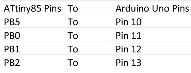
Figure 1: Wiring for ATtiny85 to Arduino Uno
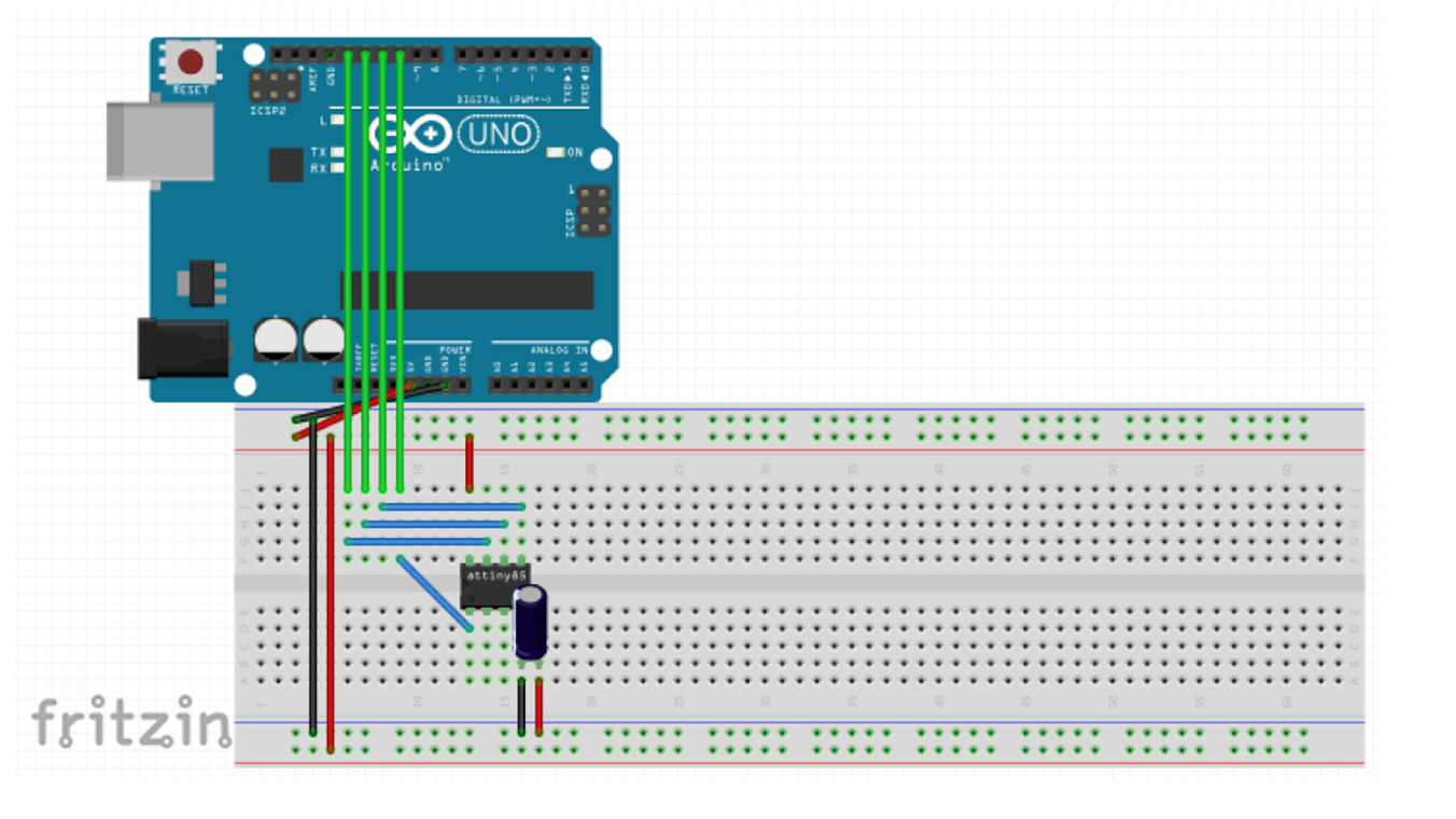
Figure 2: Wiring for ATtiny85 to Arduino Uno fritzing diagram
Programing ATtiny85
After wiring the ATtiny85 properly you should be able to program it. To do this, you first need to download the proper ATtiny85 libraries. Open Arduino IDE go to File then Preferences, a dialog box should pop up. Under “Additional Boards Manager URLs” paste this link https://raw.githubusercontent.com/damellis/attiny/ide-1.6.x-boards manager/package_damellis_attiny_index.json and then press ok to save. Then go to tools, then board and click on “Board Manager”. A pop up window should show up, scroll through the list and install the Attiny85 entry.
You could now program the ATtiny85. First go to tools and set the Programmer to “Arduino as ISP”. After run the example code “ArduinoISP” (under: files, examples, ArduinoISP). Upload the code to the Arduino Uno. After the upload finishes go to tools and change the board to ATtiny85. You can now successfully upload code to the ATtiny85.
ATtiny85 Code
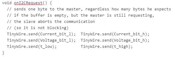
First we give the ATtiny85 an address. This address will enable the Arduino to see the ATtiny85 using I2C protocol. In setting up, enable the ADC by configuring both ADMUX and ADCSRA registers. We then use TinyWire.begin(“address”) to start I2C communication. Define TinyWire.onRequest(“function”) to create a function that sends data through I2C. During the loop we enable ADC and transfer the save byte values in the ADCL(low byte) and ADCH (high byte)r egister to another variable that we will send through I2C. We then wait for the ADC conversion to finish (until ADSC is 0). Once finished, the ADC readout pin from the ADMUX register can be changed to another PIN. The same code is use to obtain an analog read of voltage/current/temperature. The loop then ends and we create the function we mentioned in setup. We use “void function() {“”}” within this code we use TinyWire.send(“byte”) to send over a specific “byte” through I2C to the Arduino. See code below.

// ATtiny85 Address
#define I2C_SLAVE_ADDRESS 0x3
byte own_address = 0x30;  // 0x31, 0x32, 0x33 change addresses for each Attiny85

// Varibles being sent to Arduino
byte Current_bit_l;
byte Voltage_bit_l;
byte t_low;
byte Current_bit_h;
byte Voltage_bit_h;
byte t_high;

void setup() {
  ADMUX = 0b00000011;
  ADCSRA = 0b10000111;
  // config TinyWire library for I2C slave functionality
  TinyWire.begin( own_address );
  // register a handler function in case of a request from a master
  TinyWire.onRequest( onI2CRequest );
  // TinyWire.onRequest( onI2CRequest2 );
}

void loop() {
  // 11 clock cycles need to pass per adc
  // in order to change ADMUX
  // Current Reading
  ADMUX = 0b10000011;     //Reads pin PB3
  ADCSRA |= (1 << ADSC);  //Enable ADC
  Current_bit_l = ADCL;
  Current_bit_h = ADCH;

  while(ADCSRA & (1<
  // Voltage Reading
  ADMUX = 0b10000010;    //Reads pin PB4
  ADCSRA |= (1 << ADSC); //Enable ADC
  Voltage_bit_l=ADCL;
  Voltage_bit_h=ADCH;
  while(ADCSRA & (1<

  // Temperature reading
  ADMUX=0b10001111;      //Enable internal temp sensor
  ADCSRA |= (1 << ADSC); //Enable ADC
  t_low = ADCL;
  t_high = ADCH;

  while(ADCSRA & (1<)){} //wait until ADC Finishes delay(500); pinMode(1, OUTPUT); digitalWrite(1, HIGH); delay(500); digitalWrite(1, LOW); } // Request Event handler function //  --> Keep in mind, that this is executed in an interrupt service routine. It shouldn't take long to execute
}
Arduino Code
For the Arduino code, we include the wire library. Then in the Arduino loop we first use Wire.requestFrom(“ATtiny Address”,”number of bytes being received”) to request a certain number of bytes from the ATtiny85. We then use Wire.read(); to read the byte being sent over. Once we obtain the high and low bytes, we combine both bytes to form a 10 bit value. We then turn this 10 bit value to an actual voltage/current/temperature value. For voltage we use, voltage = (Vin*1024)/Vref. For current we use current = (Current_in*1024)/(10*shunt_resistor). For temperature we use Temperature_F = ((Temp_in-273.15)*1.8)+32. For power we use P=V*I. See code below.
![]()
//Attiny85 Slave Address
#define SLAVE_ADDR 0x30      //Attiny85 Address
#define SLAVE_ADDR_2 0x31    //Attiny85 Address
#define SLAVE_ADDR_3 0x32    //Attiny85 Address
#define SLAVE_ADDR_4 0x33    //Attiny85 Address

//Array 1
uint16_t Current_10;
uint16_t Voltage_10;
uint16_t Temp_10;

//Array 2
uint16_t Current_10_2;
uint16_t Voltage_10_2;
uint16_t Temp_10_2;

// repeat for additional modules

float ten_bit = 1023;
const int RS = 10;                // Shunt resistor value (in ohms)
const int VOLTAGE_REF = 1.1;      // Reference voltage for analog read
const float ratio = 0.0010752688; // each bit is (Vref/1023) V

// Array 1
float Current;       //current variable
float Voltage;       //voltage variable
float Power;         //power variable
float Temperature_F; //Temperature in Fahrenheit

// Array 2
float Current_2;       //current variable
float Voltage_2;       //voltage variable
float Power_2;         //power variable
float Temperature_F_2; //Temperature in Fahrenheit

// repeat for additional modules

void setup()
{
  Wire.begin();       // join i2c bus (address optional for master)
  Serial.begin(9600); // start serial for output
}

void loop()
{
  // Module 1
  Wire.requestFrom(SLAVE_ADDR,6);        // request 6 bytes from Attiny85 device address 4
  if (Wire.available())                  // slave may send less than requested
  {
    uint8_t temp_low = Wire.read();        // receive a byte as character
    uint8_t temp_high = Wire.read();       // receive a byte as character
    uint8_t voltage_low = Wire.read();     // receive a byte as character
    uint8_t voltage_high = Wire.read();    // receive a byte as character
    uint8_t current_low = Wire.read();     // receive a byte as character
    uint8_t current_high = Wire.read();    // receive a byte as character

    // combining bytes 10 bit
    Current_10 = ((current_high << 8) | current_low);
    Voltage_10 = ((voltage_high << 8) | voltage_low);
    Temp_10 = ((temp_high << 8) | temp_low);
    Temp_10 = Temp_10 - 20;

    // Current bit to Value
    Current = (Current_10 * VOLTAGE_REF)/ten_bit;
    Current = Current/(10 * RS);

    // Voltage bit to value
    Voltage = Voltage_10*ratio*45.83333333333;  //10.4792528736;

    // Power Calculation
    Power= Voltage*Current;

    // Temp bit to Fahrenheit
    Temperature_F = ((Temp_10-273.15)*1.8)+32; //temp is Fahrenheit

    Serial.println("Module 1");
    Serial.print("Voltage:    ");
    Serial.print(Voltage,5);
    Serial.println(" V");
    Serial.print("Current:    ");
    Serial.print(Current,5);
    Serial.println(" A");
    Serial.print("Power:      ");
    Serial.print(Power,5);
    Serial.println(" W");
    Serial.print("Temp:       ");
    Serial.print(Temperature_F,5);
    Serial.println(" F");
    Serial.println("");
    Serial.println("");
   delay(1000);
  }

  // Module 2
  Wire.requestFrom(SLAVE_ADDR_2,6);        // request 6 bytes from Attiny85 device address 4

  if (Wire.available())                    // slave may send less than requested
  {
    // use module 1 as a template
  }
  // repeat for modules 3 and 4

delay(1000);
}
Possible Future Update
Instead of using the ATtiny85 and the INA169, it may be more convenient to use the INA219. The INA219 can have a total of 16 addresses (by jumping certain connections (see INA219 for more details)) and can read the voltage/current/power, and send it via I2C to the Arduino. This will make the design cheaper and more efficient, as only one sensor would need to be powered instead of 2 sensors. Below is the working code for the INA219. The code is using 2 INA219 with 2 different addresses.
![]()
Adafruit_INA219 sensor219; // Declare and instance of INA219
Adafruit_INA219 sensor219_B(0x41);
void setup(void)
{
  Serial.begin(9600);
  sensor219.begin();
  sensor219_B.begin();
}
void loop(void)
{
  float busVoltage = 0;
  float current = 0; // Measure in milli amps
  float power = 0;

  busVoltage = sensor219.getBusVoltage_V();
  current = sensor219.getCurrent_mA();
  power = busVoltage * (current/1000); // Calculate the Power

  // ina219_B
  float busVoltage_B = 0;
  float current_B = 0; // Measure in milli amps
  float power_B = 0;

  busVoltage_B = sensor219_B.getBusVoltage_V();
  current_B = sensor219_B.getCurrent_mA();
  power_B = busVoltage * (current/1000); // Calculate the Power

  Serial.println("Ina219_A");
  Serial.print("Bus Voltage:   ");
  Serial.print(busVoltage);
  Serial.println(" V");

  Serial.print("Current:       ");
  Serial.print(current);
  Serial.println(" mA");

  Serial.print("Power:         ");
  Serial.print(power);
  Serial.println(" W");

  Serial.println("");
  Serial.println("");
  Serial.println("Ina219_B");
  Serial.print("Bus Voltage:   ");
  Serial.print(busVoltage_B);
  Serial.println(" V");

  Serial.print("Current:       ");
  Serial.print(current_B);
  Serial.println(" mA");

  Serial.print("Power:         ");
  Serial.print(power_B);
  Serial.println(" W");

  Serial.println("");

  delay(2000);
}
References/Resources
- How to Program Attiny85:
- How to set up INA169:
- INA169 data Sheet:
- ATtiny85 data sheet:
- INA219 data sheet: